BY02 (also known as BY70-2) is an Amateur cubesat by the China Aerospace Science and Technology Corporation and Beijing Bayi High School. It was launched on July 3 on a CZ-4B rocket from Taiyuan together with a Gaofen Earth observation satellite. BY02 is intended as a replacement for BY70-1, which was launched on 2016-12-28 and was placed on a short-lived orbit that decayed in a few months because of a launch problem.
Today, Wei Mingchuan BG2BHC announced on Twitter at 09:14 UTC that BY02’s beacon was on and would be left on at least until 12:50 UTC. I believe that this is the first time that the beacon has been on for an extended period of time, since during the early operations the beacon was only active on passes over China.
Since at 11:39 UTC there was a good pass over Spain, I went outside with my handheld Arrow 7 element yagi to do a recording. This post is an in-depth analysis of this recording and includes an explanation of the coding and telemetry format used by BY02.
The recording has been done with the Arrow 7 element yagi and a FUNcube Dongle Pro+ connected with a short coax. I aimed the antenna manually during the pass and held it in the horizontal polarization. I have published the recording in Zenodo, so it can be downloaded from there.
BY02 uses the frequency 436.200 MHz, the same as BY70-1, since it’s sharing its IARU coordination and ITU API as a replacement satellite. The coding and telemetry format is different to BY70-1, though, and closer to LilacSat-1 and Taurus-1, since BY02 also carries an FM to Codec2 transponder.
As LilacSat-1, BY02 uses 9k6 BPSK modulation, the CCSDS k=7 r=1/2 convolutional code, and 116 byte frames which are preceded by the CCSDS 32 bit syncword and scrambled with the CCSDS additive scrambler. The frame structure is also the same, with 35 bytes of Codec2 data and 81 bytes of telemetry interleaved in blocks.
The telemetry contents are different from LilacSat-1, though. For LilcacSat-1, the telemetry bytes formed a KISS stream that fragmented telemetry packets and marked their boundaries. For BY02, the 81 bytes form a complete CCSDS TM Space Datalink frame, albeit with a non-standard shorter 5 byte header that shrinks the 11 bit first header pointer field to 8 bits and doesn’t include the secondary header, synch, and packet order flags and the segment length ID. This 5 byte header is the same as used in the UHF downlink of the Longjiang-1/2 lunar orbiters.
Wei was kind enough to explain to me in detail the contents of these TM Space Datalink frames. There are two telemetry structures. One for the on-board STM32 microcontroller, and another for the on-board AVR microcontroller. There are three types of frames. The first one starts by 0x55 0x55 0x55 0x55 0x55 0x55 0x00 0x00 0x08 0x77 0x80 0x00 0x00 0x63 and then contains the first part of the STM32 structure. The second one starts by 0x55 0x55 0x55 0x55 0x55 0x55 0x00 0x26 and contains the second part of the STM32 structure, followed by the AVR structure, and then some 0xaa bytes for padding. The third type has only 0xaa bytes for padding. More details can be found in the gr-satellites telemetry definition for BY02.
I used Linrad to make the IQ recording, together with my Doppler correction GNU Radio flowgraph that uses gr-gpredict-doppler to perform real time Doppler correction with Gpredict (by the way I have updated the flowgraph to GNU Radio 3.8). The signal of interest was placed at 48kHz in the passband in order to avoid the DC spike. I have used a GNU Radio flowgraph by02_recording.grc to process the recording.
Since Linrad RAW files have a 41 byte header before the stream of int16_t IQ samples, it is a bit tricky to open them. Therefore, the flowgraph reads from stdin so that the stream can be passed in by running
tail -c +42 by02.raw > ./by02_recording.grc
The flowgraph filters the signal to a bandwidth of 10kHz and downconverts it to baseband. It computes average power in windows of 100ms and stores the information in a file for later processing. The analysis is done in this Jupyter notebook.
The figure below shows the signal power in this 10kHz bandwidth. The telemetry beacons can be seen as spikes that happen every 35 seconds. For reference, dotted green lines are drawn every 35 seconds in such a way that they line up with the telemetry transmissions, so that it’s easy to see which telemetry transmissions are missing. The elevation is also plotted in orange for reference.
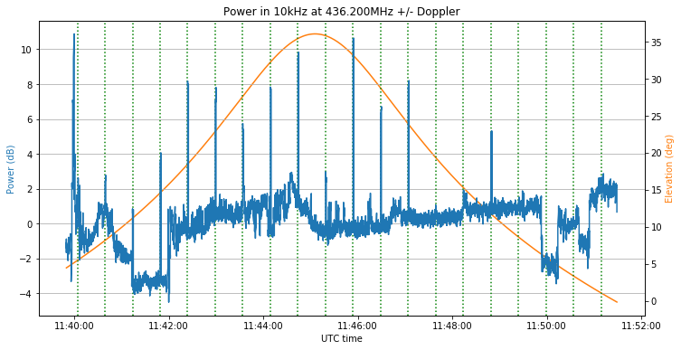
We can see that the noise floor varies a few dB depending on where I’m pointing the antenna. Some of the beacons are strong, but others are quite weak, even near the middle of the pass. This may be explained by a slow tumbling of the spacecraft.
If we plot all the beacons with respect to the dotted green lines, we see that the beacons measure approximately 1.6 seconds. A frame takes 200ms to transmit, so these beacons carry 8 frames.
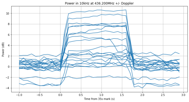
It turns out that a beacon consists of a padding frame, a frame carrying the first half of the STM32 data, a frame carrying the second half of the STM32 data, and 5 padding frames.
I have used gr-satellites to decode the frames and spent some time trying to tune the decoding parameters for this particular recording. It turns out that
--syncword_threshold 2 --clk_bw 0.1 --clk_limit 0.005 --fll_bw 10 --costas_bw 75
gives quite good results.
An important remark about --syncword_threshold is in order. The default syncword detection threshold allows up to 4 bit errors in the 32 bit syncword. Since there is no checksum or Reed-Solomon to throw invalid frames, this will produce false decodes and partially corrupted frames. This might be good when one wants to copy the Codec2 data in difficult conditions, but for decoding good telemetry frames, a lower threshold is recommended to prevent false decodes.
I have made some detailed plots of the beacons. The I and Q symbols after clock recovery and suppressed carrier recovery by a Costas loop are shown as blue and orange dots respectively. Since the signal is BPSK, a clean signal will have the I symbols clustered around +1 and -1 and only noise of small amplitude in the Q symbols.
The detections of the syncword by the decoder are shown as vertical lines. The colour of these lines corresponds to the type of the frame: green for padding frames, red for frames with the first half of the STM32 data, and purple for frames with the second half of the STM32 data and the AVR data. The master channel frame count (MCFC) of each Datalink frame is shown next to the syncword detection.
Beacons are numbered according to the dotted green lines in the plot above (starting by zero). The beacon number and an estimate of its SNR using the power measurement are shown in the title of the plot. The plots where at least one detection is made are shown below.
We can observe a few interesting things. Even though beacon 1 is very weak, there is a successful syncword detection. The frame is partially corrupted, though. For most beacons we miss the first padding frame, since the clock recovery and Costas loops are not able to lock fast enough. I don’t know if there is a preamble before this frame. Maybe this is reason why this frame is padding rather than useful data.
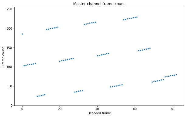
If you look at the master channel frame counts, you’ll see something interesting. It appears to jump between one beacon and the next. In fact, the figure below shows the value of the master channel frame count in each of the decoded frames (except for one frame in which this field was corrupted, which is not shown).
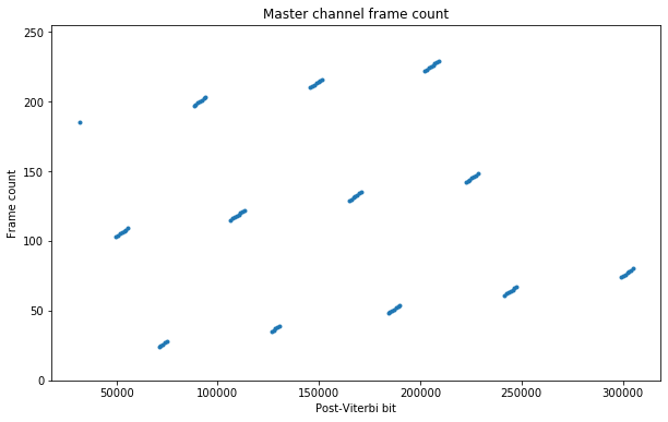
The jumps happen between each of the beacon transmissions. This is best seen in the figure below, which shows the post-Viterbi bit corresponding to each frame in the horizontal axis. We can see a gap corresponding to beacons 13 and 14, which we missed. More careful study shows that the master channel frame count jumps by adding 168 modulo 256.
All the frames are sent in virtual channel 0 and the virtual channel frame count always equals the master channel frame count plus one. Spacecraft ID 129 is used. The first header point field is always set to zero.
The data obtained from this recording can be found in the by02_data folder. This contains the decoded frames in KISS format, in hexdump, and the parsed values (note that telemetry conversion formulas are not implemented in gr-satellites, so the raw value of each field is printed).
From the parsed values we can see that the runtime field of the AVR data is in milliseconds and has reset 720 seconds before beacon 2 (so roughly at 11:29 UTC). The runtime field of the STM32 (which is split in two) is also in milliseconds and has reset 633 seconds before beacon 2 (so roughly at 11:30 UTC).
Always great explanations Dani! FB results.
What are the default settings for –clk_limit, –fll_bw 1 and –costas_bw in this decoder? Are defaults always the same for BPSK, unless otherwise adjusted?
Thanks,
Bob
Hi Bob, the defaults are –clk_bw 0.06 –clk_limit 0.02 –fll_bw 25 –costas_bw 50. You can see them by using –help. The defaults are the same for all the BPSK satellites.