Solar Orbiter is an ESA Sun observation satellite that was launched on February 10 from Cape Canaveral, USA. It will perform detailed measurements of the heliosphere from close distances reaching down to around 60 solar radii.
As usual, Amateur observers have been interested in tracking this mission since launch, but apparently ESA refused to publish state vectors to aid them locate the spacecraft. However, 18 hours after launch, Solar Orbiter was found by Amateurs, first visually, and then by radio. Since then, it has been actively tracked by several Amateur DSN stations, which are publishing reception reports on Twitter and other media.
On February 13, the spacecraft deployed its high gain antenna. Since it is not so far from Earth yet, even stations with relatively small dishes are able to receive the data modulation on the X band downlink signal. Spectrum plots showing the sidelobes of this signal have been published in Twitter by Paul Marsh M0EYT, Ferruccio IW1DTU, and others.
I have used an IQ recording made by Paul on 2020-02-13 16:43:25 UTC at 8427.070MHz to decode the data transmitted by Solar Orbiter. In this post, I show the details.
Just a look at the spectrum, which is shown in the figure below, reveals a lot about the modulation. There is a residual carrier and the data sidelobes extend up to the central carrier and null out there. This suggests that the modulation is PCM/PM/Bi-φ.
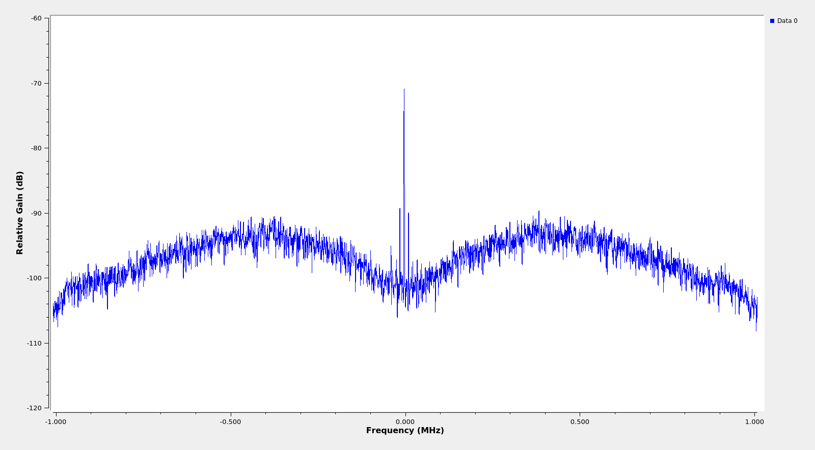
I often find a bit confusing the terminology used in DSN to describe the modulations. This article has a helpful explanation. In particular PCM/PM/Bi-φ means that the data is first Manchester encoded (Bi-φ or bi-phase is another term for Manchester) and then phase modulated onto an RF carrier. A phase modulation index much smaller than \(\pi\) is used to obtain a residual carrier. In the case of this Solar Orbiter recording, the modulation index is approximately \(\pi/2\).
The Manchester encoding produces data sidelobes that extend up to the residual carrier. Manchester encoding is equivalent to using a subcarrier frequency equal to the baudrate. If a subcarrier frequency greater than the baudrate was used (which is often described as PCM/PSK/PM), then the sidelobes wouldn’t extend up to the residual carrier and there would be a gap between the sidelobes and the residual carrier. Figure 3.1 in the article mentioned above gives a good visualization of the spectra of the different modulations. The PCM/PM/Bi-φ modulation is also called SP-L/PM.
The usual way of decoding a phase modulated signal with residual carrier is to lock a PLL to the residual carrier and then take the phase of the resulting signals. For small modulation indices it is also appropriate to take the imaginary part instead, which is an approximation that is much more efficient. We obtain a real signal that corresponds to the phase modulation.
Cyclostationary analysis shows that the baudrate is around 555.5kbaud. This is just a technical way of saying that we compute \(x_n \overline{x_{n-1}}\), where \(x_n\) is our signal and the bar denotes complex conjugation, and do Fourier analysis to the resulting signal, obtaining a tone at approximately 555.5kHz. In the case of a Manchester encoding signal or a signal with a subcarrier, it is probably better to perform this analysis on one of the sidelobes only, since each sidelobe alone looks as BPSK.
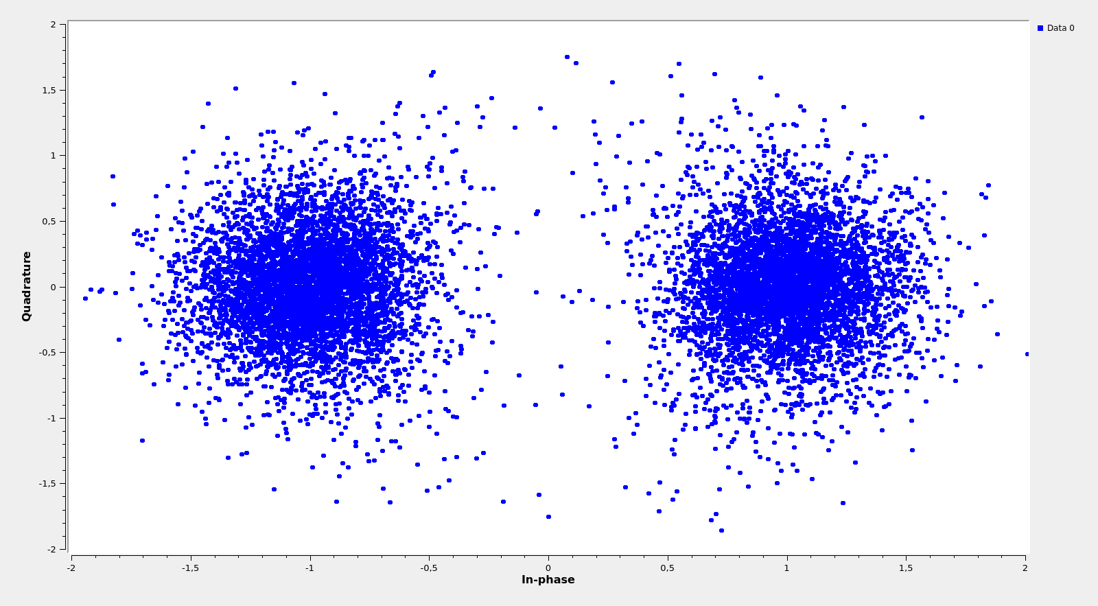
With this knowledge, we are ready to lock a constellation, as shown below, and obtain the bits of the signal. As we can see, the signal to noise ratio is quite high and there are few bit errors. The attentive reader will perhaps be wondering how I’ve managed to produce a BPSK constellation from a Manchester encoded real signal. This will be explained below.
There are many things that can be tried to make sense out of the bits, and it is easy to get lost if one doesn’t know what to look for and searches some kind of structure blindly. In fact, the bits seem to have too much structure that can send one chasing wild goose. For example, there is a strong self-correlation at 510 bits of lag that I don’t understand well where it comes from and probably doesn’t help to decode the signal.
Of course we expect some kind of CCSDS protocol, so it is helpful to try to correlate against the CCSDS syncwords defined in the TM Synchronization and Channel Coding blue book. This article can also save us some work, as it mentions Turbo codes at rates 1/2 and 1/4.
In fact, if we correlate the bits against the 0x034776C7272895B0 64-bit syncword marking the start of CCSDS r=1/2 Turbo codewords, we obtain a good match.
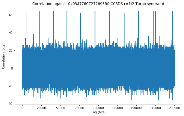
The separation between most of the detected syncwords is 17912 bits. This indicates that a block length of 8920 bits is used for the Turbo code, yielding 17848 bit codewords (see Table 6-2 in the blue book).
There are some other syncwords which are separated by 2257 bits (indicating 2193 bit frames). Two of these can be seen in the figure above. I don’t know what are these frames. The smallest CCSDS Turbo codeword has 3576 bits and, while this syncword can also be used for LDPC codewords, the sizes listed in Table 7-5 in the blue book don’t match this frame length.
Decoding the CCSDS Turbo codewords is easy, since (except for the block length), this is exactly the same FEC we used in the DSLWP mission. Therefore, there is a GNU Radio Turbo decoder in gr-dslwp.
Since gr-dslwp is only available for GNU Radio 3.7, I have made my decoder flowgraph in GNU Radio 3.7. This flowgraph needs only gr-dslwp to run. The first part of the decoder reads the IQ recording and uses an AGC which has been copied from the gr-satellites RMS AGC.
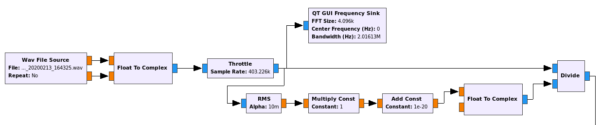
The second part of the decoder is shown below. We start by locking a PLL to the residual carrier and taking the complex argument to perform phase demodulation. What follows is perhaps an unorthodox way of demodulating a Manchester encoded real signal.
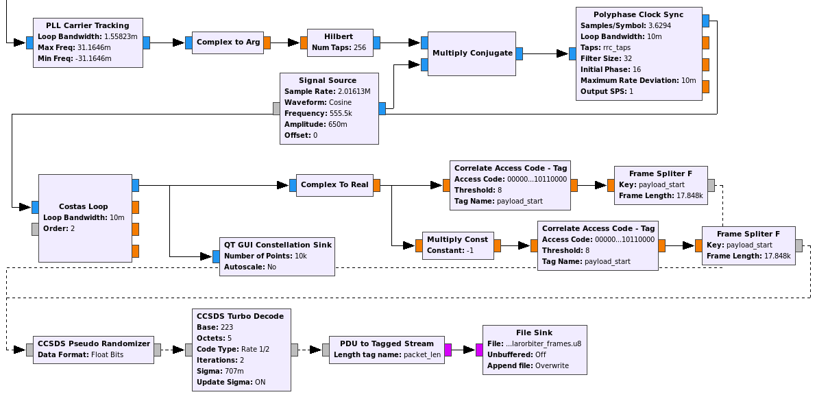
We take the Hilbert transform, obtaining a complex BPSK signal at a frequency equal to the baudrate. We move this BPSK down to baseband and then proceed normally, recovering the symbols and using a Costas loop to lock the constellation. This has the disadvantage that the symbols we obtain might have the wrong polarity. However, it is quick and easy to set up.
The other quick and easy method I know to demodulate a Manchester signal is to pretend it is BPSK at twice the baudrate, obtaining “half-symbols”. Then we detect the Manchester clock phase by looking at the transitions and accumulate pairs of adjacent “half-symbols”. This procedure has the disadvantage that the clock recovery is operating at less SNR, due to the higher baudrate.
After BPSK demodulation, we consider two branches to account for the possible polarity reversal, detect the syncwords and use the blocks from gr-dslwp to extract the codewords to PDUs, perform descrambling and Turbo decoding. The decoded frames are stored in a file.
Unfortunately, the Turbo decoder is not fast enough to run in real time in my laptop. It runs at approximately 25% of real time for the Solar Orbiter 555.5kbaud signal. I haven’t looked into optimising this.
The decoded frames are then analysed in this Jupyter notebook. They are TM Space Data Link frames, as described in this blue book. A total of 1665 frames were decoded from Paul’s 53.6 seconds recording. Out of these, 38 have invalid CRC. I suspect that the problem with these frames is caused by the 2193 bit “mysteriously short” frames (the Frame Splitter F block complains about these).
Spacecraft ID 650 is used for Solar Orbiter, and the recording contains 57 frames in virtual channel 0, 1567 frames in virtual channel 2, and 3 frames in virtual channel 4. According to the master channel frame count, only 32 frames were lost. I haven’t attempted to analyse the data any further by trying to look at upper level protocol layers.
The material used in this post, including the GNU Radio flowgraph, can be found here. The IQ recording made by Paul can be downloaded here.
Great work!
Since the decoding is done against BPSK, do we use USB demod on only one of the side lobes?
Or, is FM used on the entire signal?
Thanks!
Hi Scott,
Decoding is done against BPSK, but (perhaps counter-intuitively) both sidelobes are used. In more detail, once you do phase demodulation, the signal is real, so technically there is only one sidelobe. Depending on who you ask, the spectrum of the real signal should only be considered for positive frequencies, or it is symmetric about 0 Hz. This means that there aren’t two sidelobes any longer. In some sense, both sidelobes have merged in one.
It is recommended to use at least 2MHz bandwidth to record the signal, in order to process both sidelobes (either as I have done or in another manner). If for some reason someone uses less bandwidth to record just one of the sidelobes, then it is possible to process it as a BPSK signal, but 3dB SNR are lost and (more importantly), the ability to do phase tracking using the rather powerful residual carrier is lost. A better idea is if recording with a limited bandwidth is important is to record both the residual carrier and one sidelobe. Then phase tracking can be done on the residual carrier and then demodulation can be made, even though one sidelobe is missing. Still 3dB SNR are lost, of course.
Regarding your second question, the whole signal is phase modulated.
Excellent work and explanation. I tried another tool and came to the BPSK and 555 kb. But unfortunaltely this tool was developed for HF/VHF and UHF so it is not very strong with high data rates.
73 de Roland
Fantastic work!
From Bertrand Pinel F 5PL ,
Filled with Wonder about this work . Bravissimo !
If interested , ready to supply some other I/Q files from
Solar Orbiter .
73
nice work!
apropos upper level protocol layers; doing: bytes(frames[crc_ok,3]).decode(‘ANSI’,’STRICT’)” saw some interesting similar headers like RIFF container raster bitmap
(“!”#$%&'()*+,-./0123456789:;?@ABCDEFGHIJKLMNOPQRSTUVWXYZ[\]^_`abcdefghijklmnopqrstuvwxyz{|}”…)
Hi!
I’m sorry but I completely disagree with your finding. By doing
frames[crc_ok,3]you are taking the fourth byte of each of the packets with correct CRC. Since these are CCSDS TM Data Frames, the fourth byte is the virtual channel frame count, which is 8 bits long. Thus, disregarding changes between different virtual channels (which are or less uncommon),frames[crc_ok,3]is just an 8 bit counter. When converted to ASCII you get (no surprises) a looping ASCII table.my mistake, i forgot about the first 6 bytes of TMPrimaryHeader
best regards
Hi Daniel,
Link toward Paul Marsh M0EYT IQ recording are no more valid.
Is there by any chance a possibility to get a link that would be working ?
73 de Bernard, f6bvp
Hi Bernard,
I’ve just uploaded the file here.
Daniel,
Thanks for the wav file.
Very kind of you. I do appreciate.
Bernard
Hello Daniel,
The link to the IQ recordings are no longer valid.
Could you please upload them again?
Thank you so much and sorry for the inconvenience.
Hector
Hi Hector,
The recording is now hosted at http://eala.destevez.net/~daniel/grcon2020-workshop/
I’ll update the link in the post.
Thank you for the quick response Daniel, it’s much appreciated! 🙂
Hi Daniel, congratulations very well explained. Any experience demodulating the NOAA 15 CDA @ 2247.5 MHz? any recommendation ?
TIA
Hi Vicente, I haven’t worked before with the NOAA 15 CDA signal.
Thank for the quick reply, I will continue trying to decode. Best regard
Hello again, I made a big mistake, when I said NOAA CDA signal, I was referring to NOAA HRPT Signal. Based in your work (thank again) I made the demodulator work and obtain raw symbols. I still working in the deframer to finally obtain a raw16 file. I know that gr-hrpt exists, but I want to made from scratch. I am currently fighting to pack and save in a file a 10 bits word in 16 bits format. please advise. TIA