A while ago I spoke about feeding an external reference to the LimeSDR USB. Now I wanted to use an external reference with the LimeSDR Mini that I have in my QO-100 groundstation to lock all the system to GPS. Preferably I wanted to use 27MHz as the reference, since this is what I am using in my LNB, so this would save me from having to run 10MHz or another frequency to the groundstation.
I wasn’t so sure how well this would work, since there are a few threads with questions in the MiriadRF forums, but I haven’t seen any explaining things in a clear way. There are different anecdotes of things that worked or didn’t work for several people, but not that many definitive answers. Among all the threads, this one seems mostly helpful.
Somewhat surprisingly, everything has worked well on the first try. I am now using a 27MHz external reference with my LimeSDR Mini. Hopefully this post will be of help to other people.
The relevant part of the LimeSDR Mini v1.2 schematic is shown in the figure below (click on it to view it in full size).
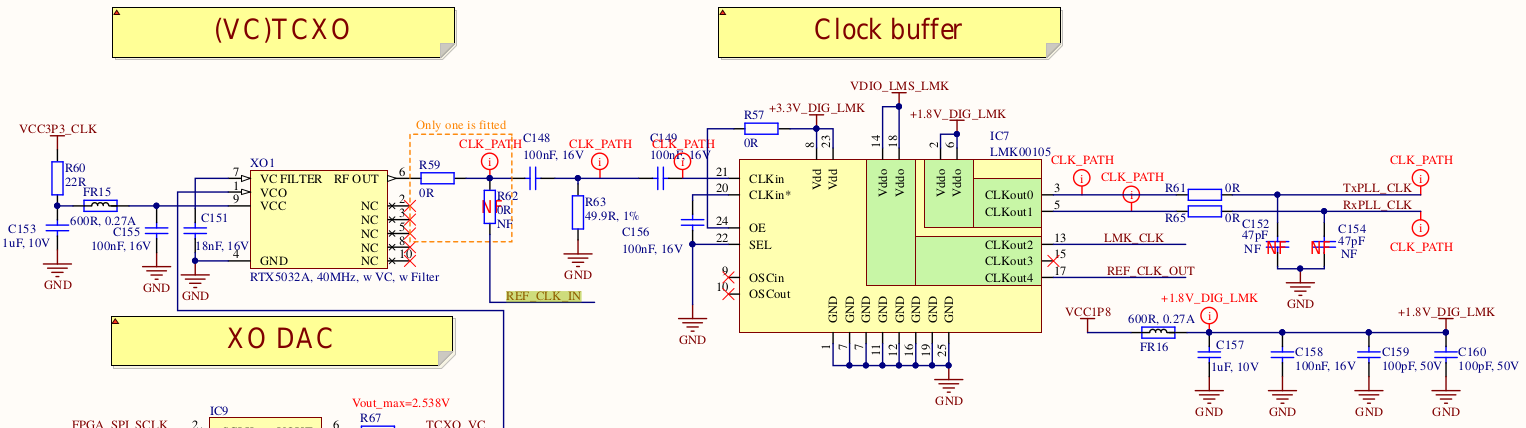
As we see, there is a 40MHz VCTCXO that feeds an LMK00105 clock buffer. This fans out the clock to different parts of the LimeSDR Mini, including the LMS7002M RFIC (TxPLL_CLK and RxPLL_CLK), the FPGA (LMK_CLK), and the clock output U.FL connector (REF_CLK_OUT).
It is possible to feed in an external clock instead of using the VCTCXO by removing the 0 Ohm resistor R59 and installing R62, which is not fitted by default. The 0 Ohm resistor R62 goes directly to the clock input U.FL connector.
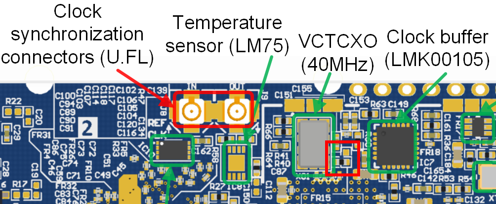
The figure below shows the LimeSDR Mini board. R59 and R62 are located in the smaller red box. There are only three pads for the two resistors, so they share a common pad and it is only possible to install one of them. To switch R59 to R62, it is enough to rotate the resistor in the red box by 90º (so in the figure the resistor would be rotated from a horizontal position to a vertical position).
This is the only hardware modification that needs to be done. There is also the question of the electrical specifications of the external reference signal. The LMS7002M datasheet says that the chip accepts a PLL reference between 10MHz and 52MHz.
Additionally, we need to take care about what the LMK00105 accepts. Its datasheet says that for a single-ended clock supplied through the CLKin pin, the peak-to-peak voltage swing should be between 0.3V and 2V. Since the clock input connector of the LimeSDR Mini is terminated to 50 Ohms, the clock input should be between -6 and 10dBm.
In my case, I am using a DF9NP PLL to generate the 27MHz reference. This gives a sine output with an open circuit voltage of 3.1V, which would give around 7.8dBm (or maybe a bit less) to a 50 Ohm load. Between the PLL and the LimeSDR Mini I have several metres of 75 Ohm coax and a 3dB splitter, so the clock input to the the LimeSDR mini is probably around 3dBm, perfectly within margins.
Finally, there is the matter of software. The LimeSuite driver needs to know about the reference frequency that you are feeding to the LimeSDR Mini. This is done by calling the LMS_SetClkFreq() function in the LimeSuite API. Probably it is best to do this right after initializing the chip, before setting up the sample rate or LO frequencies. As an example, you can see here how I am doing it in my limesdr_linrad software (which was described in this post).
These are all the steps needed to use an external reference with the LimeSDR Mini. Apparently it is possible to use any external clock between 10 and 52MHz just by changing a resistor and calling an API function. In particular, it is not necessary to modify the FPGA gateware. I understand that there is a NIOS CPU in the FPGA gateware that runs from the reference clock. This means that this CPU will run slower or faster depending on which reference frequency you use, but I don’t think it is a major concern.
Thank you Daniel for your interesting article. I have two questions for you.
1) How do you run a command on LimeSuite ? Can you tell me in wich menu in LimeSuite GUI ? I saw the ‘API Calls’ in Modules menu, but no LMS_SetClkFreq instruction there.
2) Do you know if the frequency may be set by SDR Console software ? (Left panel / More and Clocks tab).
thank you Daniel more generally for your ever interesting publications
Christian, F5UII
https://www.f5uii.net
Hi Christian,
The call to LMS_SetClkFreq() should be done when using the LimeSuite API. Under LimeSuite GUI I believe that the appropriate way to set the external reference frequency is to set the “Reference clock” in the SXR or SXT tabs.
I don’t know about SDR Consoled, but I think that SDRAngel has an option to set the external clock frequency.
How is the precision of the oscillator about frequency more than 2700Mhz?
Sorry, I don’t understand your question.
Hello Daniel,
Is it possible to use an external clock on LimeSDR mini with only one input and no output ?
To generate a clock, can I just create a square wave with a signal generator and giving it to the Lime, or I am missing something ?
Thank you
Hi Theo, I’m not sure I understand your question about “one input and no output”.
You can generate an external clock with a signal generator, provided it has the electrical characteristics that the LMK00150 and the rest of the system needs, and that you change the resistor as described. If the clock you use is not 40MHz, you will also need to modify your software to call LMS_SetClkFreq(). Otherwise all the calculations for the LMS7200M PLLs will be wrong.
Thank you for your answer. I’ll be clearer.
LimeSDR mini has 2 U.FL connectors for the clock synchronization. Should both be linked to my signal generator ? Or only using the IN connector is enough ?
theo
Only the IN connector needs to be connected to the signal generator. As you can see in the schematic, the OUT connector is an output from the LMK00150 clock buffer.