In my previous posts I have been decoding LTE PDSCH (physical downlink shared channel) transmissions from an IQ recording of an eNB and looking at the MAC PDUs with Wireshark. The analysis I have done of the upper layer protocols is somewhat limited because I have decoded only 500 ms of traffic and because I don’t have the encryption keys, and also because I’m just beginning to learn how the LTE upper layers work. When doing this analysis I thought that it would be good to have a more complete example that I could use as a reference. A Google search for examples of PCAP files containing LTE MAC PDUs yields very little, so I thought I would make my own example with srsRAN. In this post I show how to set up an srsRAN LTE eNB and UE communicating over ZMQ on a single machine and then analyze the traffic in Wireshark.
Running srsRAN
The setup I’m doing is essentially the same as described in the srsRAN 4G with ZMQ Virtual Radios application note. This involves running srsepc, srsenb and srsue in a single machine. The srsepc application is the EPC (evolved packet core), which is, so to speak, the core or “backend” of the network. It controls authentication, serves as IP gateway, and performs other functions such as mobility management. The srsenb and srsue applications are the eNB (base station) and UE (user equipment) respectively. In this setup they will exchange IQ data over ZMQ sockets, but in real life they would communicate over RF. The srsenb and srsepc applications communicate over IP, using the loopback interface in this case.
I’m using the srslte-avx2 Arch linux package. Currently, it is version 23.11, which is the latest, although for some reason the applications report version 23.4.0 when run with the --version argument. The instructions in this post can also be followed if srsRAN_4G is installed in another way, such as building from source as indicated in the ZMQ application note.
I have made my own configurations starting from the examples (these are installed in /usr/share/srsran in Arch). Here I will detail the configuration changes I’ve made.
In enb.conf and ue.conf I’m enabling the ZMQ sockets. These saves me from having to pass these as arguments when running srsenb and srsue, which is what the application note does. Additionally, in ue.conf I set the netns = ue1 parameter, which also saves me from having to indicate this as a command line argument.
I’m enabling all the dumps to PCAP that are supported by srsRAN. In enb.conf I’m recording LTE MAC frames to a PCAP and S1AP frames to another PCAP (and also NR MAC frames to another PCAP, but NR is not used in this setup). S1AP is the protocol that the eNB and the EPC use to communicate. In epc.conf I’m also enabling the PCAP capture. In ue.conf I’m enabling PCAP dumps for the MAC and the NAS (non-access stratum, which is a control channel between the UE and the EPC).
Regarding encryption, when doing this test for the first time it’s probably better to leave it disabled, which is the default. After understanding how everything works, I’ve enabled encryption in the following way. In epc.conf I set
encryption_algo = EEA2This means that the NAS layer will use EEA2 encryption. EEA2 is EPS encryption algorithm 2, which is AES-128.
In enb.conf I set
eea_pref_list = EEA2
This will force the use of EEA2 encryption in communications with the UE. Here it is important to use EEA2 instead of EEA1 because Wireshark cannot decrypt EEA1.
In ue.conf I set pdcp_level = debug in the [log] section. This will make the UE log its encryption and integrity keys. Then we can copy these into Wireshark to perform decryption and integrity checking. These keys are derived from the USIM key, which we have in ue.conf and user_db.csv, so I guess we could calculate the keys instead of logging them, but I haven’t looked into how the key derivation algorithms work.
I have also enabled the GUIs in enb.conf and ue.conf, although this isn’t really necessary.
Before running the applications, we need to create the network namespace for the UE. This is done with
sudo ip netns add ue1
Then we can start each of the srsRAN applications. Some of them need to be run with sudo (I guess this is necessary because they set up Linux network interfaces). I start each of them in a different terminal in the order indicated here, and wait a couple seconds between starting each so that they can start up completely.
sudo srsepc epc.conf
srsenb enb.conf
sudo srsue ue.conf
With this configuration the EPC has IP address 172.16.0.1 and the UE has IP address 172.16.0.2. I use the following command to generate some ping packets: ping 172.16.0.2 generates downlink traffic, and ip netns exec ue1 ping 172.16.0.1 generates uplink traffic.
sudo bash -c "ping -n 10 172.16.0.2
    && ip netns exec ue1 ping -n 10 172.16.0.1
    && sleep 120
    && ping -n 10 172.16.0.2
    && sleep 120
    && ip netns exec ue1 ping -n 10 172.16.0.1
    && ping -c 10 -s 1450 172.16.0.2"
This command first sends 10 downlink pings and then 10 uplink pings. Then it waits for 2 minutes. During this time the UE will enter the idle state and disconnect from the RRC. Then there are 10 downlink pings. The network will page the UE to wake it up, the UE will reconnect and receive the pings. Then there are another 2 minutes of wait, during which the UE goes back to idle. After this, the UE tries to send uplink pings. To do this, it reconnects to the network, but there is no paging, since it is the UE the one which wants to send data. Finally, there are some large ping packets sent in the downlink direction. All of these pings have their corresponding replies going in the opposite direction, so the data traffic is really bidirectional.
The messages written to the standard output and standard error by each of the tools can be seen in this folder.
Analysis in Wireshark
It is necessary to do some configuration to parse the PCAPs generated by srsRAN, which use custom DLTs, for instance to put UDP packets directly in a PCAP without using IP packets. The configuration is described in the Examining PCAPs with Wireshark section of the srsRAN documentation. Additionally, some familiarity with how to configure the LTE dissectors is helpful (see the post about the PDSCH).
eNB MAC layer
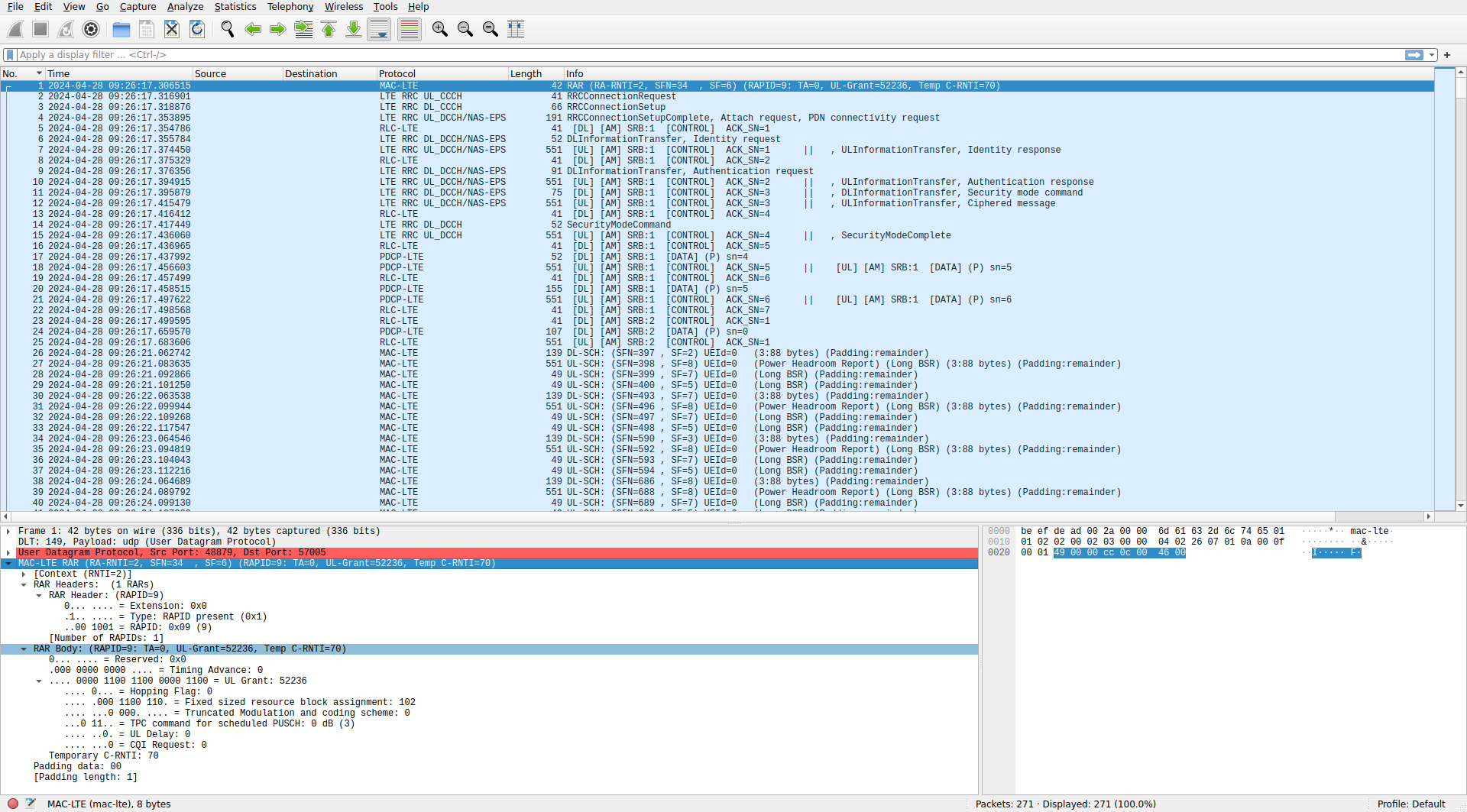
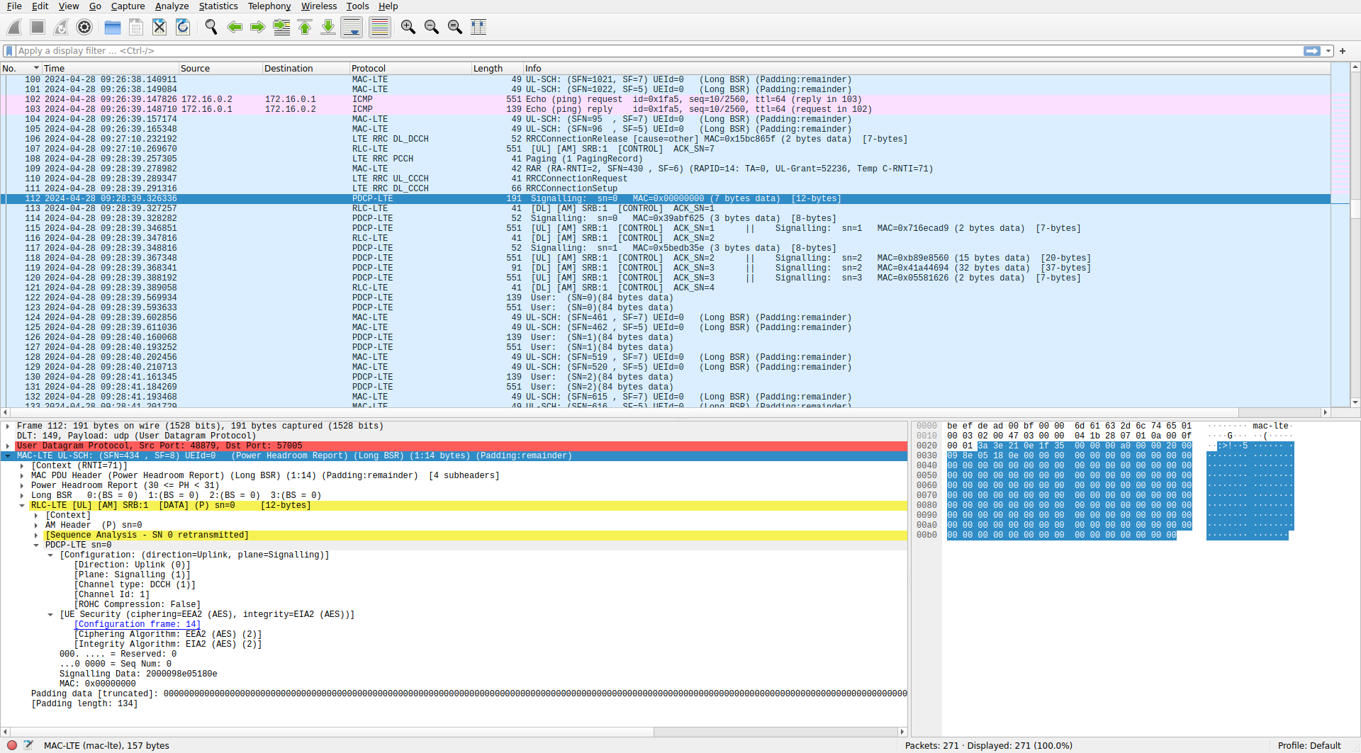
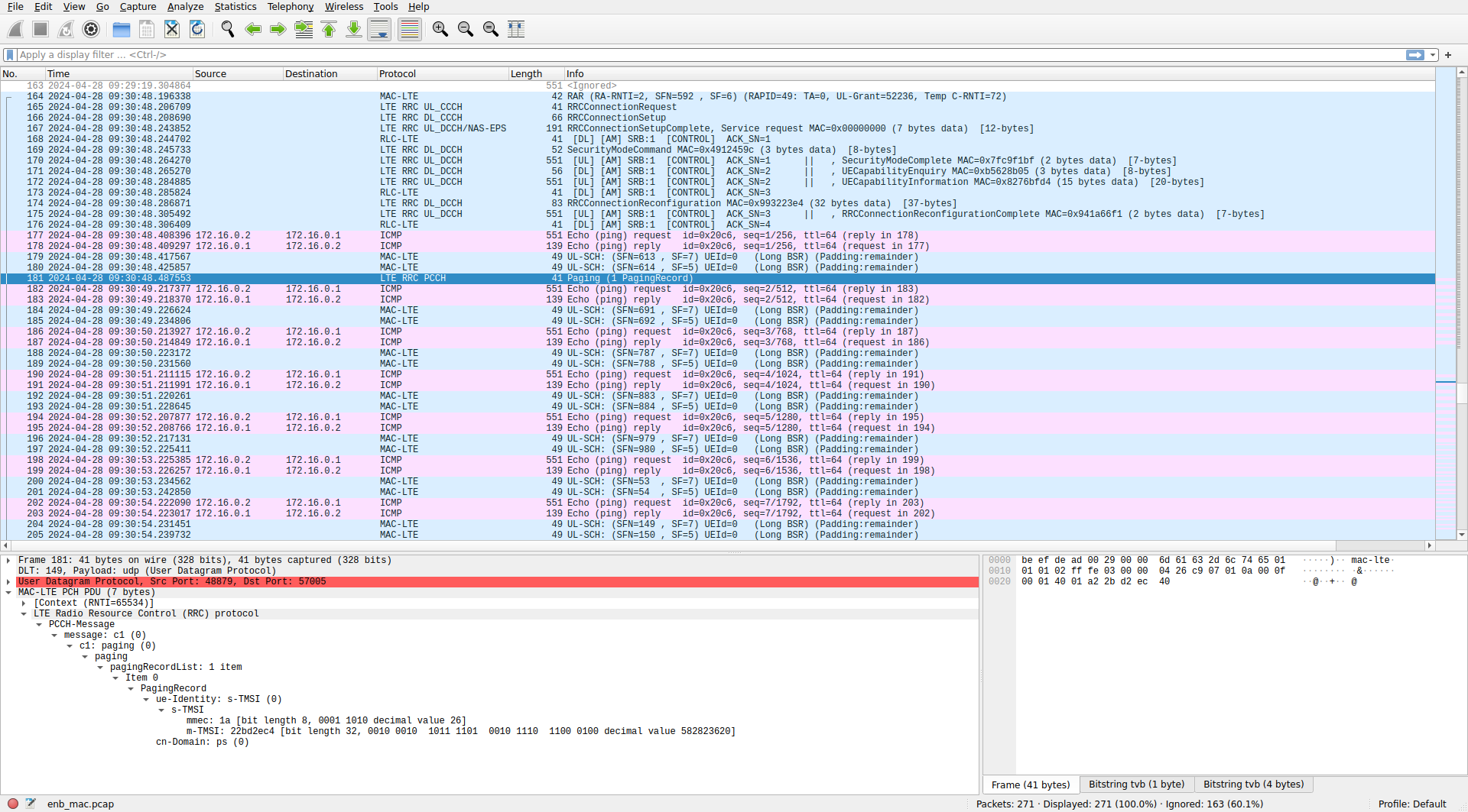
We start by looking at enb_mac.pcap, which contains the MAC layer data as seen by the eNB. Our first view into the eNB MAC layer looks like this (click on the image to view it in full size).
Network connection
The first MAC PDU we see is a RAR (random access response), which is generated as a reply to the UE PRACH transmission. After detecting the cell and decoding the MIB, SIB1 and SIB2, the UE transmits in the PRACH to begin connecting to the eNB. The PRACH transmission appears in the stdout of srsue:
Random Access Transmission: seq=9, tti=341, ra-rnti=0x2
It also appears in the stdout of srsenb:
RACH: tti=341, cc=0, pci=1, preamble=9, offset=0, temp_crnti=0x46
The RAR that we see in the PCAP is the response to this PRACH transmission. We see that its RA-RNTI matches the one used in the PRACH transmission. The RAPID (random access preamble ID) matches the seq parameter indicated by srsue.
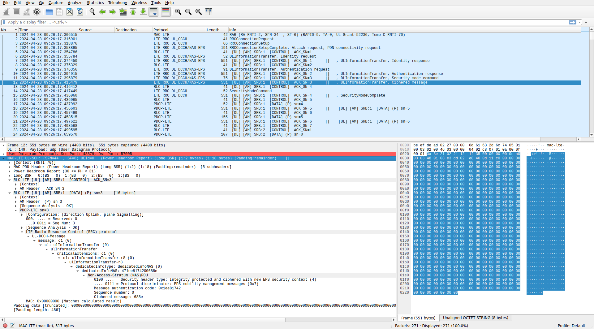
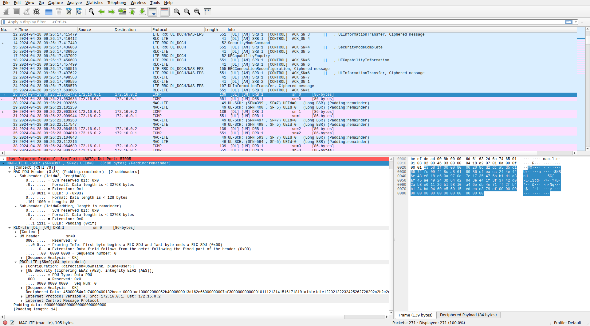
After the RAR we see some control traffic going in both directions. At first, this data is unencrypted and can be dissected by Wireshark. In packet 11 there is a “Security mode command” sent in the NAS from the EPC to the UE. After this point, NAS communications become encrypted, and we can see that the NAS message sent in the uplink direction in packet 12 gets displayed as “Ciphered message”.
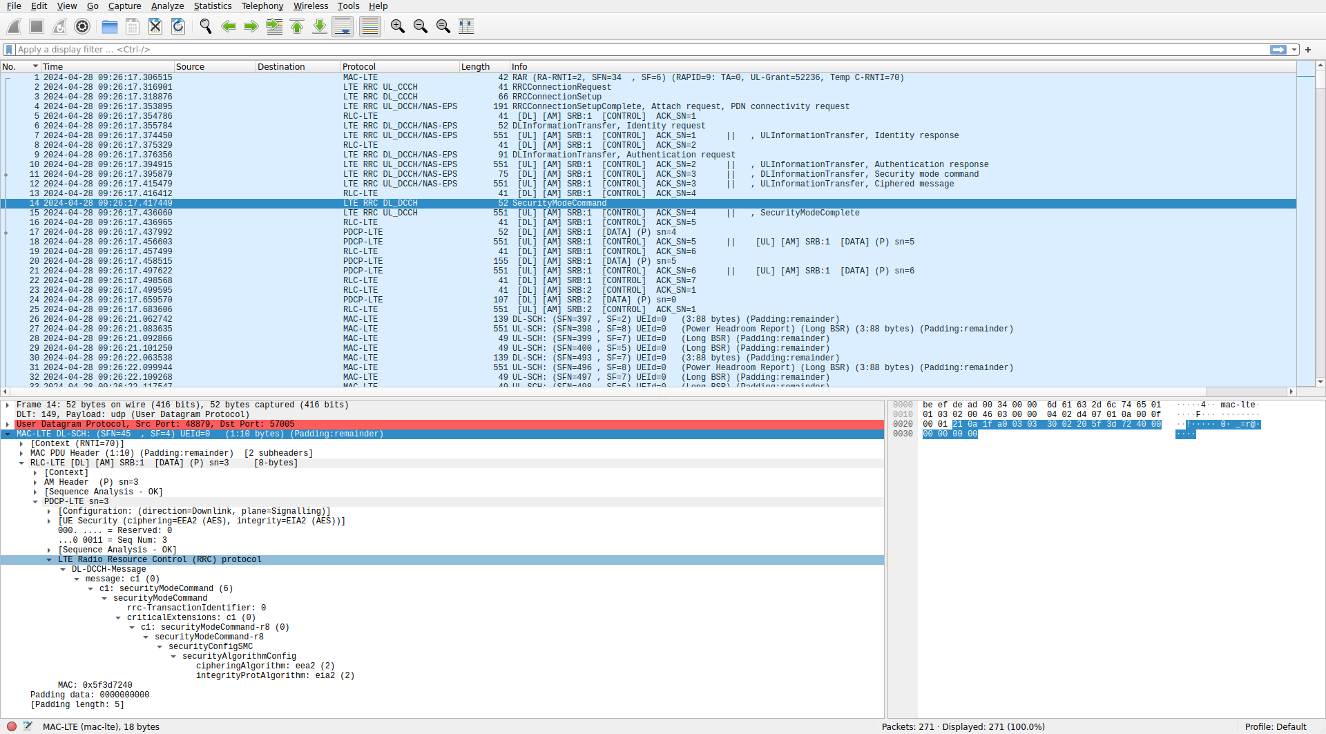
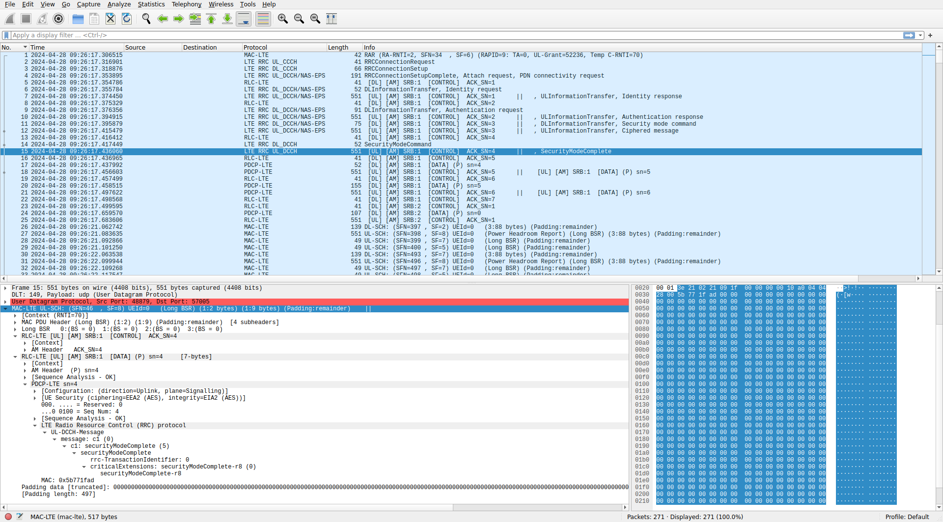
In packets 14 and 15 there are SecurityModeCommand and SecurityModeComplete RRC messages. These stablish encryption and integrity for communications between the UE and eNB. After this point, PDCP packets in SRBs 1 and 2 are displayed as “[DATA]” instead of being dissected as RRC messages, because their payload is encrypted.
The ping packets begin in packet 26. These are only displayed as MAC PDUs with LCID 3, because the MAC-LTE dissector parameter “Source of LCID -> drb channel settings” is set to “Configuration protocol”. The control messages that set up the DRB that uses LCID 3 are encrypted, so Wireshark cannot dissect these messages any further until we decrypt this information (or until we guess what RLC protocol is used in this DRB and tell Wireshark by means of a static table).
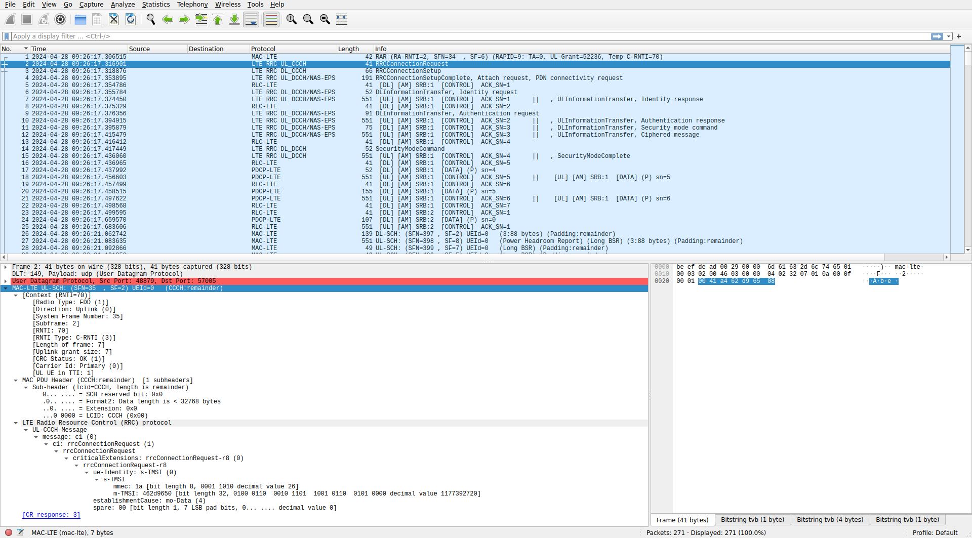
Let us now look at the control traffic step by step. After receiving the RAR, the UE sends an RRC connection request. This is an UL-CCCH message which contains the TMSI. The TMSI is a temporary and pseudorandom ID for the UE which is used almost everywhere in lieu of the IMSI (the unique ID for the UE stored on the SIM) to prevent tracking of UEs by eavesdroppers. No radio bearers are established at this point, so the message is sent in LCID 0, which is the CCCH (common control channel), a channel used by UEs which do not have an RRC connection with the network yet. The UE uses the temporary C-RNTI assigned to it in the RAR to transmit this PDU.
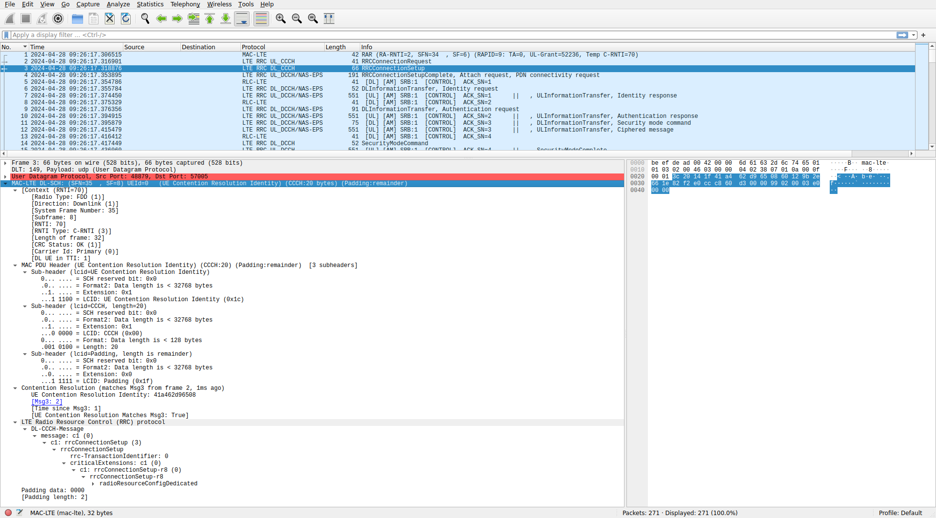
The network replies with an RRC connection setup message. The MAC PDU contains a UE Contention Resolution Identity control element. This is used to disambiguate between several UEs that could potentially have transmitted in the PRACH with the same RAPID and RA-RNTI simultaneously. The contention resolution contains the data 41a462d96508, which is the ASN.1 encoded RRC connection request that the UE sent. Since this contains the TMSI, it serves to disambiguate between two UEs transmitting in the PRACH at the same time, as it is extremely unlikely that both would have chosen the same RAPID, RA-RNTI and TMSI. After the contention resolution, there is a DL-CCCH message transmitted in the CCCH. This contains the RRC connection setup message. Its contents are rather long, so they are expanded below in text form.
The RRC connection setup configures SRB 1. It is implicit that this uses the RLC AM protocol and LCID 1, because this is the typical configuration (it is so typical that Wireshark already knows this via the “Attempt to dissect LCID 1&2 as SRB 1&2” MAC-LTE option). It also contains many other configuration parameters for the UE, including the configuration of the BSR (buffer status report) and PHR (power headroom) of the uplink MAC, which we will see in action in the next uplink PDUs. Another configuration parameter is pA, which I mentioned when talking about downlink power allocation. In this srsRAN setup the UE and eNB are single-port, so antennaInfo sets Transmission Mode 1, which is single-port transmission over port 0.
radioResourceConfigDedicated
    srb-ToAddModList: 1 item
        Item 0
            SRB-ToAddMod
                srb-Identity: 1
                rlc-Config: defaultValue (1)
                    defaultValue: NULL
                logicalChannelConfig: defaultValue (1)
                    defaultValue: NULL
    mac-MainConfig: explicitValue (0)
        explicitValue
            ul-SCH-Config
                maxHARQ-Tx: n4 (3)
                periodicBSR-Timer: sf20 (3)
                retxBSR-Timer: sf320 (0)
                ..0. .... ttiBundling: False
            timeAlignmentTimerDedicated: infinity (7)
            phr-Config: setup (1)
                setup
                    periodicPHR-Timer: sf50 (2)
                    prohibitPHR-Timer: sf0 (0)
                    dl-PathlossChange: dB3 (1)
    physicalConfigDedicated
        pdsch-ConfigDedicated
            p-a: dB0 (4)
        pucch-ConfigDedicated
            ackNackRepetition: release (0)
                release: NULL
        pusch-ConfigDedicated
            betaOffset-ACK-Index: 6
            betaOffset-RI-Index: 6
            betaOffset-CQI-Index: 6
        uplinkPowerControlDedicated
            p0-UE-PUSCH: 0 dB
            deltaMCS-Enabled: en0 (0)
            .1.. .... accumulationEnabled: True
            p0-UE-PUCCH: 0 dB
            pSRS-Offset: 3
        cqi-ReportConfig
            nomPDSCH-RS-EPRE-Offset: 0dB (0)
            cqi-ReportPeriodic: setup (1)
                setup
                    cqi-PUCCH-ResourceIndex: 0
                    cqi-pmi-ConfigIndex: 38
                    cqi-FormatIndicatorPeriodic: widebandCQI (0)
                        widebandCQI: NULL
                    .... ...1 simultaneousAckNackAndCQI: True
        antennaInfo: explicitValue (0)
            explicitValue
                transmissionMode: tm1 (0)
                ue-TransmitAntennaSelection: release (0)
                    release: NULL
        schedulingRequestConfig: setup (1)
            setup
                sr-PUCCH-ResourceIndex: 0
                sr-ConfigIndex: 15
                    [Periodicity: 20]
                    [Subframe Offset: 0]
                dsr-TransMax: n64 (4)
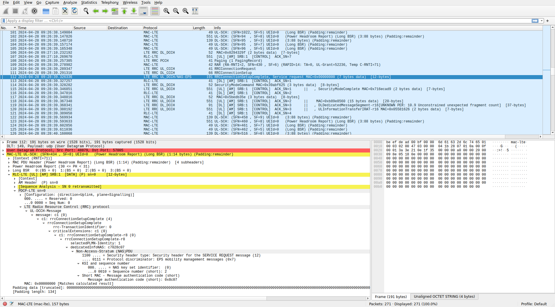
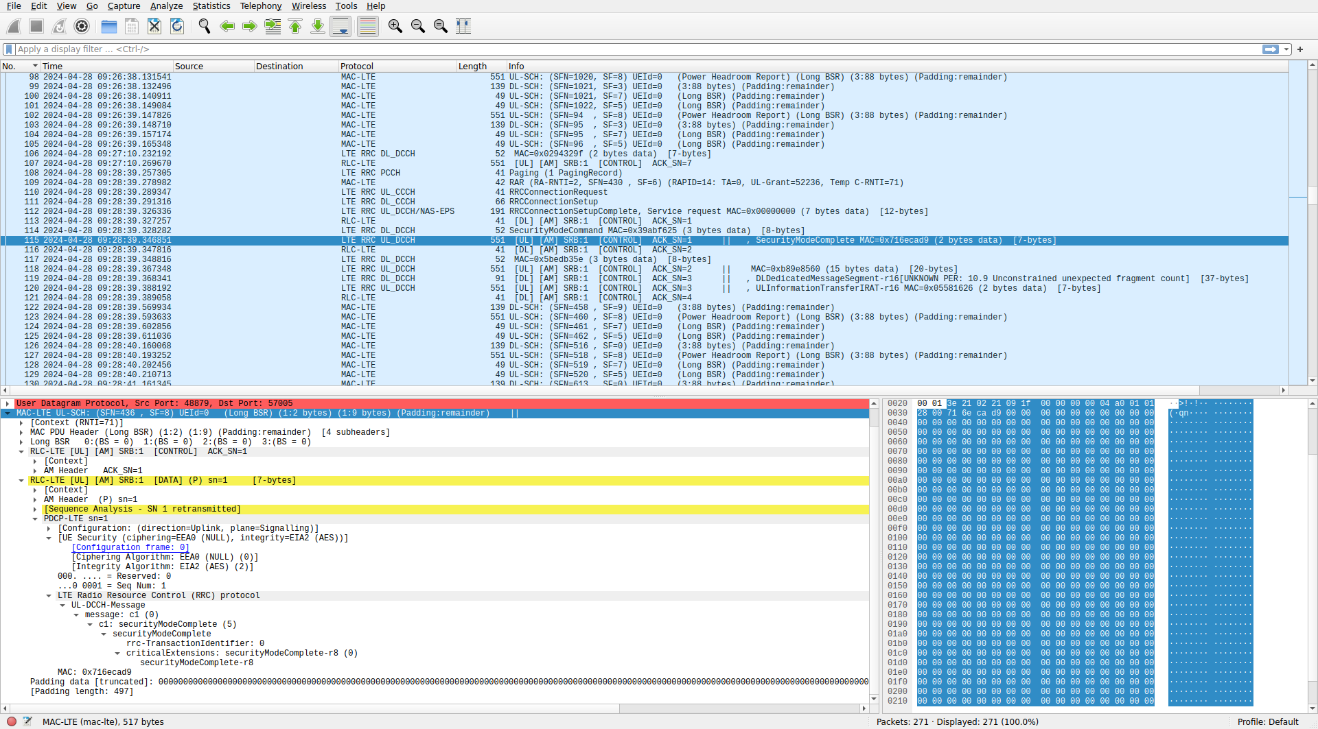
The UE then sends an RRC connection setup complete message. This MAC PDU also contains control elements with a power headroom report and a BSR, which indicates how much the transmit buffers of the UE are filled. The eNB uses this information as feedback for uplink transmit power control and for uplink scheduling. I will not be looking at these in detail in this post, but we will see that many uplink MAC PDUs contain these control elements. After the power headroom report and BSR, there is an SDU in LCID 1. Wireshark knows that this LCID corresponds to SRB 1, which uses the RLC AM protocol, so it dissects the SDU using that protocol (below it will be shown in more detail). After the SDU, there is a lot of padding, because the size of the uplink grant transport block was much larger than needed.
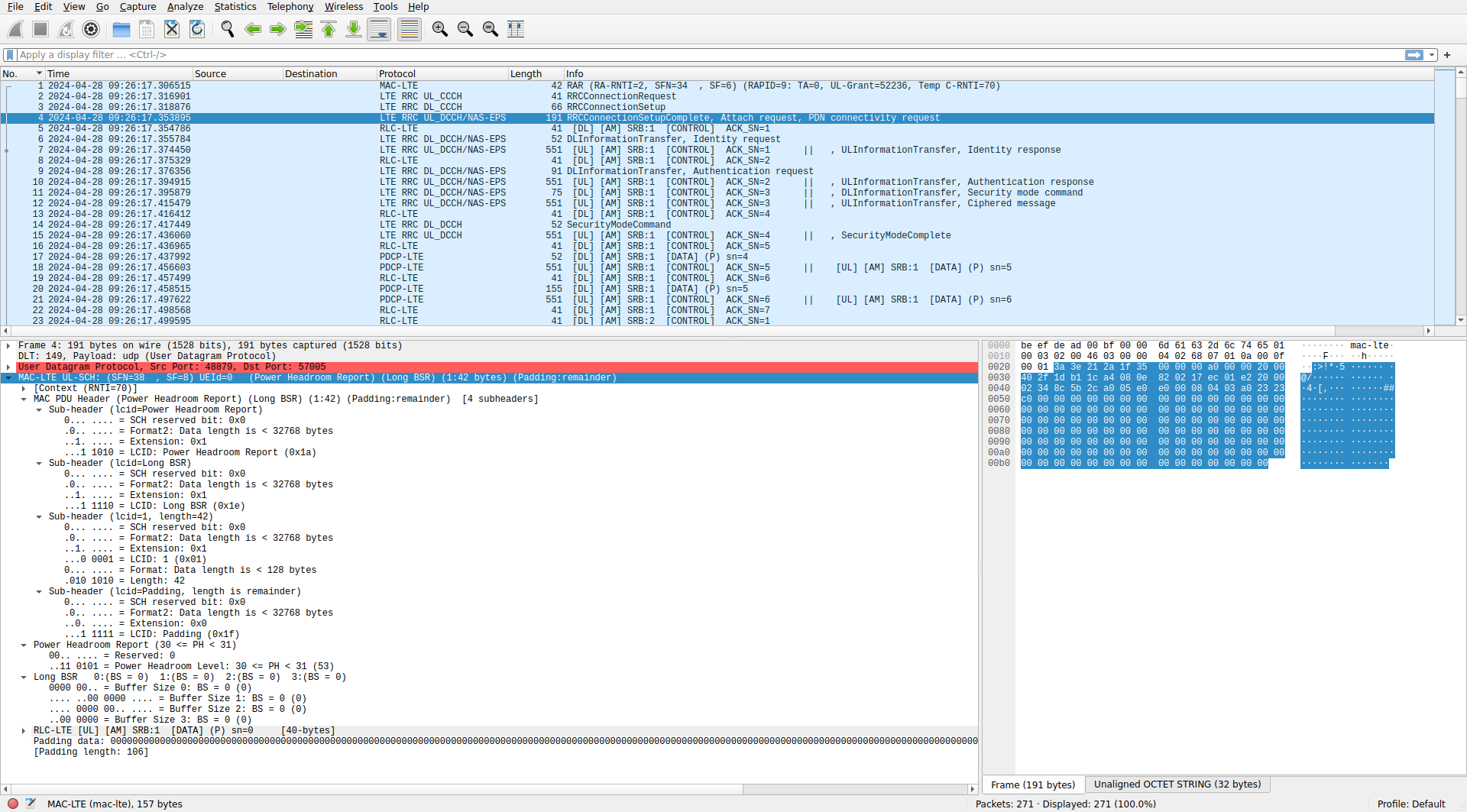
The RLC AM PDU is shown below. It has sequence number 0 (as expected, since it is the first one) and the polling flag enabled, meaning that an ACK is to be sent by the other end. This PDU contains a PDCP PDU which Wireshark knows to interpret as a DCCH (dedicated control channel) message. The sequence number of this PDCP PDU is also 0. The PDU contains an UL-DCCH message, which in this case is an RRC connection setup complete message. The message contains the PLMN ID (public land mobile network identifier, which is used to identify a carrier network, such as “Vodafone Spain”, or whatever), and a PDU for the NAS.
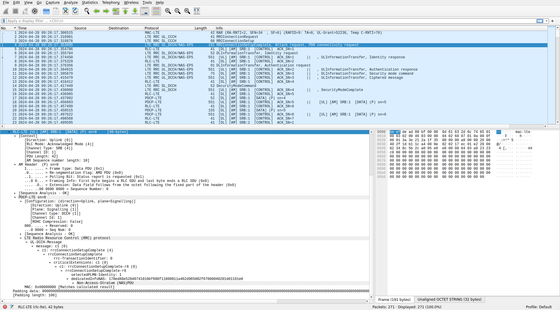
The PDU for the NAS is dissected by Wireshark, but it is long, so its contents are shown here as text. The PDU is a NAS attach request which also contains a PDN connectivity request to setup an IPv4 connection. The PDU contains identity information about the UE, including the TMSI that it has chosen. It also lists what encryption and integrity algorithms are supported by the UE.
Non-Access-Stratum (NAS)PDU
    0001 .... = Security header type: Integrity protected (1)
    .... 0111 = Protocol discriminator: EPS mobility management messages (0x7)
    Message authentication code: 0x8ed88e52
    Sequence number: 4
    0000 .... = Security header type: Plain NAS message, not security protected (0)
    .... 0111 = Protocol discriminator: EPS mobility management messages (0x7)
    NAS EPS Mobility Management Message Type: Attach request (0x41)
    0... .... = Type of security context flag (TSC): Native security context (for KSIasme or KSIamf)
    .000 .... = NAS key set identifier:  (0)
    .... 0... = Spare bit(s): 0x00
    .... .001 = EPS attach type: EPS attach (1)
    EPS mobile identity
        Length: 11
        .... 0... = Odd/even indication: Even number of identity digits
        .... .110 = Type of identity: GUTI (6)
        Mobile Country Code (MCC): Unknown (001)
        Mobile Network Code (MNC): Unknown (01)
        MME Group ID: 1
        MME Code: 26
        M-TMSI: 1177392720 (0x462d9650)
    UE network capability
        Length: 2
        1... .... = EEA0: Supported
        .1.. .... = 128-EEA1: Supported
        ..1. .... = 128-EEA2: Supported
        ...1 .... = 128-EEA3: Supported
        .... 0... = EEA4: Not supported
        .... .0.. = EEA5: Not supported
        .... ..0. = EEA6: Not supported
        .... ...0 = EEA7: Not supported
        0... .... = EIA0: Not supported
        .1.. .... = 128-EIA1: Supported
        ..1. .... = 128-EIA2: Supported
        ...1 .... = 128-EIA3: Supported
        .... 0... = EIA4: Not supported
        .... .0.. = EIA5: Not supported
        .... ..0. = EIA6: Not supported
        .... ...0 = EPS-UPIP: Not supported
    ESM message container
        Length: 4
        ESM message container contents: 0201d011
            0000 .... = EPS bearer identity: No EPS bearer identity assigned (0)
            .... 0010 = Protocol discriminator: EPS session management messages (0x2)
            Procedure transaction identity: 1
            NAS EPS session management messages: PDN connectivity request (0xd0)
            0001 .... = PDN type: IPv4 (1)
            .... 0001 = Request type: Initial request (1)
    TMSI Status
        1001 .... = Element ID: 0x9-
        .... 000. = Spare bit(s): 0
        .... ...1 = TMSI flag: valid TMSI available
    GUTI type - Old GUTI type
        1110 .... = Element ID: 0xe-
        .... 000. = Spare bit(s): 0x00
        .... ...0 = GUTI type: Native GUTI
The next MAC PDU is a downlink PDU that only contains an AM PDU in SRB 1 with an ACK sequence number of 1. This acknowledges the RRC connection setup complete sent by the UE (which had AM sequence number 0).
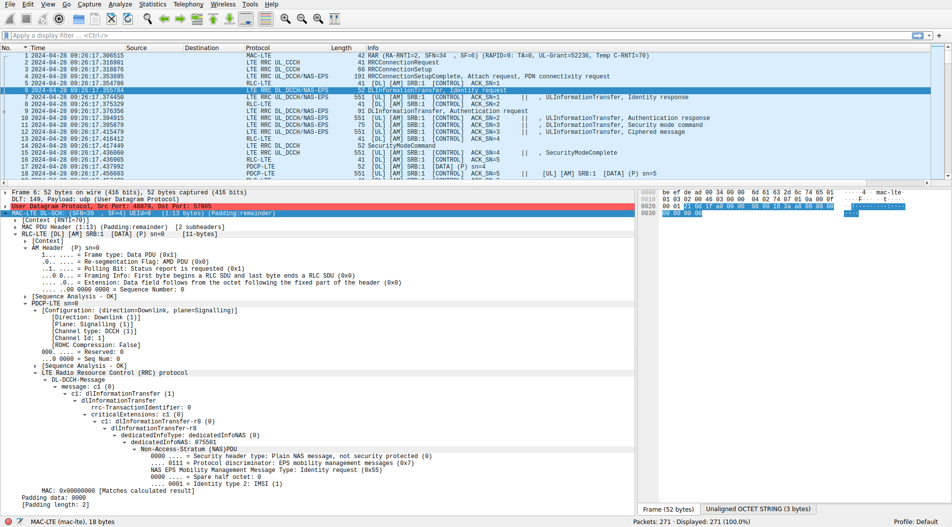
After this ACK, the eNB sends an AM PDU with sequence number 0 in SRB 1. This contains a PDCP PDU with a DL-DCCH message of type dlInformationTransfer, which just encapsulates a NAS PDU. The NAS PDU is an identity request asking the UE to report its IMSI.
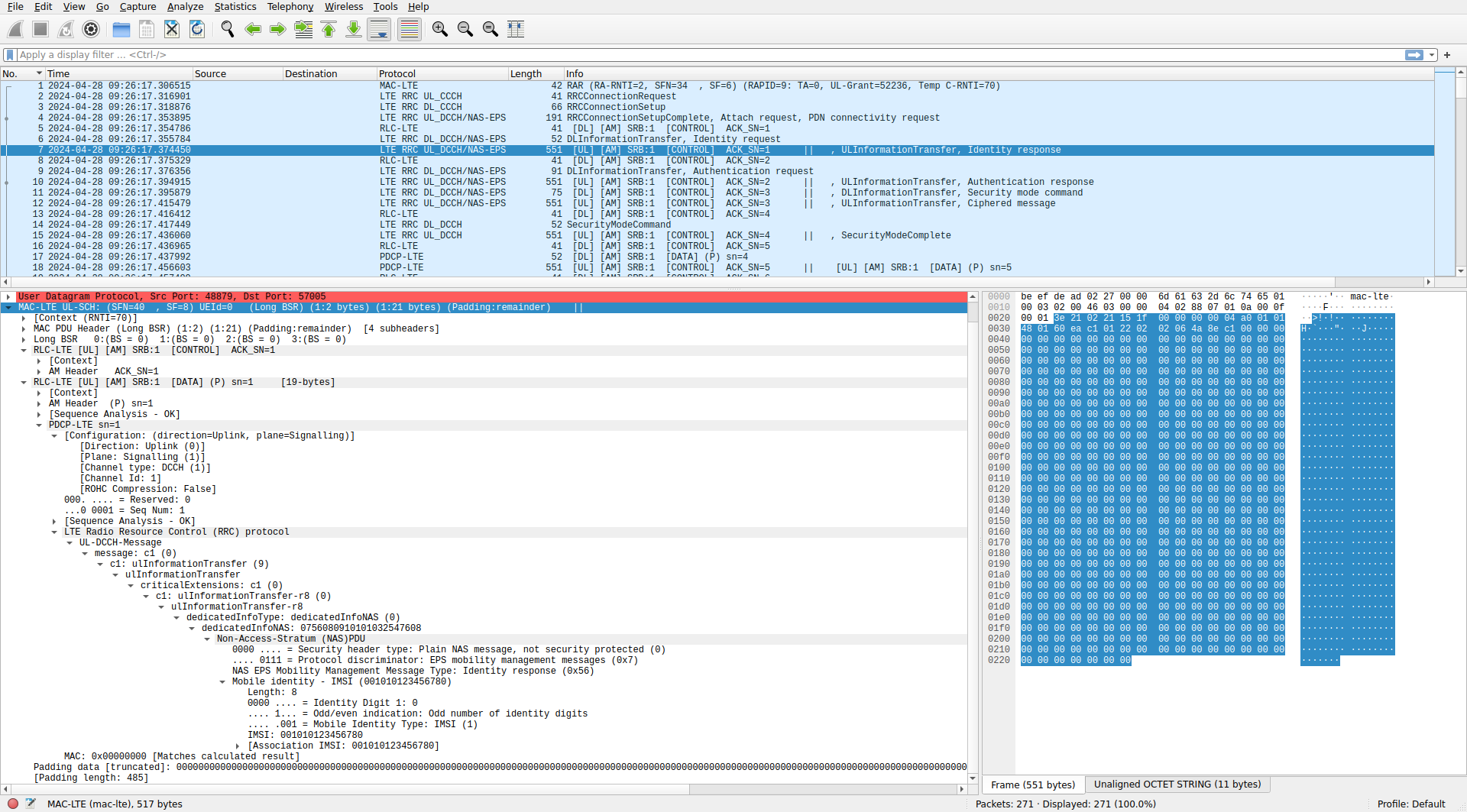
The UE replies with the following MAC PDU. It contains a long BSR control element and two RLC AM PDUs in SRB 1. The first of these PDUs is an ACK to the identity request PDU. The second PDU contains a PDCP PDU with an UL-DCCH message of type ulInformationTransfer. This encapsulates a NAS PDU. The NAS PDU is an identity response which contains the UE IMSI. Note that the IMSI is sent unencrypted. Encryption in LTE is based on symmetric algorithms, with keys derived from a key stored in the UE SIM. The EPC has a database of IMSIs and their corresponding keys, so before an encrypted connection is established, the UE needs to send its IMSI in the clear over the radio interface.
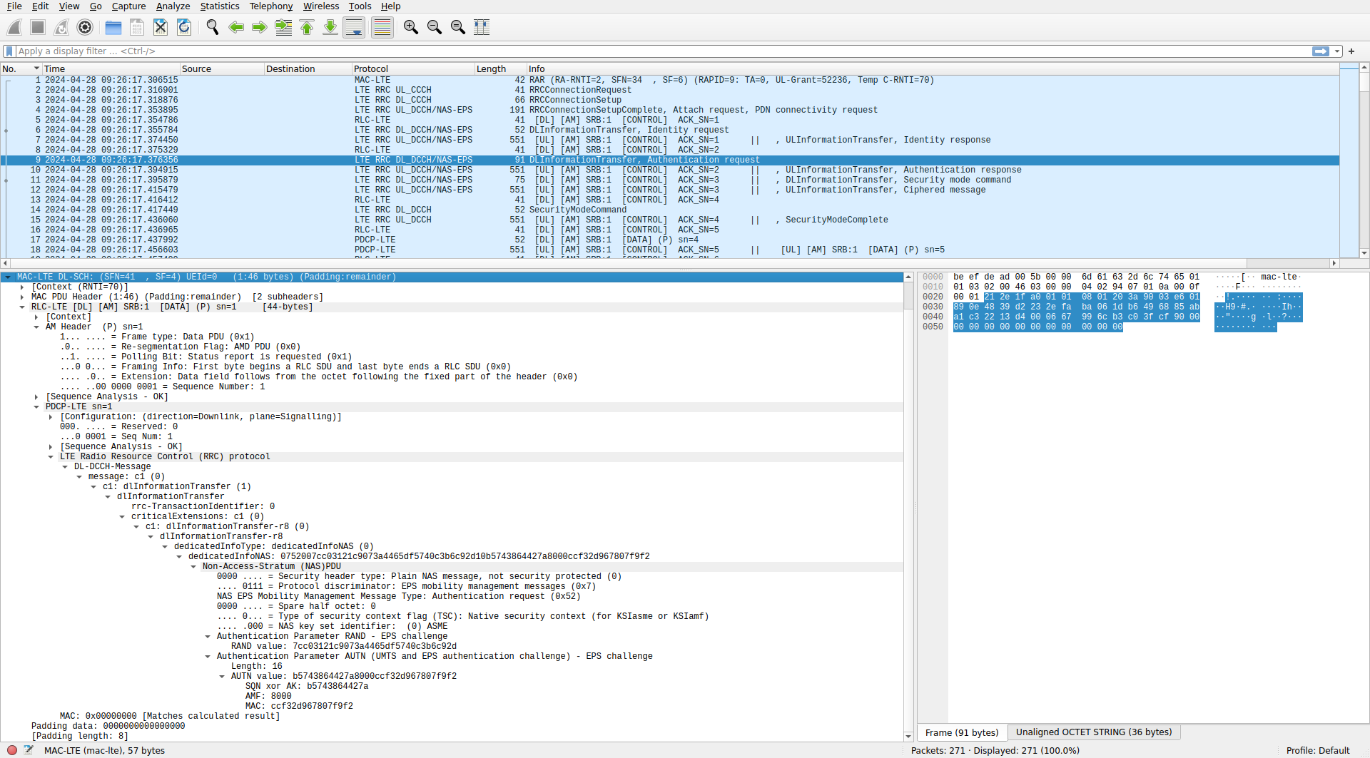
The next MAC PDU is a downlink ACK to this identity response. After this, there is another downlink MAC PDU. It contains a NAS PDU (encapsulated in the usual way as a DL-DCCH message). The NAS PDU is an authentication request. It contains some cryptographic parameters that the UE will use together with the key on its SIM (known both to the EPC and the UE) to prove its identity to the network.
Next the UE sends a MAC PDU with a long BSR control element an SRB 1 AM ACK to the authentication request, and an SRB 1 AM PDU that contains a NAS PDU with the authentication response. The authentication response contains some data that the EPC uses to verify that the UE has the correct SIM key.
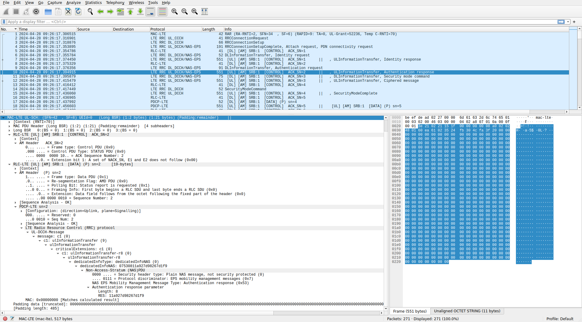
We can see more details about how the EPC processes the authentication response in the EPC log. As a consequence of the authentication success, the EPC derives keys for encryption and authentication of the NAS messages. It also derives a key that is sent to the eNB. The eNB will use that key to derive keys used for encryption and authentication of the UE data. The UE is able to derive all these keys as well.
2024-04-28T09:26:17.394978 [NAS    ] [I] Authentication Response -- IMSI 001010123456780
2024-04-28T09:26:17.394978 [NAS    ] [I] Authentication response -- RES
    0000: 11 a9 27 d9 82 67 d1 f9
2024-04-28T09:26:17.394978 [NAS    ] [I] Authentication response -- XRES
    0000: 11 a9 27 d9 82 67 d1 f9
2024-04-28T09:26:17.394982 [NAS    ] [I] UE Authentication Accepted.
2024-04-28T09:26:17.394982 [NAS    ] [I] Packing Security Mode Command
2024-04-28T09:26:17.394989 [NAS    ] [I] Key NAS Encryption (k_nas_enc)
    0000: 28 45 f9 66 04 7d bf e1 0c d8 e2 1f b4 bc 5b 84
    0010: 64 d6 4c b0 23 98 12 b1 03 3b 0f b8 c9 ee 64 b2
2024-04-28T09:26:17.394989 [NAS    ] [I] Key NAS Integrity (k_nas_int)
    0000: 25 03 d8 c3 4f bc 3e 52 c4 33 9d 8d c2 67 e5 72
    0010: c9 61 e5 1d cd a8 ad d8 6d ed 30 e2 5b 19 01 94
2024-04-28T09:26:17.394991 [NAS    ] [I] Generating KeNB with UL NAS COUNT: 0
2024-04-28T09:26:17.394993 [NAS    ] [I] Key eNodeB (k_enb)
    0000: 84 93 0d 19 02 5c 39 8c 21 ee 66 01 3c 00 59 aa
    0010: c6 27 84 93 da a9 da ed f4 26 ec e9 76 f9 60 95
Now there is a downlink MAC PDU that contains an SRB 1 AM ACK and an SRB 1 AM PDU with a NAS PDU. The NAS PDU is a security mode command that selects the usage of EEA2 (AES-128) for encryption and EEA1 (SNOW3) for integrity. This matches the settings that we have in epc.conf. The NAS PDU also replays the UE security capabilities.
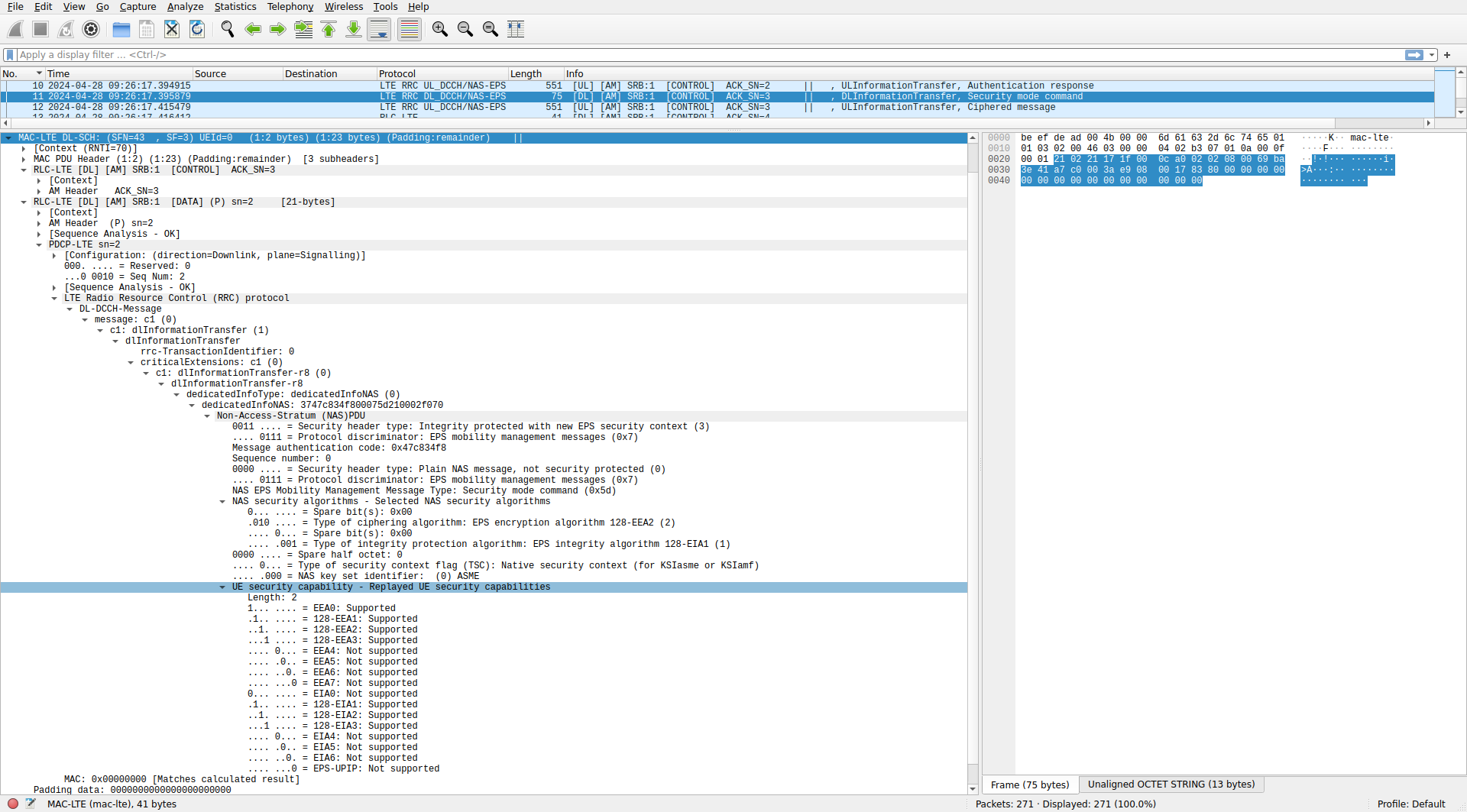
The UE replies with a MAC PDU that contains a power headroom and a long BSR control element, an SRB 1 AM ACK, and an SRB 1 AM PDU containing a NAS PDU. The NAS PDU now contains a ciphered message, since the EPC has configured encryption for the NAS communications.
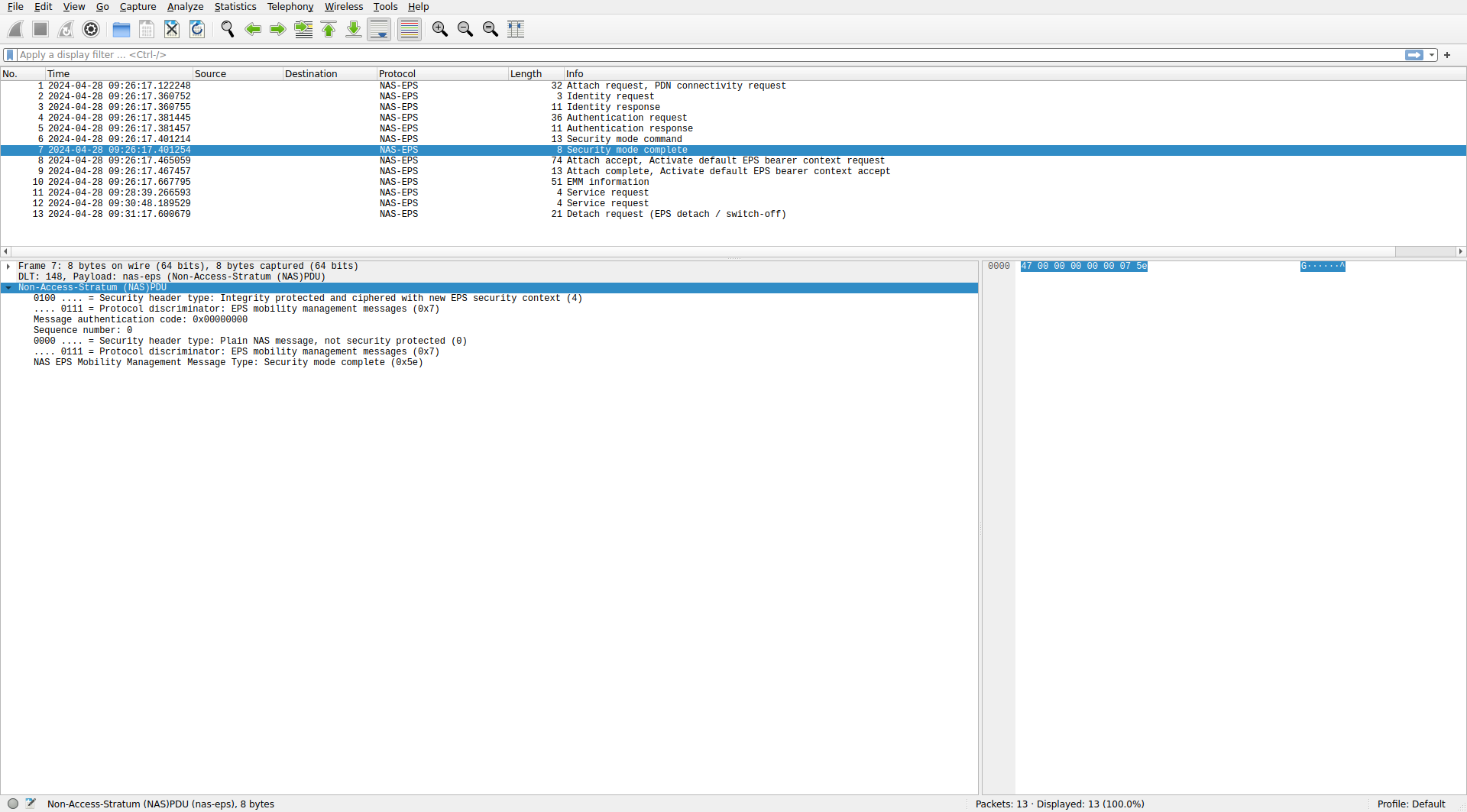
It doesn’t seem that Wireshark is capable of decrypting NAS messages, even if we have the encryption key. The epc.pcap contains the same NAS PDU, with the message encrypted (but the PDU is encapsulated in an S1AP packet instead of a MAC PDU), so we can’t cheat by looking there. However, there is also a ue_nas.pcap file in which all the NAS PDUs are unencrypted, so we can cheat and look there.
The unencrypted NAS PDU is shown here. It is a security mode complete message, confirming that encryption and integrity has been configured as indicated by the EPC. Compare this view of the NAS PDU with the NAS PDU that was sent over the air. The first fields are the same, except that in the ue_nas.pcap NAS PDU the message authentication code is still filled with zeros because it has not been calcualted yet. After these fields, we have two bytes of encrypted data 0x688e in the NAS PDU sent over the air. In the ue_nas.pcap NAS PDU we can see that these correspond to the unencrypted bytes 0x075e, which are on its own a NAS message that indicates that it is unencrypted and that it is a security mode complete EPS mobility management message.
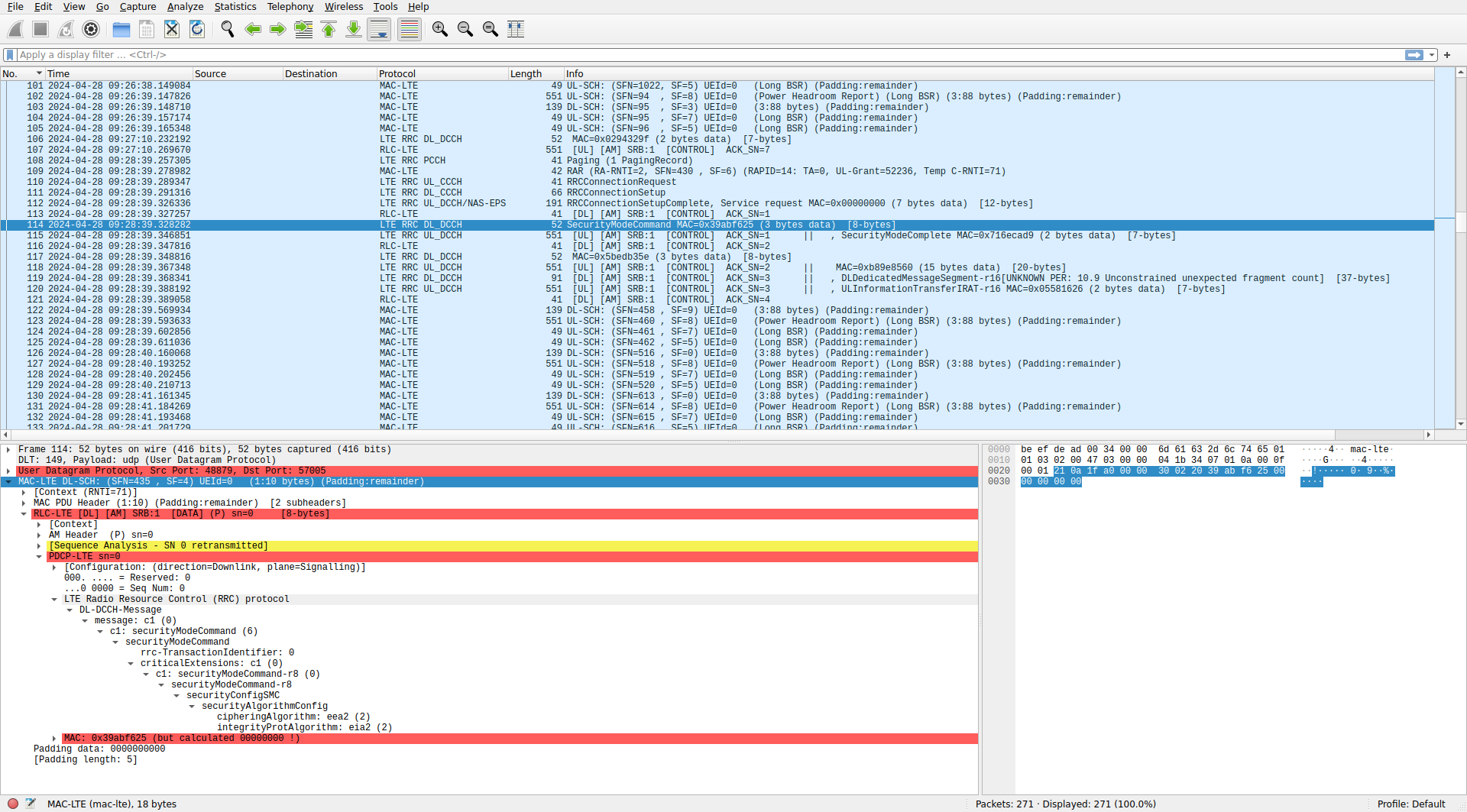
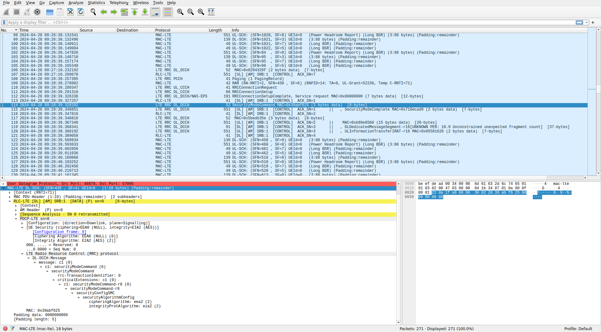
After the security mode complete NAS PDU, there is a downlink PDU that contains an AM ACK for this message. Then a downlink MAC PDU is sent with an SRB 1 AM PDU that contains a DL-DCCH message of type securityModeCommand. This configures encryption and integrity for the RRC communications between the UE and the eNB. The command selects the use of EEA2 (AES-128) and EIA2 (AES-128) for encryption and authentication respectively. This is what we have chosen in enb.conf as preferred algorithms.
The UE replies to this message with a MAC PDU that contains a long BSR control element, an SRB 1 AM ACK, and an SRB 1 AM PDU containing an UL-DCCH message of type security mode complete. From this point on, RRC communications will be encrypted.
The next MAC PDU is a downlink ACK for the RRC security mode complete message. After this, there is a downlink MAC PDU that contains an SRB 1 AM PDU. The AM PDU contains a PDCP PDU, but its payload is encrypted, so Wireshark displays the payload as “Signalling Data” (and as [DATA] in the packet list), instead of dissecting its contents.
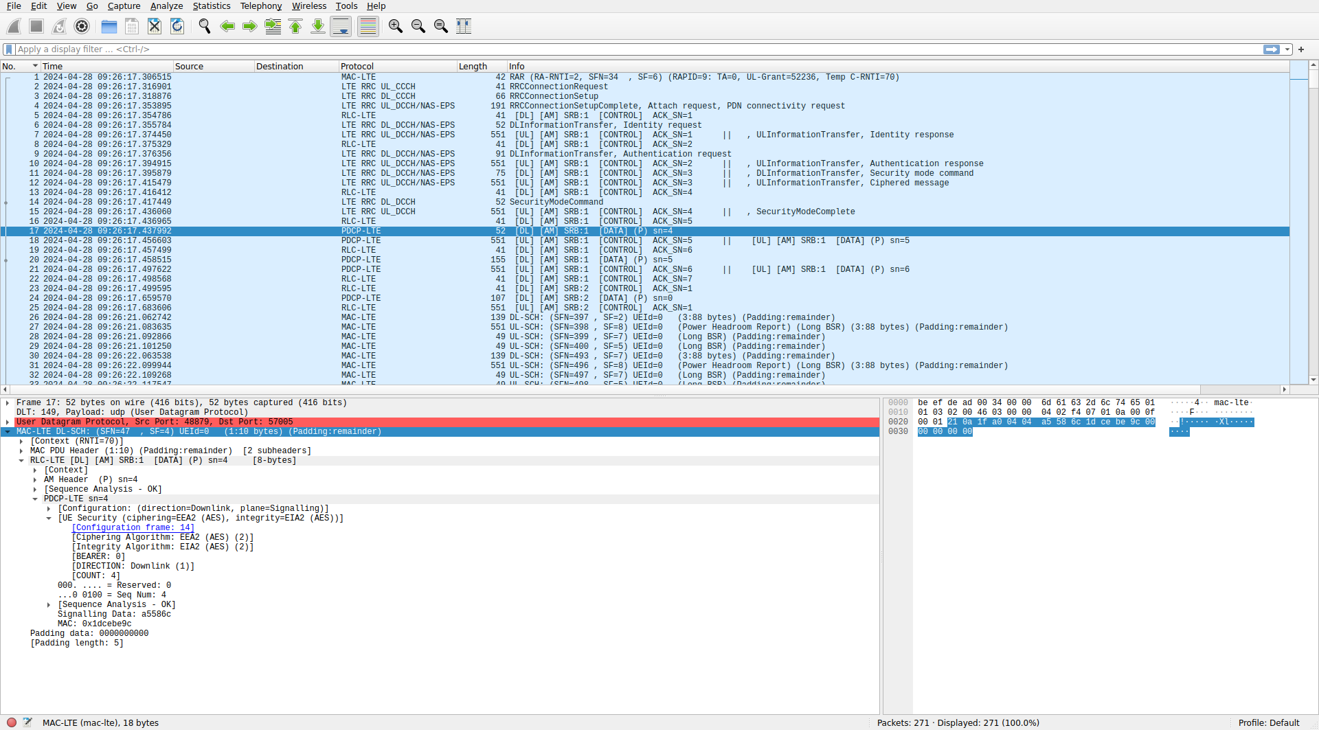
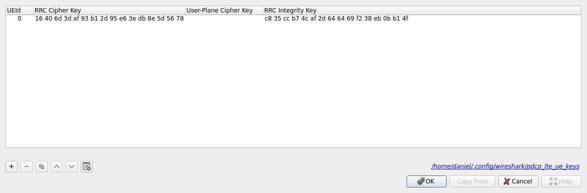
Wireshark knows the encryption parameters (and displays them as the [UE Security] context), because it has seen the RRC security mode commmand. To decrypt the payload we need to supply the encryption key. This is done with the “PDCP UE keys…” option in the PDCP protocol preferences. We can obtain these keys from the UE log:
2024-04-28T09:26:17.422920 [PDCP   ] [I] Configuring security with 128-EIA2 and 128-EEA2
2024-04-28T09:26:17.422920 [PDCP   ] [D] K_rrc_enc
    0000: 24 3c 96 ed 13 64 12 2c 77 dd 8c 66 c1 79 f7 da
    0010: 16 40 6d 3d af 93 b1 2d 95 e6 3e db 8e 5d 56 78
2024-04-28T09:26:17.422920 [PDCP   ] [D] K_up_enc
    0000: d5 3a 44 43 6c 7b c0 3f 46 e3 29 0a d3 79 e7 da
    0010: 99 64 23 91 8a ec cd a0 3b 34 8a c3 73 1c 01 77
2024-04-28T09:26:17.422921 [PDCP   ] [D] K_rrc_int
    0000: 6e 5a 3d ea fc 74 08 70 91 30 dc e5 84 fc 5f 25
    0010: c8 35 cc b7 4c af 2d 64 64 69 f2 38 eb 0b b1 4f
2024-04-28T09:26:17.422921 [PDCP   ] [D] K_up_int
    0000: 55 16 11 75 4b 4a c6 1d 99 94 21 34 3e 32 e2 3a
    0010: 5a 76 11 c6 73 2e 36 ff 84 f6 0f 41 0c 21 94 07
The keys shown in the log are 256-bits long. However, Wireshark expects only 128 bits. To see how to proceed here, we can look at the source code of the cipher_encrypt() function in srsRAN and other similar functions in the same file and note that they only use the last 16 bytes of the 32-byte key. I don’t know why this is done, but I guess that LTE has the provision for cryptographic algorithms using 256-bit keys and internally it derives 256-bit keys and specifies that algorithms with 128-bit keys should only use the last 128 bits.
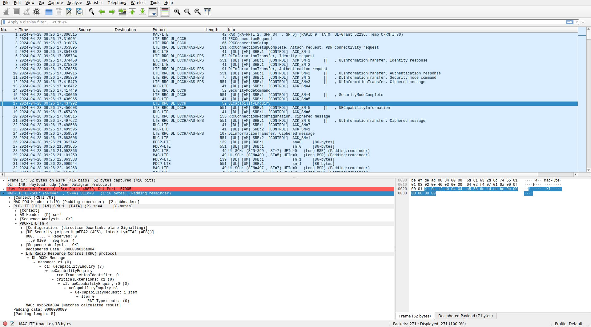
For the moment I will only enter the RRC encryption and integrity keys into Wireshark, to show what happens with encrypted user data when the key is missing. Wireshark needs the UEId for the keys. This is an ID that is assigned to the UE in the metadata of MAC PDU frames, using an optional header field in the encapsulation of MAC PDUs into UDP packets. I think the UEId is missing from these MAC PDUs (or at least Wireshark doesn’t show it in the [Context]), so Wireshark assigns UEId = 0 to this UE.
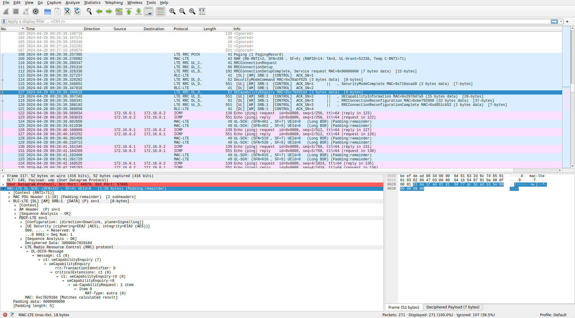
Once the RRC keys are configured, the payload of the PDCP PDU is decrypted and dissected as a DL-DCCH message. The message is a UE capability request. In the list of packets we can see that packets 26 and below, which were originally displayed just as SDUs in LCID 3 are now displayed as RLC UM PDUs in DRB 1, because Wireshark is now able to read the configuration message for this LCID (this happens a few packets below the point we’re currently at). Also note that Wireshark is checking that the message authentication code of the PDCP PDUs is correct.
The UE replies with a MAC PDU that contains a long BSR, an AM ACK, and an SRB 1 AM PDU with an UL-DCCH message of type capability information.
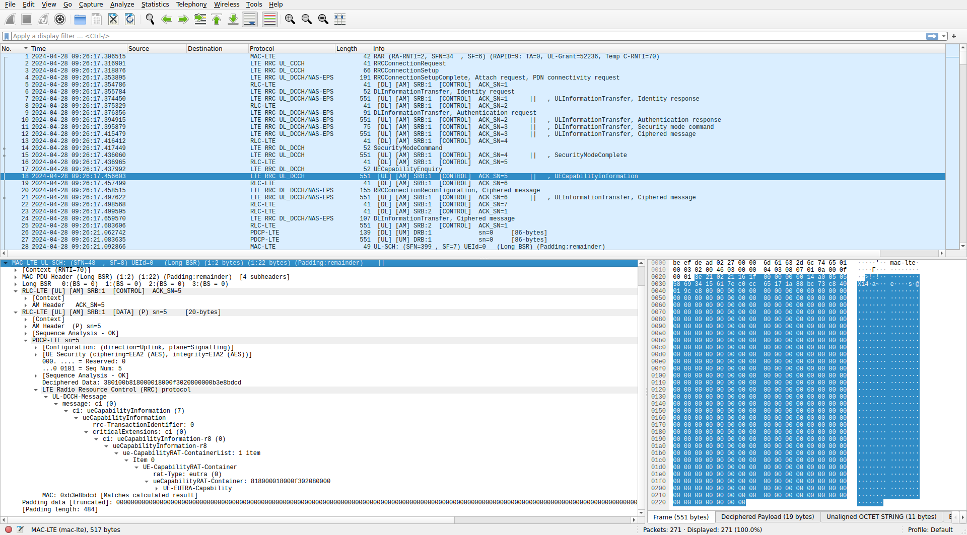
The capabilities of the UE are quite long, so their dissection is shown here in text. We can see that the srsRAN UE application doesn’t support many advanced features.
UE-EUTRA-Capability
    accessStratumRelease: rel8 (0)
    ue-Category: 4
    pdcp-Parameters
        supportedROHC-Profiles
            ...0 .... profile0x0001-r15: False
            .... 0... profile0x0002-r15: False
            .... .0.. profile0x0003-r15: False
            .... ..0. profile0x0004-r15: False
            .... ...0 profile0x0006-r15: False
            0... .... profile0x0101-r15: False
            .0.. .... profile0x0102-r15: False
            ..0. .... profile0x0103-r15: False
            ...0 .... profile0x0104-r15: False
    phyLayerParameters
        .... 0... ue-TxAntennaSelectionSupported: False
        .... .0.. ue-SpecificRefSigsSupported: False
    rf-Parameters
        supportedBandListEUTRA: 1 item
            Item 0
                SupportedBandEUTRA
                    bandEUTRA: 7
                    ..0. .... halfDuplex: False
    measParameters
        bandListEUTRA: 1 item
            Item 0
                BandInfoEUTRA
                    interFreqBandList: 1 item
                        Item 0
                            InterFreqBandInfo
                                1... .... interFreqNeedForGaps: True
                            [bandEUTRA: 7 -> band 7]
    featureGroupIndicators: e6041000 [bit length 32, 1110 0110  0000 0100  0001 0000  0000 0000 decimal value 3859025920]
        1... .... = Indicator 1: Intra-subframe freq hopping for PUSCH scheduled by UL grant; DCI format 3a; Aperiodic CQI/PMI/RI report on PUSCH: Mode 2-0 & 2-2 - Supported
        .1.. .... = Indicator 2: Simultaneous CQI & ACK/NACK on PUCCH (format 2a/2b); Absolute TPC command for PUSCH; Resource alloc type 1 for PDSCH; Periodic CQI/PMI/RI report on PUCCH: Mode 2-0 & 2-1 - Supported
        ..1. .... = Indicator 3: 5bit RLC UM SN; 7bit PDCP SN - Supported
        ...0 .... = Indicator 4: Short DRX cycle - Not supported
        .... 0... = Indicator 5: Long DRX cycle; DRX command MAC control element - Not supported
        .... .1.. = Indicator 6: Prioritised bit rate - Supported
        .... ..1. = Indicator 7: RLC UM - Supported
        .... ...0 = Indicator 8: EUTRA RRC_CONNECTED to UTRA CELL_DCH PS handover - Not supported
        0... .... = Indicator 9: EUTRA RRC_CONNECTED to GERAN GSM_Dedicated handover - Not Supported
        .0.. .... = Indicator 10: EUTRA RRC_CONNECTED to GERAN (Packet_) Idle by Cell Change Order; EUTRA RRC_CONNECTED to GERAN (Packet_) Idle by Cell Change Order with NACC - Not supported
        ..0. .... = Indicator 11: EUTRA RRC_CONNECTED to CDMA2000 1xRTT CS Active handover - Not supported
        ...0 .... = Indicator 12: EUTRA RRC_CONNECTED to CDMA2000 HRPD Active handover - Not supported
        .... 0... = Indicator 13: Inter-frequency handover (within FDD or TDD) - Not supported
        .... .1.. = Indicator 14: Measurement reporting event: Event A4 - Neighbour > threshold; Measurement reporting event: Event A5 - Serving < threshold1 & Neighbour > threshold2 - Supported
        .... ..0. = Indicator 15: Measurement reporting event: Event B1 - Neighbour > threshold - Not supported
        .... ...0 = Indicator 16: non-ANR related periodical measurement reporting - Not supported
        0... .... = Indicator 17: ANR related intra-frequency measurement reporting events - Not supported
        .0.. .... = Indicator 18: ANR related inter-frequency measurement reporting events - Not supported
        ..0. .... = Indicator 19: ANR related inter-RAT measurement reporting events - Not supported
        ...1 .... = Indicator 20: SRB1 and SRB2 for DCCH + 8x AM DRB; SRB1 and SRB2 for DCCH + 5x AM DRB + 3x UM DRB (if indicator 7 is supported) - Supported
        .... 0... = Indicator 21: Predefined intra- and inter-subframe frequency hopping for PUSCH with N_sb > 1; Predefined inter-subframe frequency hopping for PUSCH with N_sb > 1 - Not supported
        .... .0.. = Indicator 22: UTRAN measurements, reporting and measurement reporting event B2 in E-UTRA connected mode - Not supported
        .... ..0. = Indicator 23: GERAN measurements, reporting and measurement reporting event B2 in E-UTRA connected mode - Not supported
        .... ...0 = Indicator 24: 1xRTT measurements, reporting and measurement reporting event B2 in E-UTRA connected mode - Not supported
        0... .... = Indicator 25: Inter-frequency measurements and reporting in E-UTRA connected mode - Not supported
        .0.. .... = Indicator 26: HRPD measurements, reporting and measurement reporting event B2 in E-UTRA connected mode - Not supported
        ..0. .... = Indicator 27: EUTRA RRC_CONNECTED to UTRA CELL_DCH CS handover - Not supported
        ...0 .... = Indicator 28: TTI bundling - Not supported
        .... 0... = Indicator 29: Semi-Persistent Scheduling - Not supported
        .... .0.. = Indicator 30: Handover between FDD and TDD - Not supported
        .... ..0. = Indicator 31: Mechanisms defined for cells broadcasting multi band information - Not supported
        .... ...0 = Indicator 32: Undefined - Not supported
    interRAT-Parameters
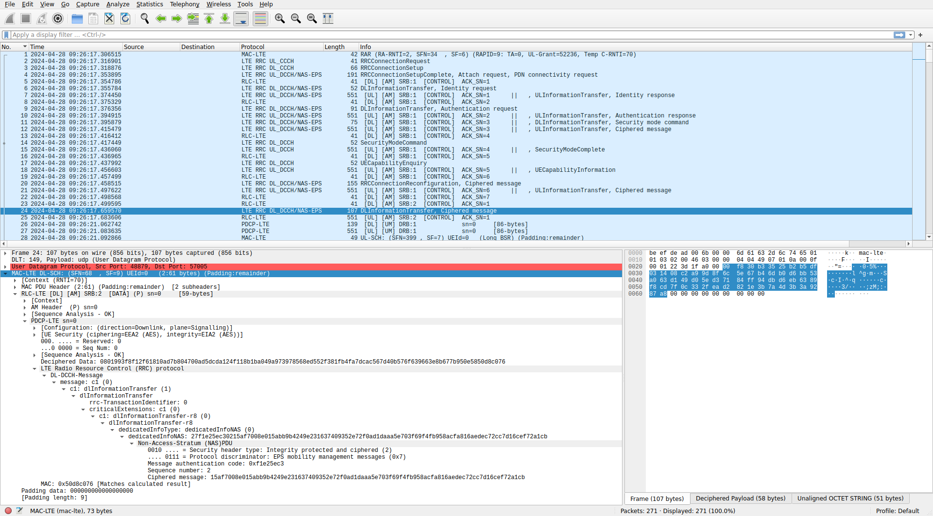
After the UE capability information there is a downlink MAC PDU with an SRB 1 AM ACK. The next MAC PDU is a downlink SRB 1 AM PDU that contains a DL-DCCH message of type RRC connection reconfiguration. This is shown here, but the dissection of the connection reconfiguration is too long, so it shown below as text. Note that the connection reconfiguration message carries a NAS PDU that contains a ciphered message.
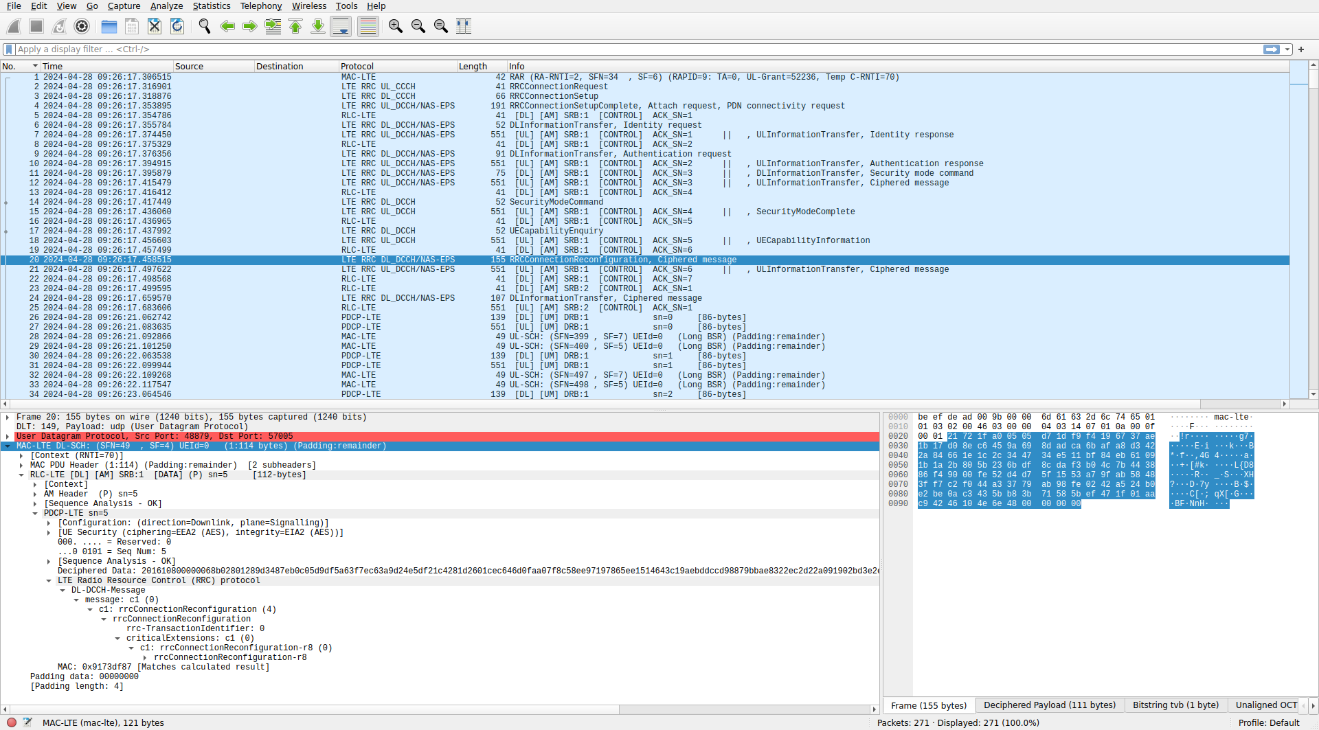
The RRC connection reconfiguration configures the UE measurements of cell signal quality. It also enables additional radio bearers: SRB 2, which implicitly uses the RLC AM protocol and LCID 2, and DRB 1, which is configured with LCID 3 and the RLC UM protocol with a sequence number length of 10 bits in both directions. PDCP header compression is disabled (the srsUE has stated that it doesn’t suport it), and a 12 bit sequence number is configured. DRB 1 is associated with EPS bearer 5, which is enabled in the embedded NAS PDU. The physicalConfigDedicated message that already appeared in the RRC connection setup message is now repeated.
rrcConnectionReconfiguration-r8
    measConfig
        measObjectToAddModList: 1 item
            Item 0
                MeasObjectToAddMod
                    measObjectId: 1
                    measObject: measObjectEUTRA (0)
                        measObjectEUTRA
                            carrierFreq: 3350
                            allowedMeasBandwidth: mbw6 (0)
                            .... 0... presenceAntennaPort1: False
                            neighCellConfig: No MBSFN subframes are present in all neighbour cells (1)
        quantityConfig
            quantityConfigEUTRA
    dedicatedInfoNASList: 1 item
        Item 0
            DedicatedInfoNAS: 274d21fac3017677d698fdfb18ea7493977c8710a07498073b191b43ea81fe3163ba5c65e197b8545190f066baf77336621e6eeba0c8bb0b48a824640af4f8ba6e09f3a1be3272157383
                Non-Access-Stratum (NAS)PDU
                    0010 .... = Security header type: Integrity protected and ciphered (2)
                    .... 0111 = Protocol discriminator: EPS mobility management messages (0x7)
                    Message authentication code: 0x4d21fac3
                    Sequence number: 1
                    Ciphered message: 7677d698fdfb18ea7493977c8710a07498073b191b43ea81fe3163ba5c65e197b8545190f066baf77336621e6eeba0c8bb0b48a824640af4f8ba6e09f3a1be3272157383
    radioResourceConfigDedicated
        srb-ToAddModList: 1 item
            Item 0
                SRB-ToAddMod
                    srb-Identity: 2
                    rlc-Config: defaultValue (1)
                        defaultValue: NULL
                    logicalChannelConfig: defaultValue (1)
                        defaultValue: NULL
        drb-ToAddModList: 1 item
            Item 0
                DRB-ToAddMod
                    eps-BearerIdentity: 5
                    drb-Identity: 1
                    pdcp-Config
                        discardTimer: infinity (7)
                        rlc-UM
                            pdcp-SN-Size: len12bits (1)
                        headerCompression: notUsed (0)
                            notUsed: NULL
                    rlc-Config: um-Bi-Directional (1)
                        um-Bi-Directional
                            ul-UM-RLC
                                sn-FieldLength: size10 (1)
                            dl-UM-RLC
                                sn-FieldLength: size10 (1)
                                t-Reordering: ms45 (9)
                    logicalChannelIdentity: 3
                    logicalChannelConfig
                        ul-SpecificParameters
                            priority: 13
                            prioritisedBitRate: infinity (7)
                            bucketSizeDuration: ms100 (1)
                            logicalChannelGroup: 2
        physicalConfigDedicated
            pdsch-ConfigDedicated
                p-a: dB0 (4)
            pucch-ConfigDedicated
                ackNackRepetition: release (0)
                    release: NULL
            pusch-ConfigDedicated
                betaOffset-ACK-Index: 6
                betaOffset-RI-Index: 6
                betaOffset-CQI-Index: 6
            uplinkPowerControlDedicated
                p0-UE-PUSCH: 0 dB
                deltaMCS-Enabled: en0 (0)
                ...1 .... accumulationEnabled: True
                p0-UE-PUCCH: 0 dB
                pSRS-Offset: 3
            cqi-ReportConfig
                nomPDSCH-RS-EPRE-Offset: 0dB (0)
                cqi-ReportPeriodic: setup (1)
                    setup
                        cqi-PUCCH-ResourceIndex: 0
                        cqi-pmi-ConfigIndex: 38
                        cqi-FormatIndicatorPeriodic: widebandCQI (0)
                            widebandCQI: NULL
                        .1.. .... simultaneousAckNackAndCQI: True
            antennaInfo: explicitValue (0)
                explicitValue
                    transmissionMode: tm1 (0)
                    ue-TransmitAntennaSelection: release (0)
                        release: NULL
            schedulingRequestConfig: setup (1)
                setup
                    sr-PUCCH-ResourceIndex: 0
                    sr-ConfigIndex: 15
                        [Periodicity: 20]
                        [Subframe Offset: 0]
                    dsr-TransMax: n64 (4)
Going to ue_nas.pcap, we see that the encrypted NAS PDU is an attach accept message. The dissection of the NAS PDU is long, so it is shown here as text. Note that in this case the UE has recorded to the PCAP the message authentication code as it has come over the air. Also note that NAS PDUs have the message authentication code outside of the encrypted data, whereas in PDCP PDUs the message authentication code is inside the encrypted data. Among other things, the attach accept contains an ESM message that activates EPS bearer 5 for IP data services. This bearer ID matches the one assigned to DRB 1. The ESM message contains the APN, the IPv4 address assigned to the UE (127.16.0.2), and a DNS server (8.8.8.8). Additionally, the attach accept contains a new M-TMSI for the UE: 0x22bd2ec4. Note that this is different from the M-TMSI 0x462d9650 that we have seen in the RRC connection request and NAS attach request messages. The new TMSI is set as a security measure. Even though the UE initially needs to send a TMSI and its IMSI in the clear in the initial connection, once an encrypted NAS connection is established, the UE gets a new TMSI from the network over the encrypted connection, preventing eavesdroppers from keeping track of the mapping between IMSIs and TMSIs.
Non-Access-Stratum (NAS)PDU
    0010 .... = Security header type: Integrity protected and ciphered (2)
    .... 0111 = Protocol discriminator: EPS mobility management messages (0x7)
    Message authentication code: 0x4d21fac3
    Sequence number: 1
    0000 .... = Security header type: Plain NAS message, not security protected (0)
    .... 0111 = Protocol discriminator: EPS mobility management messages (0x7)
    NAS EPS Mobility Management Message Type: Attach accept (0x42)
    0000 .... = Spare half octet: 0
    .... 0... = Spare bit(s): 0x00
    .... .001 = Attach result: EPS only (1)
    GPRS Timer - T3412 value
        GPRS Timer: 30 min
            001. .... = Unit: value is incremented in multiples of 1 minute (1)
            ...1 1110 = Timer value: 30
    Tracking area identity list - TAI list
        Length: 6
        0... .... = Spare bit(s): 0x00
        .00. .... = Type of list: list of TACs belonging to one PLMN, with non-consecutive TAC values (0)
        ...0 0000 = Number of elements: 0 [+1 = 1 element(s)]
        Mobile Country Code (MCC): Unknown (001)
        Mobile Network Code (MNC): Unknown (01)
        Tracking area code(TAC): 7
    ESM message container
        Length: 29
        ESM message container contents: 5201c10107070673727361706e0501ac100002270880000d0408080808
            0101 .... = EPS bearer identity: EPS bearer identity value 5 (5)
            .... 0010 = Protocol discriminator: EPS session management messages (0x2)
            Procedure transaction identity: 1
            NAS EPS session management messages: Activate default EPS bearer context request (0xc1)
            EPS quality of service
                Length: 1
                Quality of Service Class Identifier (QCI): QCI 7 (7)
            Access Point Name
                Length: 7
                APN: srsapn
            PDN address
                Length: 5
                0000 0... = Spare bit(s): 0x00
                PDN type: IPv4 (1)
                PDN IPv4: 172.16.0.2
            Protocol Configuration Options
                Element ID: 0x27
                Length: 8
                [Link direction: Network to MS (1)]
                1... .... = Extension: True
                .... .000 = Configuration Protocol: PPP for use with IP PDP type or IP PDN type (0)
                Protocol or Container ID: DNS Server IPv4 Address (0x000d)
                    Length: 0x04 (4)
                    IPv4: 8.8.8.8
    EPS mobile identity - GUTI
        Element ID: 0x50
        Length: 11
        .... 0... = Odd/even indication: Even number of identity digits
        .... .110 = Type of identity: GUTI (6)
        Mobile Country Code (MCC): Unknown (001)
        Mobile Network Code (MNC): Unknown (01)
        MME Group ID: 1
        MME Code: 26
        M-TMSI: 582823620 (0x22bd2ec4)
    Location area identification
        Element ID: 0x13
        Location Area Identification (LAI) - MCC 1 , MNC 01 , LAC 6
            Mobile Country Code (MCC): Unknown (001)
            Mobile Network Code (MNC): Unknown (01)
            Location Area Code (LAC): 0x0006 (6)
    Mobile identity - MS identity - TMSI/P-TMSI (0x22bd2ec4)
        Element ID: 0x23
        Length: 5
        1111 .... = Unused: 0xf
        .... 0... = Odd/even indication: Even number of identity digits
        .... .100 = Mobile Identity Type: TMSI/P-TMSI/M-TMSI (4)
        TMSI/P-TMSI/M-TMSI/5G-TMSI: 582823620 (0x22bd2ec4)
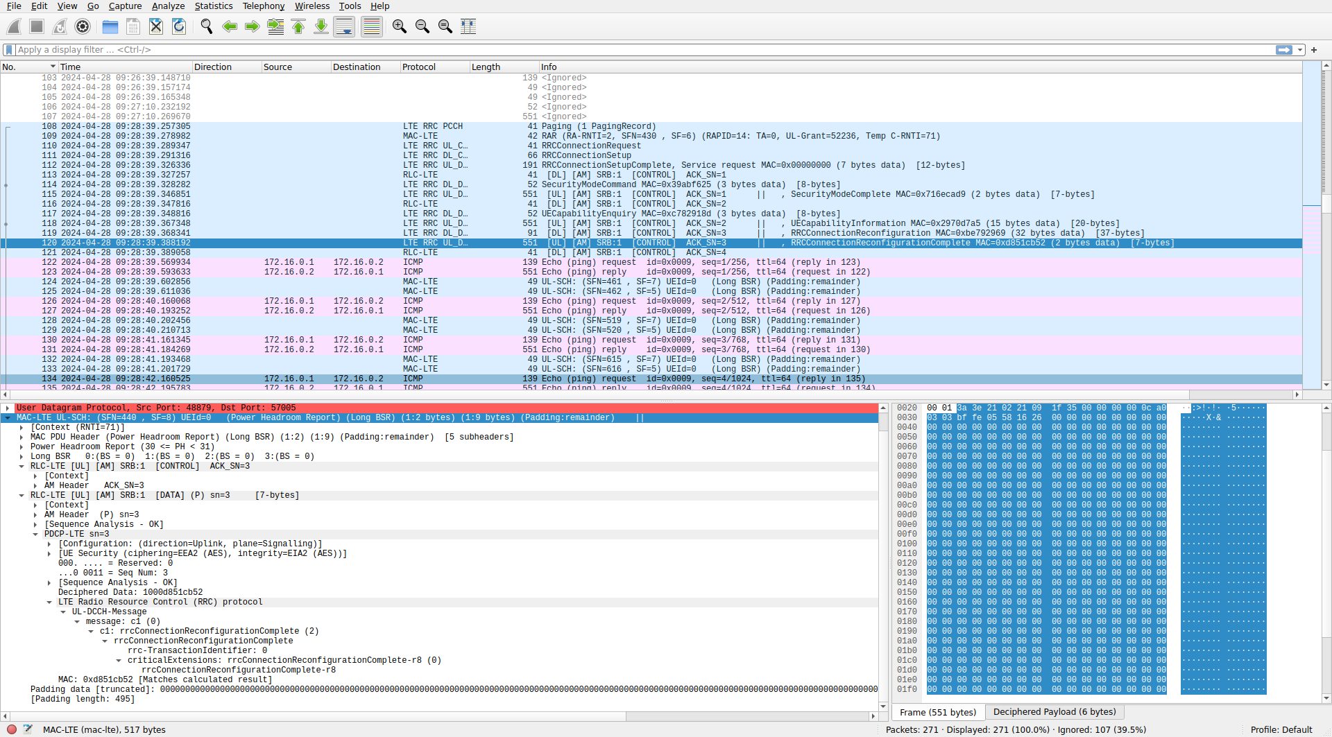
The UE replies to the RRC connection reconfiguration with a MAC PDU that contains many elements. There are power headroom and long BSR control elements. Then there is an SRB 1 AM ACK for the RRC connection reconfiguration. Then there is an SRB 1 AM PDU that contains an UL-DCCH message of type RRC connection reconfiguration complete. This acknowledges the reconfiguration at the RRC layer level. Finally there is an SRB 2 AM PDU that contains an encrypted NAS PDU. SRB 2 has lower priority than SRB 1 and is typically used for control communications after it has been established using SRB 1.
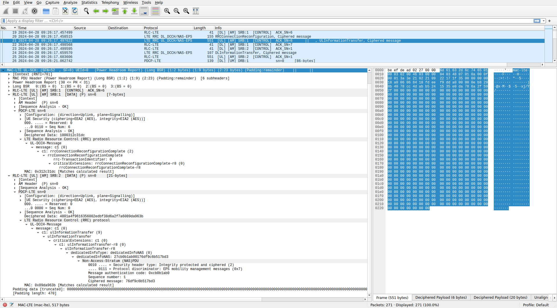
Going to the ue_nas.pcap file, we see that the encrypted NAS PDU is an attach complete message. This simply acknowledges and accepts the EPS bearer that was configured in the attach accept message.
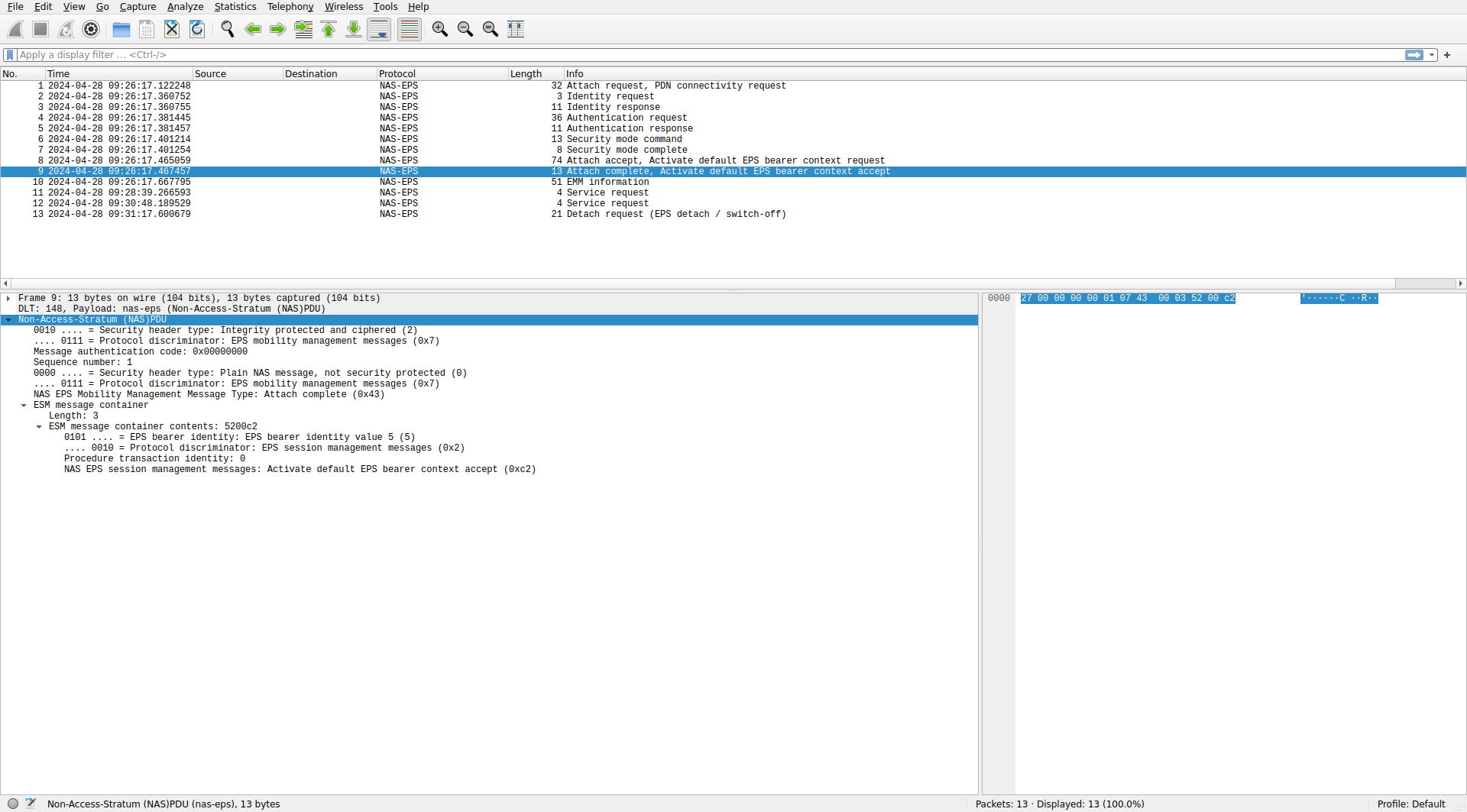
The eNB now sends two MAC PDUs, each containing an AM ACK for SRB 1 and SRB 2 respectively. Then it sends another MAC PDU that contains an encrypted NAS PDU.
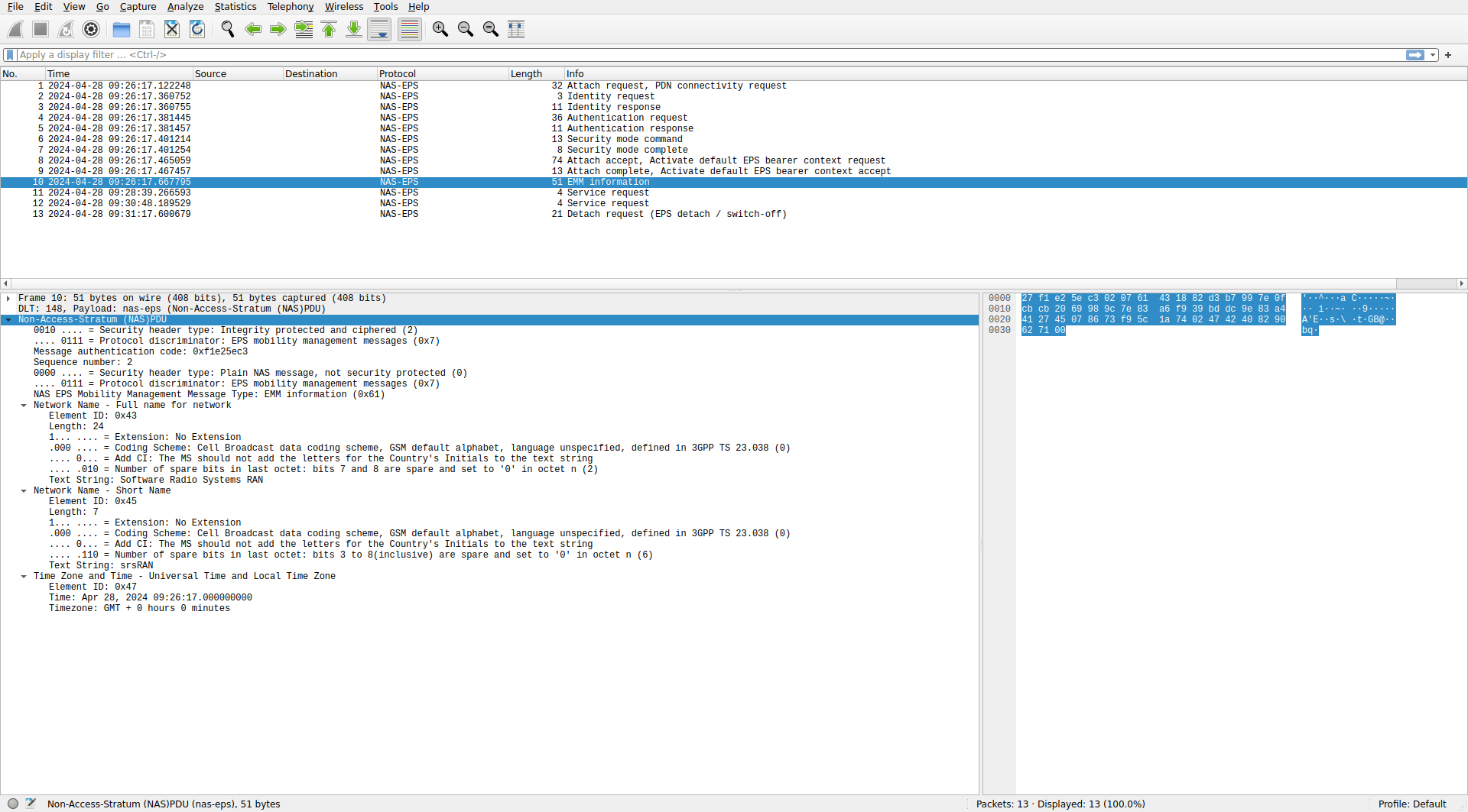
In the ue_nas.pcap capture we find that the NAS PDU is an EMM information message. It contains the name of the network and the current time and timezone. The time appears to be sent with a resolution of 1 second.
The UE replies with a MAC PDU that contains a power headroom report, a long BSR, and an SRB 2 AM ACK. With this, the network connection is complete. There are no more MAC PDUs until the pings start.
User data: ping packets
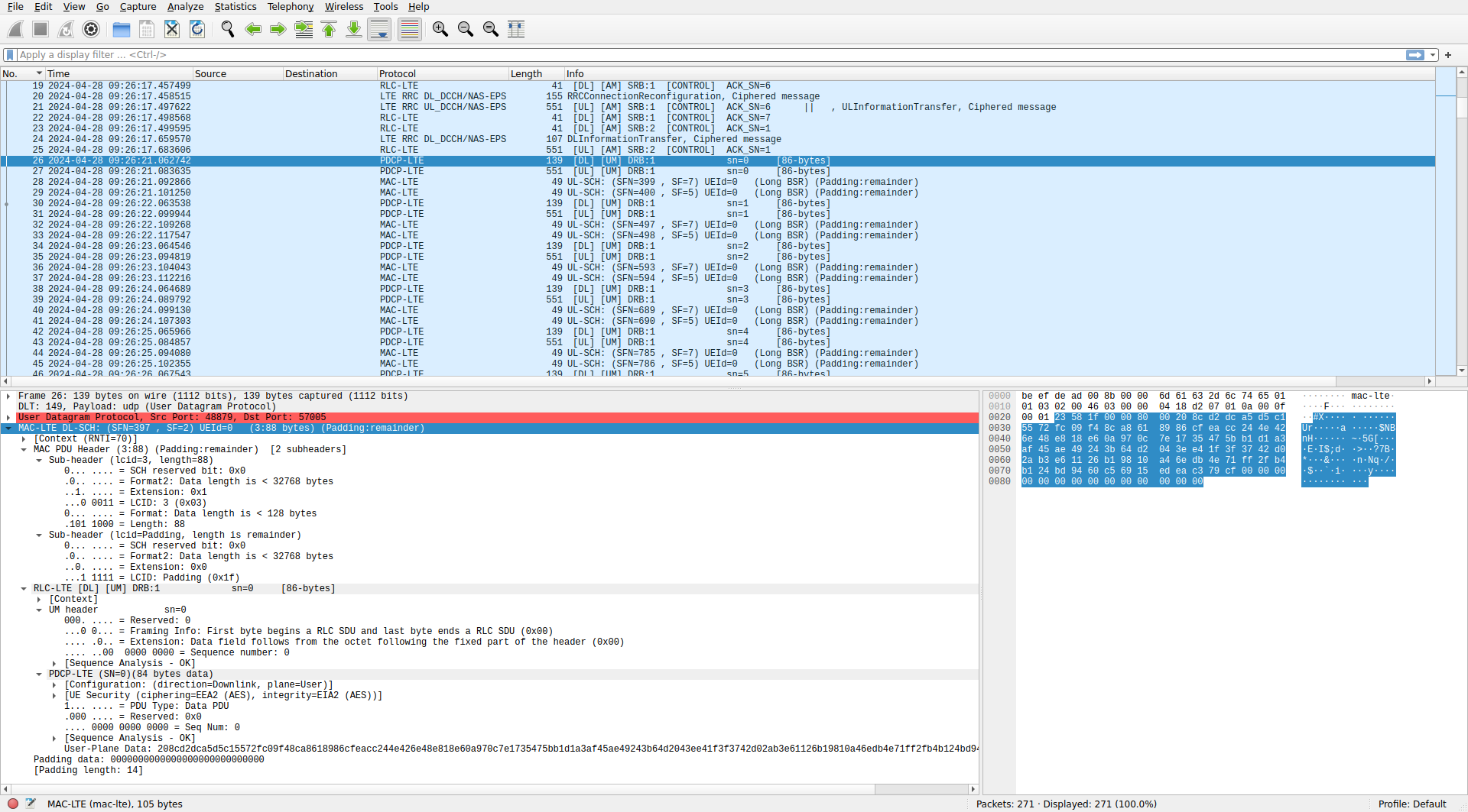
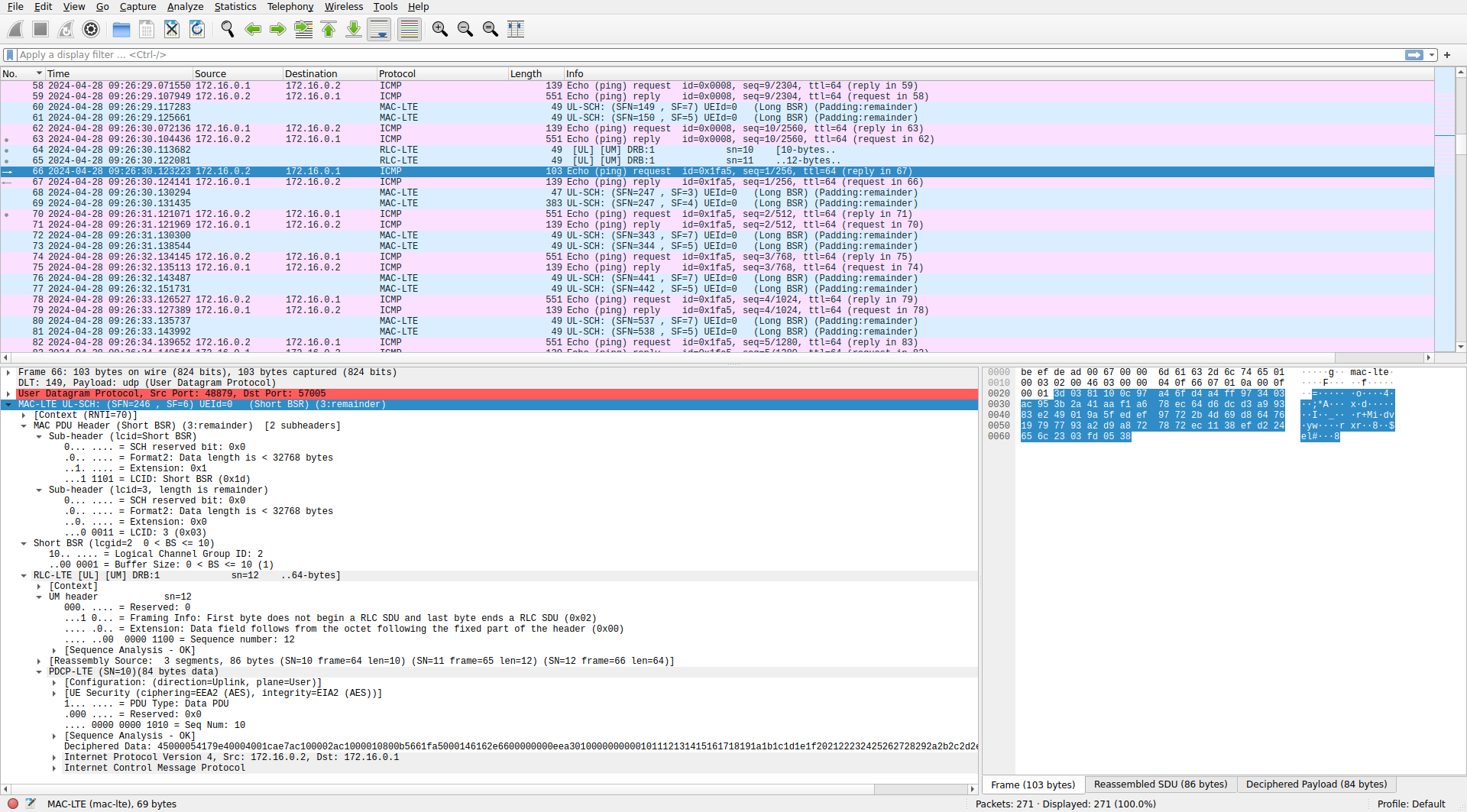
Recall that first I’m sending a ping from the EPC to the UE. This is how the MAC PDU containing the ping packet looks like. The MAC PDU contains an LCID 3 RLC UM PDU with sequence number 0 (expected, since this is the first time that DRB 1 is used). The payload of this PDU is a PDCP PDU. Wireshark knows that this is a user-plane PDU instead of a signalling PDU, since it is found in a DRB instead of an SRB. The format of the PDCP PDU differs in each case. For this user-plane PDU, we see that it is a data PDU with sequence number 0. Wireshark doesn’t attempt to dissect the payload because it is encrypted and we haven’t set the encryption key yet.
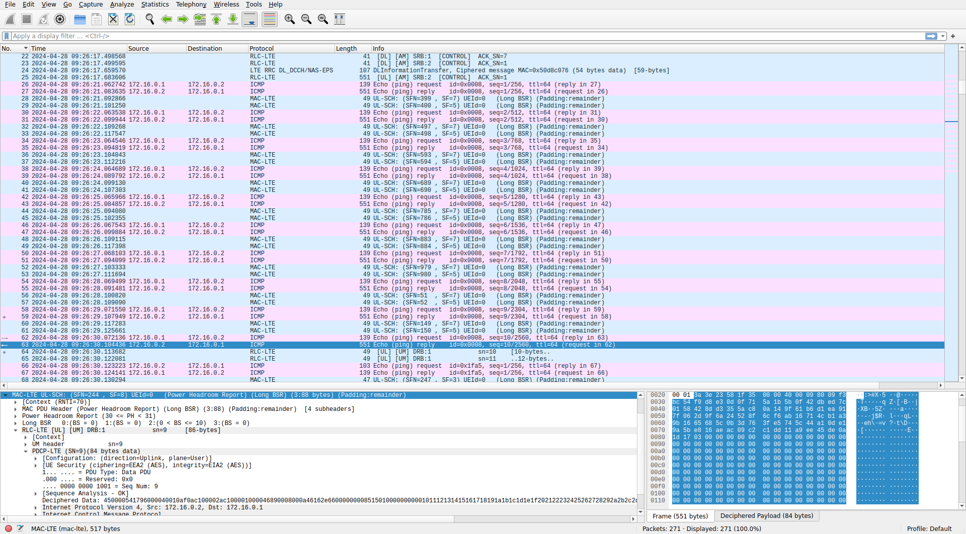
We set the UE user data encryption key in Wireshark (this key is obtained from the UE log, as we did for the RRC keys) and make sure that the PDCP protocol option “Show uncompressed User-Plane data as IP” is enabled. Now Wireshark is able to decrypt the payload of the PDCP packet and dissect it as an IPv4 packet containing an ICMP ping packet. The packet list now shows the IP addresses for the ping packet, but the Info column still shows the RLC layer information (RLC protocol, DRB and sequence number). This can be configured. In the PDCP protocol preferences we can toggle between showing the RLC info, the PDCP info (which for these packets only shows the sequence number) or the traffic info, which will show the information for the IP packet contained in the PDCP payload.
Enabling the traffic info option, we see that the sequence of 10 downlink ping packets looks as follows. The eNB sends the ping request as shown above. The UE sends a MAC PDU with power headroom and long BSR control elements and a DRB 1 RLC UM PDU that contains an encrypted PDCP PDU carrying the ping reply. Then, the UE sends two more MAC PDUs with just a long BSR control element.
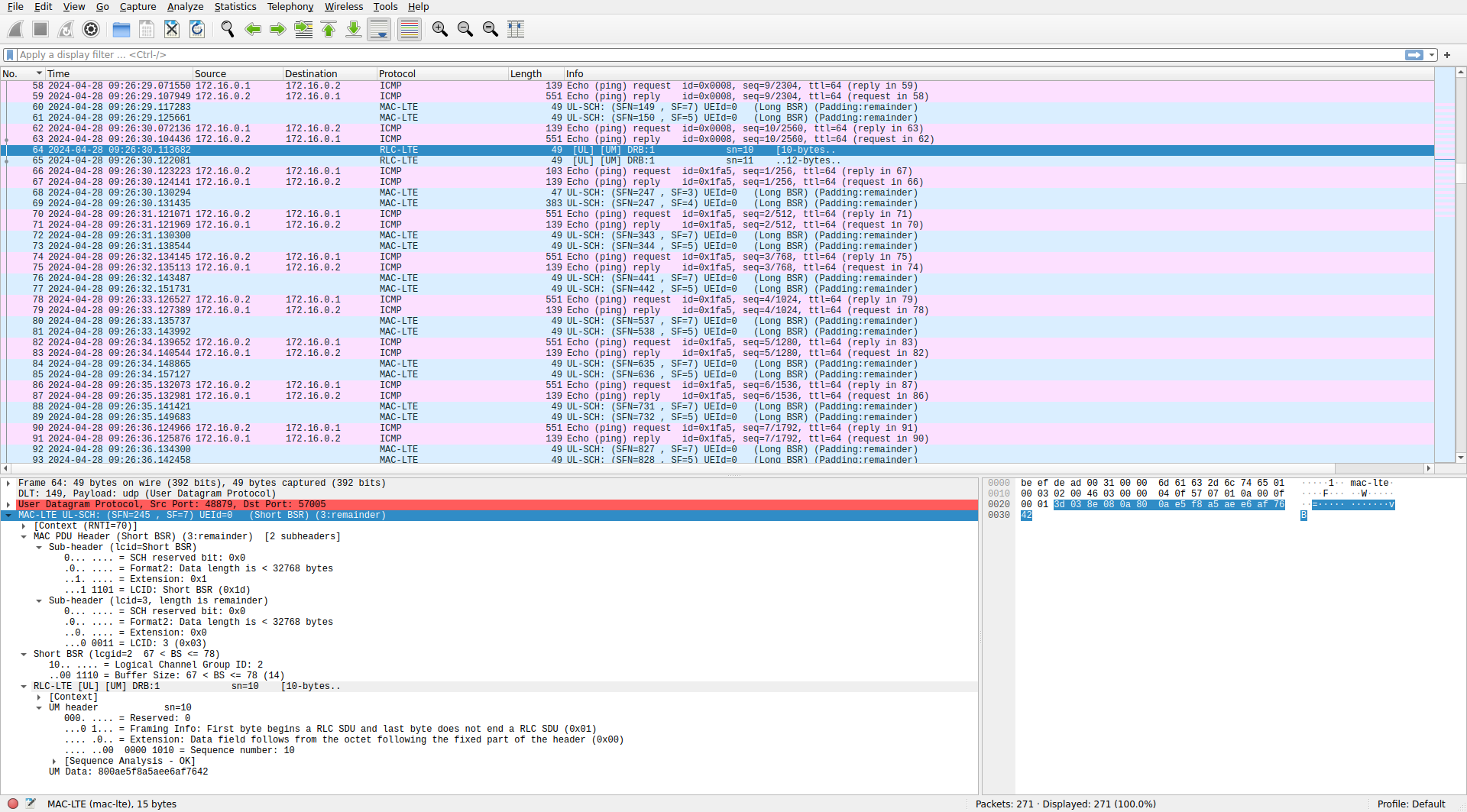
The first of the 10 uplink pings is quite interesting. For some reason the UE only gets a rather small uplink grant. It sends a MAC PDU that contains a short BSR control element stating that it still has between 68 and 78 bytes of data in its transmit buffer, and an RLC UM PDU that contains the first segment of a PDCP PDU.
The next uplink grant is still small, so the UE sends an RLC UM PDU that contains an intermediate segment of the PDCP PDU. This time, the MAC PDU doesn’t have a BSR control element.
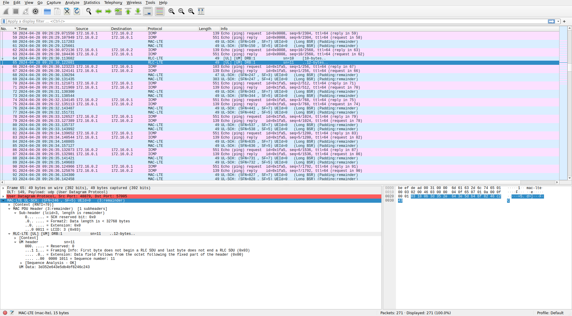
The next uplink grant is large enough and the UE is able to send a MAC PDU that contains an RLC UM PDU with the rest of the PDCP PDU. The MAC PDU also contains a short BSR control element. Wireshark is able to reassemble the PDCP PDU and dissect its payload as a ping packet.
The rest of the uplink pings don’t have anything remarkable.
Connection release
After there has been no traffic for 30 seconds, the network sets the UE to idle state by sending it an RRC connection release message. The message is a DL-DCCH message that is sent in SRB 1 using an AM PDU.
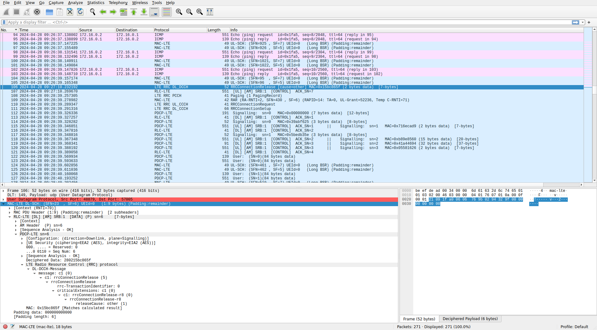
The UE replies to the connection release with an AM ACK in SRB 1. There is no acknowledge message at the RRC layer level. The UE prints the following to stdout:
Received RRC Connection Release (releaseCause: other)
RRC IDLE
Paging and reconnection
After the UE has entered the RRC idle state, a downlink ping is initiated. The network cannot send packets to the UE, because it is disconnected from the RRC. The UE is still monitoring the PCH (paging channel), so the networks sends a paging message to the UE to get it reconnected to the RRC.
The paging message is transmitted in the PDSCH with the P-RNTI (0xfffe). The transport block does not contain a MAC PDU. It directly contains a PCCH-Message ASN.1 message. In this case, the PCCH-Message contains a single paging record, which has the TMSI of the UE.
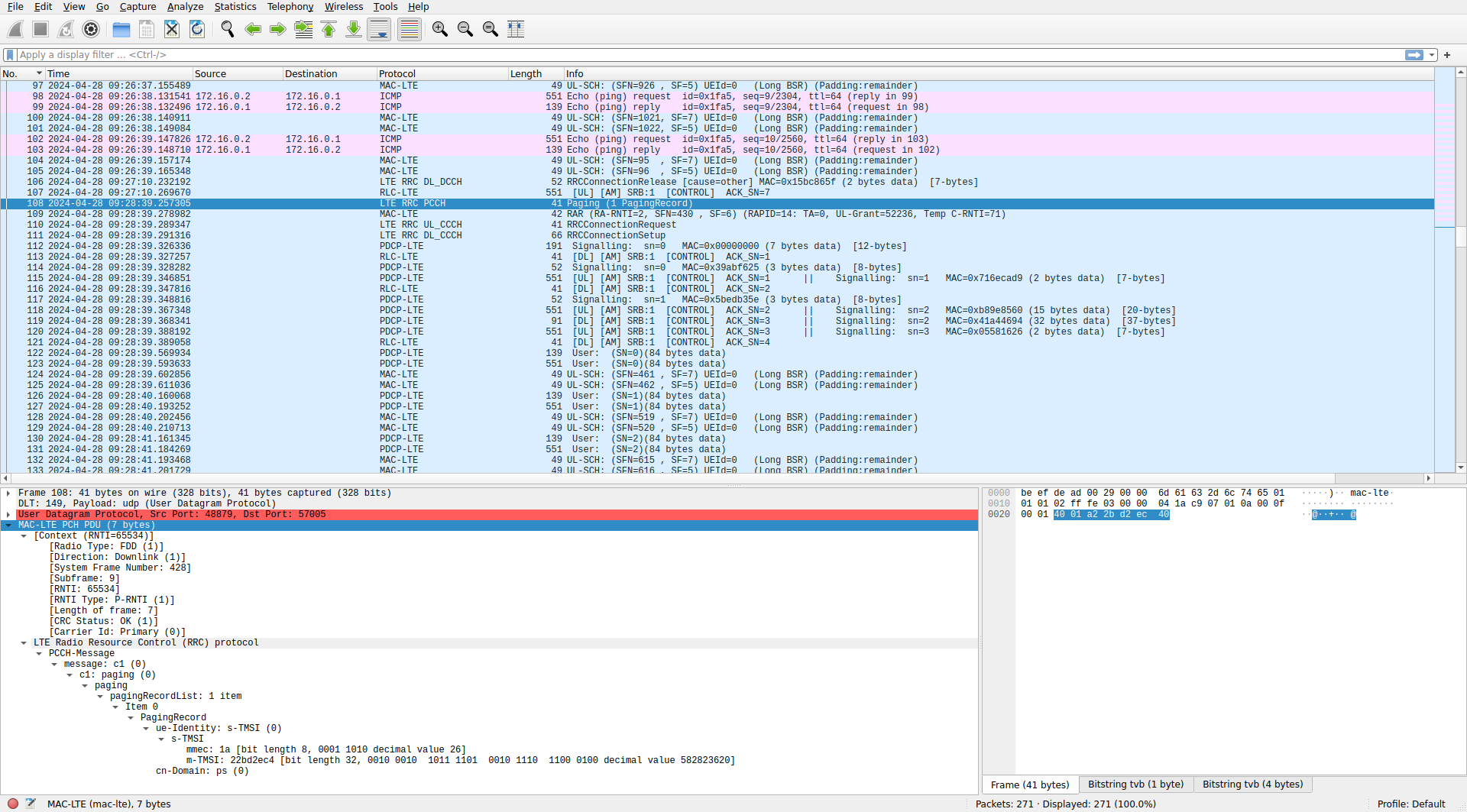
Something we can check is that the paging message has been transmitted in the appropriate radio frame according to the rule I described in my post about the PDSCH. The SIB2 in this srsRAN cell sets a default paging cycle of 32 radio frames and nB equal to oneT. Therefore, the paging message must be sent in subframe 9 of a radio frame whose SFN modulo 32 equals the UE IMSI modulo 1024 and modulo 32. This UE has the IMSI 001010123456780, which modulo 1024 and modulo 32 gives 12. The paging message is transmitted in subframe 9 of a radio frame with SFN 428. Since 428 modulo 32 also gives 12, the rule is followed. Looking at the EPC PCAP file, we can see that the EPC initiates the paging at 09:28:39.160431, but the eNB transmits the paging message at 09:28:39.257305, which is nearly 97 ms later. Since the subframes where a paging message can be sent to this UE only occur once every 320 ms, this wait is normal. It also contributes to the first ping having a very high latency:
PING 172.16.0.2 (172.16.0.2) 56(84) bytes of data.
64 bytes from 172.16.0.2: icmp_seq=1 ttl=64 time=433 ms
64 bytes from 172.16.0.2: icmp_seq=2 ttl=64 time=33.4 ms
Before sending the ping, it is necessary to wait to page the UE, and then to complete the reconnection.
After receiving the paging message, the UE initiates the reconnection by transmitting in the PRACH. This time it uses RAPID 14 and RA-RNTI 0x2.
S-TMSI match in paging message
Service Request with cause mt-Access.
Random Access Transmission: seq=14, tti=4301, ra-rnti=0x2
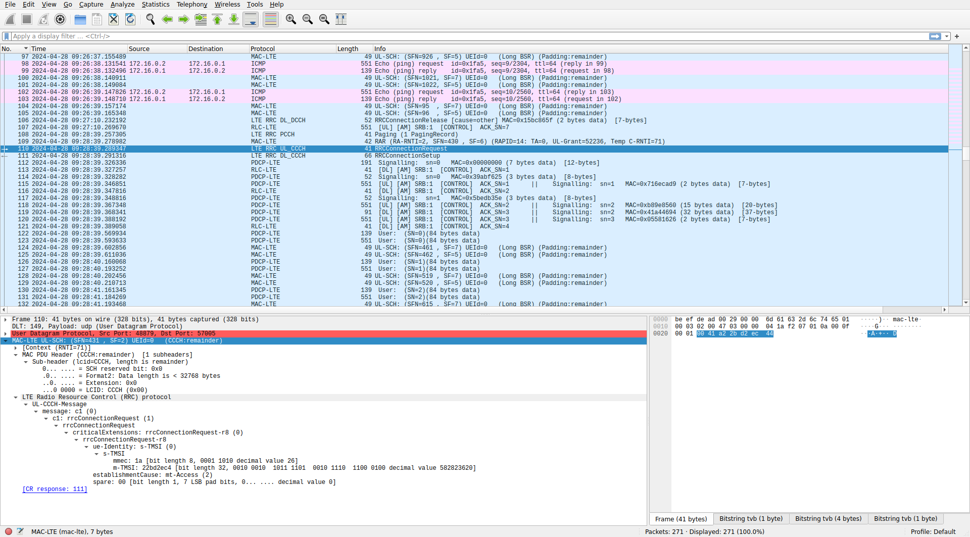
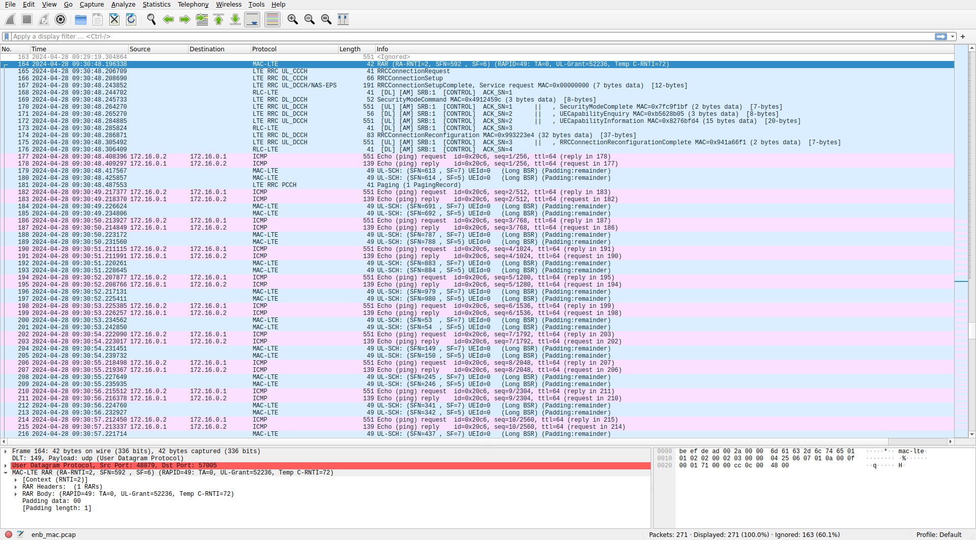
The eNB replies with a RAR as for the initial UE connection. The RAR assigns a temporary C-RNTI equal to 71 to the UE. The UE then sends an RRC connection request message over the CCCH. This is very similar to the initial RRC connection request, except that the UE now uses the TMSI 0x22bd2ec4 that it previously got from the network over an encrypted NAS connection and it indicates establishmentCause: mt-Access instead of mo-Data.
The eNB replies with a MAC PDU that contains a UE contention resolution identity control element and a CCCH SDU with an RRC connection setup message. This looks the same as during the initial connection, so I won’t show it again.
The next packet is an uplink MAC PDU. It contains power headroom report and long BSR control elements and an RLC AM PDU in SRB 1, which was just stablished in the RRC connection setup message. The sequence number of the AM PDU is zero. This is because SRB 1 was disabled when the UE disconnected from the RRC, so the sequence number starts again by zero. Wireshark is suspicious about this and flags it as a retransmission because it hasn’t understood the consequences of the RRC connection release. More importantly, the PDCP PDU contained in this AM PDU is not dissected correctly. Wireshark believes that the PDCP PDU uses EEA2 encryption and EIA2 integrity, and it mentions the configuration done in packet 14. However, this configuration is not valid anymore, because of the RRC connection release. At this point SRB 1 is again unencrypted, as in the initial UE connection.
We can also see that Wireshark is confused about how to dissect many of the following PDUs, and the ping packets do not show as IPv4 packets, but rather as PDCP user data. We need to do some manual configuration to force Wireshark to do the right thing. In the PDCP protocol preferences we enable “Ignore RRC security parameters” and make sure that “Ciphering algorithm to use if not signalled” and “Integrity algorithm to use if not signalled” are set to EEA0 (NULL) and EIA0 (NULL) respectively. This lets us dissect correctly this PDCP PDU, at the cost of not being able to see the previous ping packets and other encrypted PDCP PDUs.
The PDCP PDU is an RRC connection setup complete UL-DCCH message. It contains a NAS PDU which is a service request message. This has some cryptographic information to authenticate the UE again with the network.
The following packet is a downlink MAC PDU with an AM ACK. After this there is a downlink MAC PDU that contains an SRB 1 AM PDU with a DL-DCCH message of type security mode command. This message is enabling encryption and authentication again in SRB 1. Wireshark warns us that the message authentication code of this PDCP PDU is wrong. This is because of a subtle detail. The PDCP PDU with the security mode command uses the previous encryption setting (unencrypted), since otherwise the UE would have no way of knowing how to decrypt it. However, it uses the new integrity setting, since the UE can check the integrity of this PDCP PDU according to what the security mode command message specifies. We didn’t pay attention to this minor detail before because Wireshark was managing the settings automatically for us.
To check the integrity of this PDU correctly we need to set the PDCP protocol preference “Integrity algorithm to use if not signalled” to EIA2. With this setting Wireshark is now happy about the message authentication code.
The following packet is an uplink MAC PDU that contains a security mode complete UL-DCCH message in SRB 1. This is still unencrypted because the UE hasn’t accepted the encryption settings until it transmits this message. Integrity is done with EIA2, as for the previous message.
If we take a quick look at the packet list, we see that the next SRB 1 PDUs are being dissected as some obviously wrong messages. We need to manually set PDCP encryption to EEA2 before looking at these PDUs, since otherwise we’re just sending random data into the ASN.1 decoder for the DCCH messages.
Another thing that we need to do is to configure the new UE keys in the PDCP protocol preferences. New keys have been derived using the cryptographic parameters in the service request NAS message. We can get these keys from the UE log.
2024-04-28T09:28:39.333131 [PDCP   ] [I] Configuring security with 128-EIA2 and 128-EEA2
2024-04-28T09:28:39.333131 [PDCP   ] [D] K_rrc_enc
    0000: 8c ca cc 5c 66 b4 13 fe 60 7c 60 1f 59 06 b8 87
    0010: 6e 4e 8f 24 95 d6 a7 29 8b 97 85 19 7c 2c 2f d1
2024-04-28T09:28:39.333131 [PDCP   ] [D] K_up_enc
    0000: 40 77 6b b0 45 42 ca a1 cf eb 86 d9 1f e7 d9 2a
    0010: 54 06 e0 f9 05 e7 fe 25 ad bf 4e 98 a6 61 35 e7
2024-04-28T09:28:39.333132 [PDCP   ] [D] K_rrc_int
    0000: 22 ca 2e 6f 3d 56 98 6e f2 2d cd 60 d4 57 1b cd
    0010: 98 11 9e 28 c9 f1 de de d0 02 93 0c e7 ce e9 31
2024-04-28T09:28:39.333132 [PDCP   ] [D] K_up_int
    0000: 98 3d 81 fa ad 44 eb 43 5f f8 71 3f c0 21 d0 1c
    0010: 8c 16 e5 a7 28 8f b3 d1 29 a1 a2 e9 63 96 e8 26
However, even doing this decryption of SRB 1 doesn’t work correctly. The problem is that the encryption algorithm uses a counter called COUNT as initialization vector. The counter essentially is generated with the PDCP sequence number, but it also keeps track of sequence number overflows. It seems that the logic that Wireshark has to compute this COUNT gets confused because of PDUs with the same sequence number (due to sequence numbers resetting to zero when the UE disconnects from the RRC). In fact, if in the PDCP protocol preferences we set “Do sequence number analysis” to something other than “Only-RLC-frames”, Wireshark refuses to perform PDCP decryption.
To get around this problem we need to ignore the packets containing conflicting sequence numbers before the beginning of the reconnection. This is done by selecting them and pressing Ctrl+D (or with right click -> “Ignore”). In principle we could hand pick and ignore only the conflicting SRB 1 AM data PDUs, but it’s much simpler to ignore all the packets before the paging message (which makes sense, because encrypted PDUs use a different set of keys). Once we do this we can turn back on the automatic detection of PDCP encryption parameters and see that even the ping packets after the reconnect are dissected correctly.
The first encrypted PDU in SRB 1 is a DL-DCCH message of type UE capability enquiry. This is the same as in the initial connection. Likewise, the UE replies with a UE capability information UL-DCCH message.
After this, there is a DL-DCCH RRC connection reconfiguration similar to the one seen in the initial connection. This enables SRB 2 (although it is not used later) and DRB 1. Unlike in the initial connection, the RRC connection reconfiguration doesn’t carry a NAS message, since there is no more data to exchange with the NAS this time.
The UE replies with an RRC connection reconfiguration complete UL-DCCH message. Unlike in the initial connection, in which the UE in addition to the RRC connection reconfiguration complete also replied with a ulInformationTransfer message containing an attach complete NAS PDU, here are there are no more messages for the NAS layer.
At this point, DRB 1 is enabled and the downlink pings are transmitted as before. After the pings end, there is a period of innactivity and the network sends the RRC connection release DL-DCCH message to the UE to put it in the RRC idle state as before.
UE-initiated reconnection
The next thing that happens is that the UE starts to ping the EPC. Since the UE is disconnected from the RRC, it first needs to reconnect to the network. In this case there is no paging message, since it is the UE the one who wants to send data, not the network.
The UE transmits in the PRACH using RAPID 49 and RA-RNTI 0x2.
Random Access Transmission: seq=49, tti=5921, ra-rnti=0x2
The eNB replies with a RAR assigning temporary C-RNTI 72. Then the UE sends an RRC connection request message in the UL-CCCH. The establishmentCause is mo-Data, unlike when it responded to the paging message (in that case it used mt-Access). The following exchange of control messages is the same as when the UE reconnected after the paging message. Once the RRC connection reconfiguration message enables DRB 1, the UE can send the first ping. Due to the reconnection, this first ping has much higher latency than the rest, but not as high as when the network had to page the UE to send a downlink ping.
--- 172.16.0.2 ping statistics ---
10 packets transmitted, 10 received, 0% packet loss, time 9001ms
rtt min/avg/max/mdev = 22.400/69.443/433.421/121.427 ms
PING 172.16.0.1 (172.16.0.1) 56(84) bytes of data.
64 bytes from 172.16.0.1: icmp_seq=1 ttl=64 time=228 ms
64 bytes from 172.16.0.1: icmp_seq=2 ttl=64 time=35.6 ms
Note that in this second reconnection the UE is using new keys, so I have obtained them from the log and loaded them into Wireshark.
2024-04-28T09:30:48.251914 [PDCP   ] [D] K_rrc_enc
    0000: e9 b8 06 da 95 83 1a e4 20 c7 86 08 bc 83 15 7c
    0010: 0b 0b 51 64 ad b2 f4 68 19 19 02 cd 5c fa e8 87
2024-04-28T09:30:48.251914 [PDCP   ] [D] K_up_enc
    0000: d5 aa 71 48 2a 6a 06 07 37 f1 be bc 20 71 b6 55
    0010: 39 23 bc 75 c6 fd 9c f2 d3 39 96 ff ac cd 24 ea
2024-04-28T09:30:48.251914 [PDCP   ] [D] K_rrc_int
    0000: 79 cf 02 61 f7 16 48 24 7b fa 8f 5a 0c e8 d4 99
    0010: d0 41 df cb 8f f4 d1 a6 fa a6 8d ed 42 70 22 52
2024-04-28T09:30:48.251914 [PDCP   ] [D] K_up_int
    0000: 8a bf 15 d5 c7 3f dc af 37 20 d9 62 fe b7 6e 90
    0010: 8a 4b fb 2c f4 51 b4 2d 81 32 d3 c5 88 5a 82 a1
Something strange is that there is a paging message shortly after the first ping packet. I think the network should not send this paging message, because the UE has already reconnected. In fact this paging message doesn’t even appear in ue.pcap nor in the srsue stdout, because the UE was not monitoring the PCCH anymore.
The EPC log contains some information about this paging:
2024-04-28T09:30:48.244896 [S1AP   ] [I] Initial Context Setup Request -- E-RAB id 5
[...]
2024-04-28T09:30:48.285859 [S1AP   ] [I] Received S1AP msg. Size: 40
2024-04-28T09:30:48.285865 [S1AP   ] [I] Received Initiating PDU
[...]
2024-04-28T09:30:48.408509 [S1AP   ] [I] Preparing to Page UE -- IMSI 001010123456780
2024-04-28T09:30:48.408521 [NAS    ] [I] Starting T3413 Timer: Timeout value 2
2024-04-28T09:30:48.408585 [S1AP   ] [I] Received S1AP msg. Size: 38
2024-04-28T09:30:48.408593 [S1AP   ] [I] Received Succeseful Outcome PDU
2024-04-28T09:30:48.408594 [S1AP   ] [I] Received Initial Context Setup Response.
2024-04-28T09:30:48.408599 [S1AP   ] [I] E-RAB Context Setup. E-RAB id 5
[...]
2024-04-28T09:30:48.408652 [S1AP   ] [I] Activated EPS Bearer: Bearer id 5
2024-04-28T09:30:50.408541 [S1AP   ] [I] Timer expired
2024-04-28T09:30:50.408544 [NAS    ] [I] T3413 expired -- Could not page the ue.
This looks like a race condition. Apparently, when the eNB sends the RRC connection reconfiguration message to the UE, it also sends an S1AP message of type initial context setup response to the EPC. When receiving this message, the EPC finishes setting up the UE connection. However, the UE sends the ping packet shortly after the RRC connection reconfiguration too. This ping arrives to the EPC before the initial context setup response message. The EPC generates the ping reply (maybe it shouldn’t, since technically speaking the EPS bearer that carries this ping is not active yet) and when it tries to send the reply, it notices that the UE isn’t connected, so it tries to page the UE. The paging process finishes unsuccessfully with the expiry of the timer, since the UE never replies to the paging message.
Looking at the S1AP PCAPs, the problem seems that the latency of the initial context setup response message is too high. This message appears at 09:30:48.306450 in the eNB PCAP, but in the EPC PCAP it appears at 09:30:48.408585. The ECP sends the paging S1AP message at 09:30:48.408579, so if the initial context setup response had arrived even 1 ms earlier, the paging would have never happened.
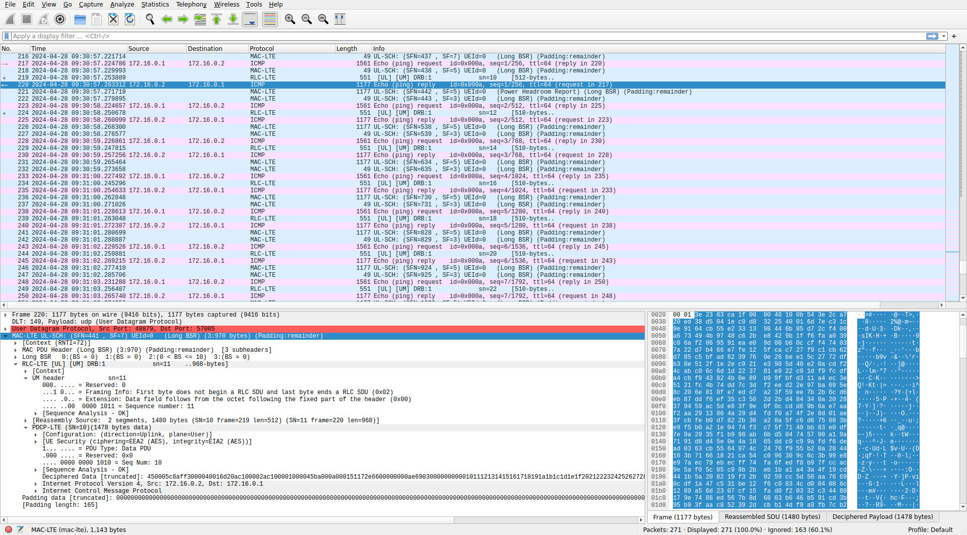
Long ping packets
After the 10 uplink pings, there are 10 downlink pings with a relatively long payload of 1450 bytes. The eNB sends the ping requests in a single transport block, so each ping goes into an unfragmented PDCP PDU as with the shorter ping packets. The UE, however, isn’t getting large enough uplink grants to send the ping replies in a single transport block. The ping replies are sent in a PDCP PDU that is fragmented into two RLC UM PDUs. These UM PDUs are sent with a time difference of 9 subframes (9 ms). This contributes to the ping latency.
UE disconnection
After all the pings were sent, I stopped srsue by pressing Ctrl+C. The application terminates in a graceful way by disconnecting the UE from the RRC. This is done by sending in SRB 2 a UL-DCCH message of type ulInformationTransfer that contains a NAS PDU. The NAS PDU is protected for integrity but not encrypted. It is a detach request message that contains the UE identity and the switch off flag.
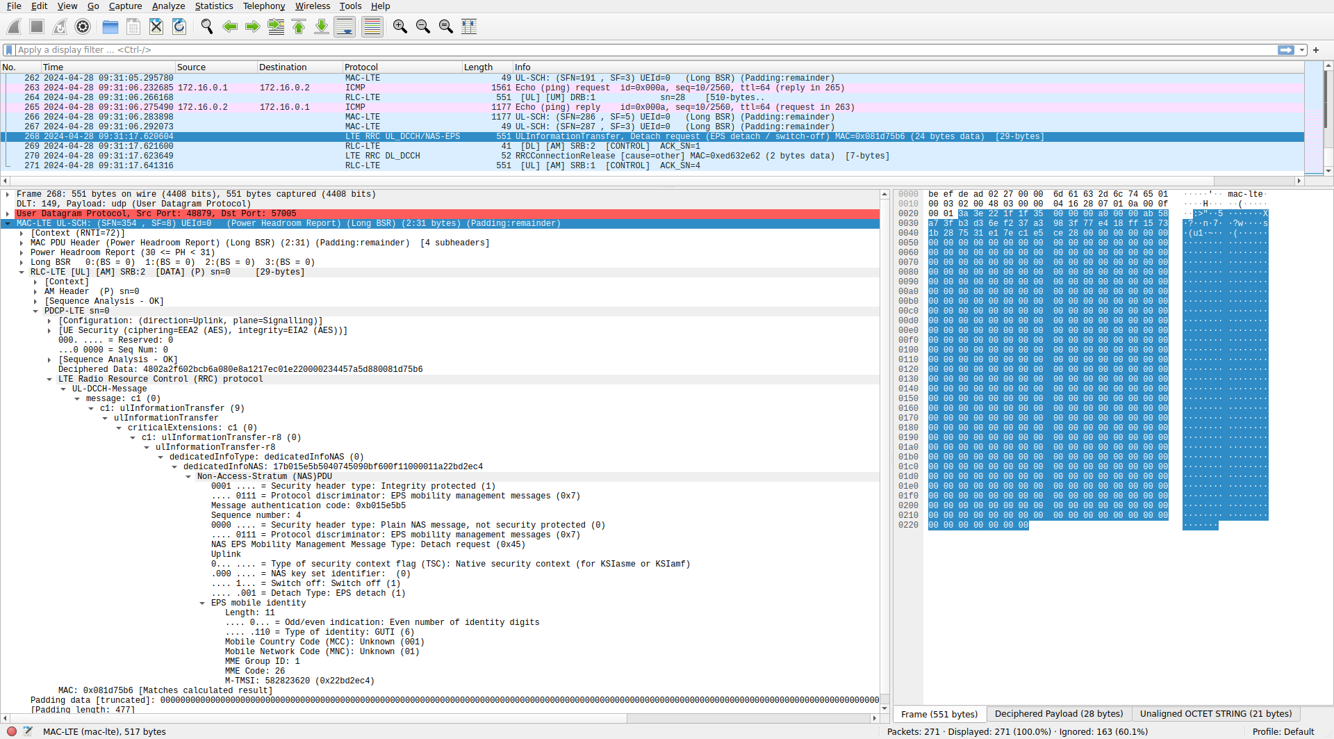
After this there is a downlink ACK in SRB 2, and then a downlink AM PDU in SRB 1 that contains a DL-DCCH message of type RRC connection release. This is identical to the connection release message that happens when the UE is sent to RRC idle because of inactivity.
UE MAC layer
The ue_mac.pcap file contains almost the same packets as enb_mac.pcap, since in this set up there is only a single UE communicating with the eNB. In addition to all the packets that we have already seen in the eNB MAC layer, the UE MAC contains packets with the MIB, SIB1, and SIB2 and SIB3. The UE decodes this information before transmitting in the PRACH to attach to the cell. The srsue application assumes that the MIB and SIBs never change, so once they have been decoded, the UE stops monitoring them, and they only appear once at the beginning of the PCAP.
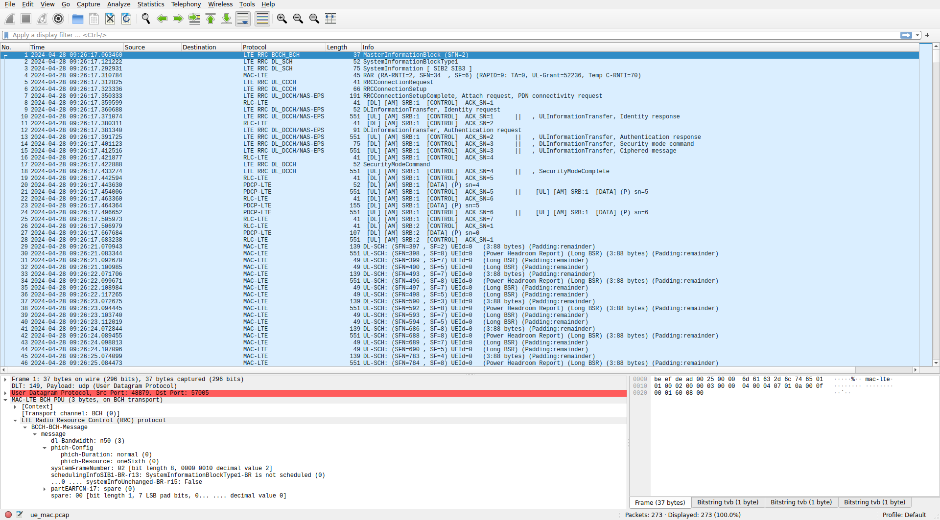
The information in the SIBs corresponds to what was configured in the example sib.conf file. This is a simplistic SIB configuration, so it is good to keep it as a reference. Here are the contents of the SIB1 as dissected in Wireshark.
systemInformationBlockType1
    cellAccessRelatedInfo
        plmn-IdentityList: 1 item
            Item 0
                PLMN-IdentityInfo
                    plmn-Identity
                        mcc: 3 items
                            Item 0
                                MCC-MNC-Digit: 0
                            Item 1
                                MCC-MNC-Digit: 0
                            Item 2
                                MCC-MNC-Digit: 1
                        mnc: 2 items
                            Item 0
                                MCC-MNC-Digit: 0
                            Item 1
                                MCC-MNC-Digit: 1
                    cellReservedForOperatorUse: notReserved (1)
        trackingAreaCode: 0007 [bit length 16, 0000 0000  0000 0111 decimal value 7]
        cellIdentity: 0019b010 [bit length 28, 4 LSB pad bits, 0000 0000  0001 1001  1011 0000  0001 .... decimal value 105217]
        cellBarred: notBarred (1)
        intraFreqReselection: allowed (0)
        .... ..0. csg-Indication: False
    cellSelectionInfo
        q-RxLevMin: -130dBm (-65)
    freqBandIndicator: 7
    schedulingInfoList: 1 item
        Item 0
            SchedulingInfo
                si-Periodicity: rf16 (1)
                sib-MappingInfo: 1 item
                    Item 0
                        SIB-Type: sibType3 (0)
    si-WindowLength: ms20 (5)
    systemInfoValueTag: 0
The SIB2 and SIB3 are sent together in the same BCCH message. These are the SIB2 contents dissected in Wireshark.
sib2
    radioResourceConfigCommon
        rach-ConfigCommon
            preambleInfo
                numberOfRA-Preambles: n52 (12)
            powerRampingParameters
                powerRampingStep: dB6 (3)
                preambleInitialReceivedTargetPower: dBm-104 (8)
            ra-SupervisionInfo
                preambleTransMax: n10 (6)
                ra-ResponseWindowSize: sf10 (7)
                mac-ContentionResolutionTimer: sf64 (7)
            maxHARQ-Msg3Tx: 4
        bcch-Config
            modificationPeriodCoeff: n16 (3)
        pcch-Config
            defaultPagingCycle: rf32 (0)
            nB: oneT (2)
        prach-Config
            rootSequenceIndex: 128
            prach-ConfigInfo
                prach-ConfigIndex: 3
                ..0. .... highSpeedFlag: False
                zeroCorrelationZoneConfig: 5
                prach-FreqOffset: 4
        pdsch-ConfigCommon
            referenceSignalPower: 0 dBm
            p-b: 0
        pusch-ConfigCommon
            pusch-ConfigBasic
                n-SB: 1
                hoppingMode: interSubFrame (0)
                pusch-HoppingOffset: 2
                .0.. .... enable64QAM: False
            ul-ReferenceSignalsPUSCH
                ..0. .... groupHoppingEnabled: False
                groupAssignmentPUSCH: 0
                0... .... sequenceHoppingEnabled: False
                cyclicShift: 0
        pucch-ConfigCommon
            deltaPUCCH-Shift: ds1 (0)
            nRB-CQI: 1
            nCS-AN: 0
            n1PUCCH-AN: 12
        soundingRS-UL-ConfigCommon: release (0)
            release: NULL
        uplinkPowerControlCommon
            p0-NominalPUSCH: -85 dBm
            alpha: al07 (4)
            p0-NominalPUCCH: -107 dBm
            deltaFList-PUCCH
                deltaF-PUCCH-Format1: deltaF0 (1)
                deltaF-PUCCH-Format1b: deltaF3 (1)
                deltaF-PUCCH-Format2: deltaF1 (2)
                deltaF-PUCCH-Format2a: deltaF2 (2)
                deltaF-PUCCH-Format2b: deltaF2 (2)
            deltaPreambleMsg3: 12dB (6)
        ul-CyclicPrefixLength: len1 (0)
    ue-TimersAndConstants
        t300: ms2000 (7)
        t301: ms100 (0)
        t310: ms200 (3)
        n310: n1 (0)
        t311: ms10000 (3)
        n311: n1 (0)
    freqInfo
        ul-CarrierFreq: 21350
        ul-Bandwidth: n50 (3)
        additionalSpectrumEmission: 1
    timeAlignmentTimerCommon: infinity (7)
And these are the contents of the SIB3:
sib3
    cellReselectionInfoCommon
        q-Hyst: dB2 (2)
    cellReselectionServingFreqInfo
        s-NonIntraSearch: 6dB (3)
        threshServingLow: 4dB (2)
        cellReselectionPriority: 6
    intraFreqCellReselectionInfo
        q-RxLevMin: -122dBm (-61)
        p-Max: 23 dBm
        s-IntraSearch: 10dB (5)
        1... .... presenceAntennaPort1: True
        neighCellConfig: No MBSFN subframes are present in all neighbour cells (1)
        t-ReselectionEUTRA: 1s
Data
All the configurations, logs and PCAP files used in this post can be found in this repository.