Lately, I have been trying to make an amplitude and phase calibration of my Hermes-Lite 2 beta2 in order to use Linrad’s smart noise blanker. This is quite a task because Linrad doesn’t support the Hermes-Lite 2 directly. Today I’ve finally managed to do it. Here I describe all my setup and calibration results.
I’m using my Hermes-Lite 2 in Linrad indirectly through GNU Radio. I use gr-hermeslite2 to receive IQ data from the Hermes-Lite and gr-linrad to stream the data to Linrad using Linrad’s RAW24 network protocol (see this post for more info). The flowgraph I’ve used is in this gist.
The problem is that in Linrad 4.12 (the latest version as of writing this), calibration doesn’t work on a network slave. There is a bug that makes Linrad hang when the calibration process starts. I wrote in Linrad’s mailing list about this and in the last few days Leif SM5BSZ has made some commits to the SVN that allow calibration on a network slave. However, I can’t make this work at 384kHz and 24bits, which is what I’m using for Hermes-Lite. Strangely, it works at lower sample rates or at 18bits. Leif has suggested that instead of calibrating using the network slave, I can make a raw recording in the network slave and then do the calibration using the recording. This is not very practical, because the pulse generator can’t be adjusted in real-time by looking at the calibration screen, but it works even in Linrad 4.12.
The next thing one has to be careful of is the level of the pulses. The Hermes-Lite 2 is a DDC transceiver with an AD9866 ADC/DAC. In front of the AD9866 there is not much: a lowpass antialias filter and an impedance transformation balun. Therefore, it is quite easy to make the ADC clip in comparison with other receivers I’ve tested, such as the FUNcube Dongle Pro+. With my homebuilt pulse generator, a lot of attenuation is required to prevent the ADC from clipping. I’m using a Minicircuits ZFDC-10-1 10dB directional coupler as an attenuator between the pulse generator and the Hermes-Lite. I also have to run the Hermes-Lite at a gain of -7dB, while I normally use a gain of 18dB.
It is not very clear how important it is that the pulses do not make the ADC clip. In principle, even if the ADC clips, the resulting waveform will still be a pulse with the required spectral properties. Leif has some words having to do with hardware linearity. Essentially, he says that it is not a problem if amplifiers saturate provided that their recovery time is fast. Most likely, the same kind of reasoning can be applied to ADC clipping. Still, I wanted to calibrate my system without ADC clipping and then test the performance with full strength pulses and the usual gain.
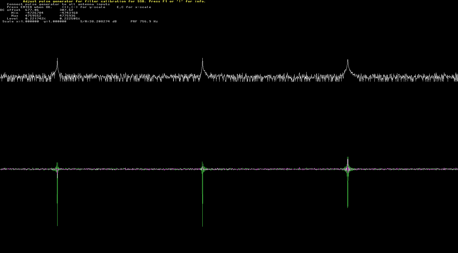
Here we can see the pulses from the generator. Those unfamiliar with Linrad’s calibration should consult my previous post and the links there. I have chosen a repetition frequency which is low but still gives enough SNR. I’m doing the calibration at a frequency of 10.2MHz.
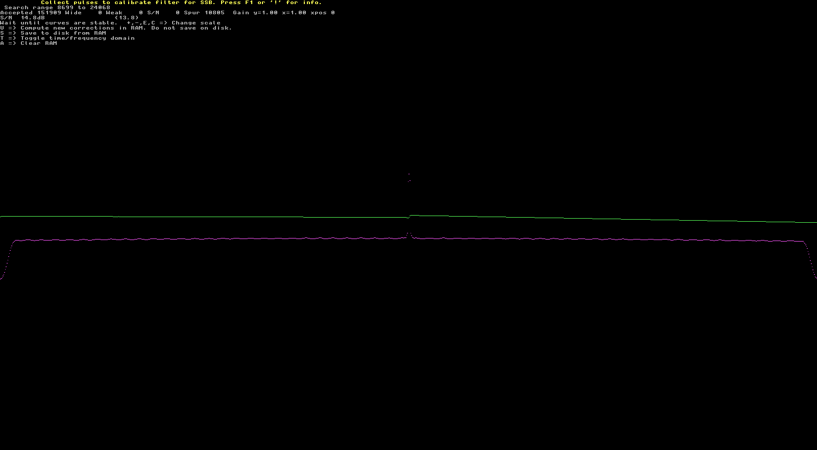
Below we see the phase and amplitude response after many pulses have been collected. It is pretty flat, except for the passband edges. This is because, at the bandwidth of interest (384kHz centered on 10.2MHz) the phase and amplitude response of the analogue components before the ADC can be assumed to be constant. The rest of the filtering is done digitally in the FPGA. The small ripples in the passband are most likely a product of the digital filter. The spike in the centre is because the pulses can’t resolve frequencies down to 0Hz. This is not a problem, because it can be fixed later by interpolating the response over the centre discontinuity.
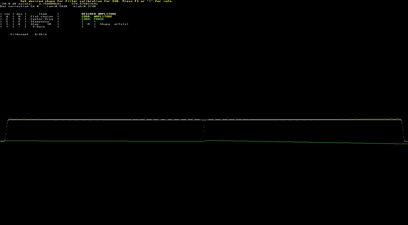
The next screenshot shows the filter shape. Since the digital filter has steep skirts, I can also set steep skirts in Linrad to match it and have good performance almost right to the passband edges.
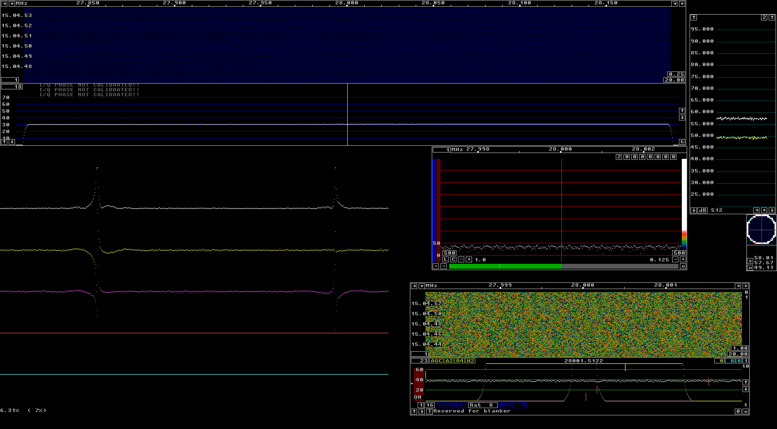
In the next two screenshots I have already removed the centre discontinuity. I’m testing how well the smart blanker works at a different frequency from the frequency of calibration. In this case, I’m using 28MHz. The first screenshot shows the pulses without the blanker and the second shows the pulses almost completely removed by the blanker. Their remains can be removed by the dumb blanker.

I have also tested the smart blanker with no attenuation between the pulse generator and the Hermes-Lite, and a gain of 18dB as usual. It still works fine. I have also tested by adding the pulses onto the RF signals from my dipole antenna and the blanker works well.
Update 14/04/2017: The pulse generator should not be connected directly to the Hermes-Lite. The amplitude of the pulses is around 4.6V into 50 Ohms and this exceeds the maximum voltage at the RF inputs of the AD9866. It seems I have damaged my AD9866 by doing this (although it only started failing 48 hours later). Always check that the level of the pulses is OK for your hardware. For the Hermes-Lite 2.0 beta2, the maximum peak voltage allowed at the RF input is around 1V.
Judging by how flat the phase and amplitude response of the Hermes-Lite is, I’m wondering if one could do without the calibration and assume an ideal response (except possibly at the passband edges). I’m also wondering if, as I think, the deviation from the ideal response comes from the digital filters, whether the same calibration data could be used for all Hermes-Lite units, and, more interestingly, whether this calibration data could be derived theoretically instead of experimentally just by looking at the digital filter coefficients.