Lately, I’ve being talking with Juan Antonio EA4CYQ and Pedro EA4ADJ about performing Linrad calibration to enable the use of the smart noise blanker. They pointed me to the SIGP-1 by Alex HB9DRI, which is a 144MHz pulse generator with which I was already familiar, and a simpler pulse generator by Leif SM5BSZ which I hadn’t seen before.
Leif’s generator is very simple. It uses a 555 timer to generate a square wave, a 74AC74 flip-flop to divide the frequency of the square wave by 2 and obtain a precise 50% duty cycle, a 74AC04 inverter as a driver, and capacitive coupling to turn the edges of the square wave into RF pulses. Alex’s SIGP-1 is an improvement over Leif’s design. It generates the square wave in the same manner, but then it uses a helical bandpass filter for 144MHz with around 5MHz bandwidth to convert the square wave into 144MHz pulses, and a PGA-103+ MMIC RF amplifier and a BFR91 RF NPN transistor as a class A amplifier to increase the output level. The SIGP-1 has two main advantages over Leif design. The output is stronger, so the S/N of the pulses is higher, and the filtering helps prevent saturation in the receiver. However, Leif’s design uses only simple components and it’s adequate in many cases.
I have built and tested Leif’s generator and used it to calibrate my FUNcube Dongle Pro+ at 144MHz. I’ve also tried doing the calibration at other frequencies and it also works well, but the pulses are not very strong at 432MHz and above.
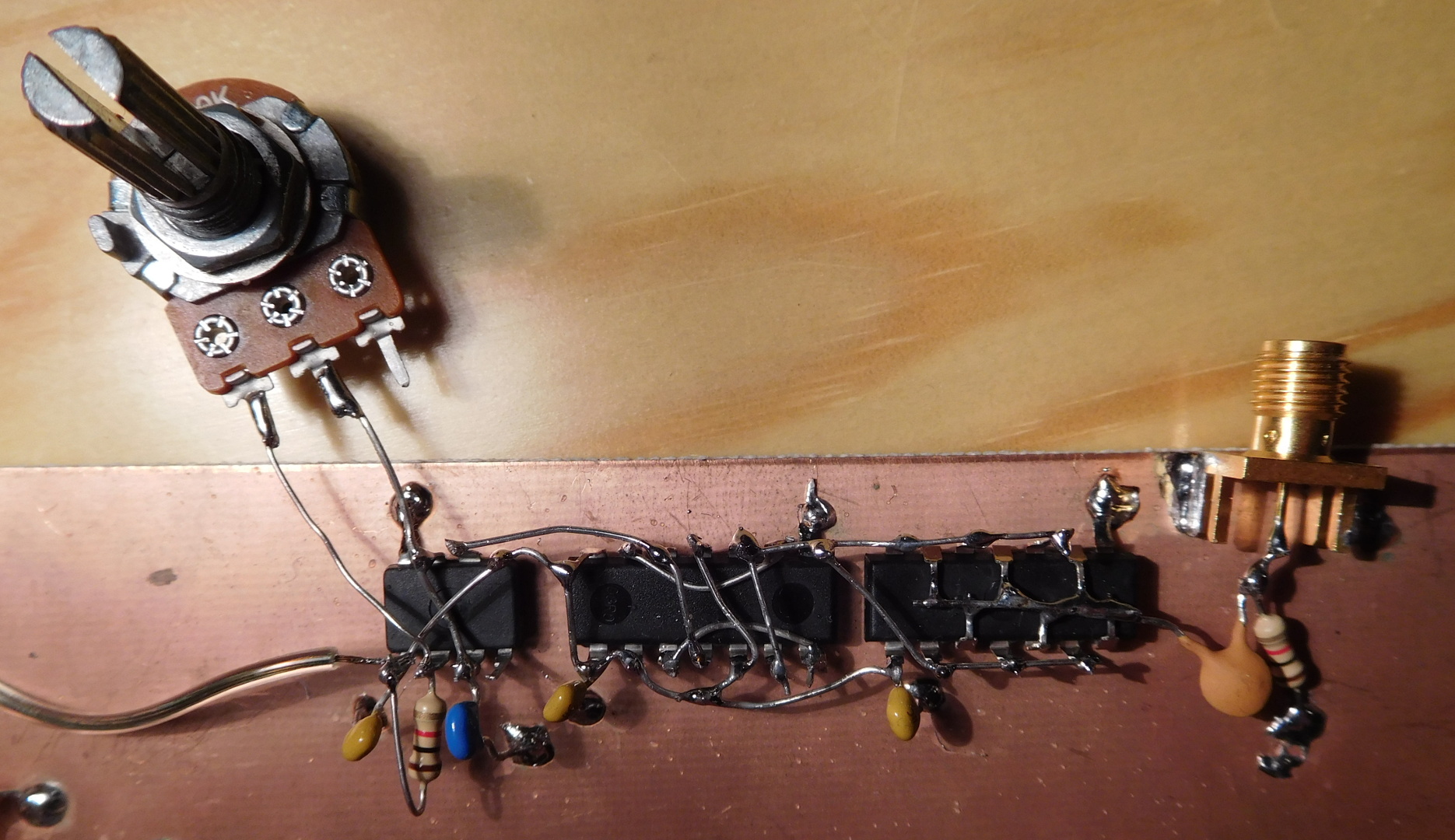
I have built the pulse generator using dead bug style on a piece of scrap PCB using mostly junk-box components. Instead of the 10k potentiometer and 1k resistor I used a 100k potentiometer, 220uF and 220pF capacitors instead of 330uF and 270pF, and a 74ACT04 instead of the AC, since my local electronics store didn’t have the AC in stock. The AC should perform slightly better than the ACT, because it has a bit less propagation delay and symmetric thresholds for the input voltage. The difference is minor, however. I’ve used a 100uF capacitor as power supply decoupling on every IC.
Below you can see on the oscilloscope several waveforms produced by the pulse generator. The first shows the 555 timer and 74AC74 flip-flops producing the square wave. The duty cycle of the 555 is different from 50% in this case, but this is unimportant.

The next capture shows that the rise time of the 74AC04 is much faster in comparison with the 555. The ringing is probably due to inadequate probing (I was using the ground clip lead).

Next we show the RF pulse produced after the output capacitor.

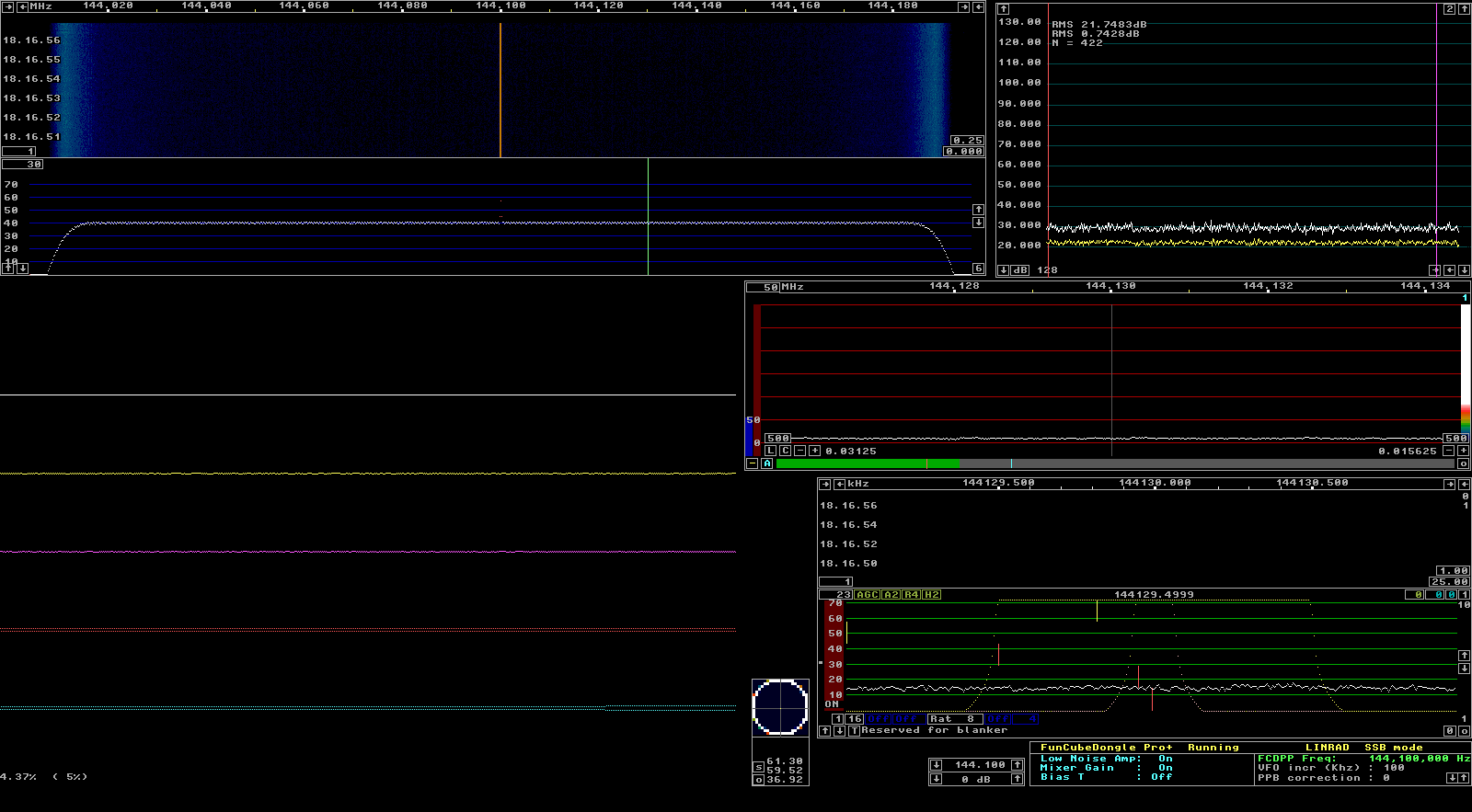
The complete procedure of calibrating Linrad using a pulse generator is outside the scope of this post. Alex HB9DRI has a nice video tutorial, and there is also a lot of information in some of Leif’s Youtube videos. Here I’ll just show the relevant screenshots of Linrad.
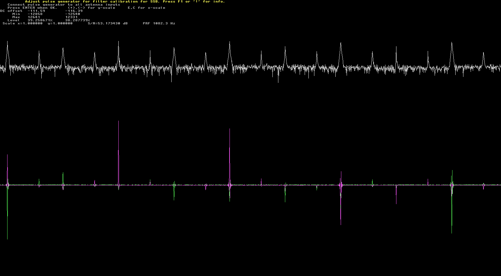
The FUNcube dongle has been tuned to 144.100MHz and the LNA is on. The first calibration screen shows the pulses. The pulse repetition frequency given by Linrad is 104.5Hz, while it is really 209Hz. For some reason, every other pulse is weaker, and Linrad only tracks the strongest pulses. This can’t be seen in the screenshot below, since the next pulse is already off screen (another screenshot below shows this effect properly). The very weak pulse in the screenshot below is the 555 changing from high to low. This gets coupled somehow into the RF output (probably due to insufficient decoupling). The pulse is very weak, so this is not a problem. The effect that every other pulse is weaker only appears in the 144MHz band. It doesn’t happen in HF or 432MHz. I think it might be caused by the 144MHz SAW filter in the FUNcube dongle. The weaker pulses are rejected by the calibration process. This is more or less the slowest pulse repetition rate I could set while getting enough S/N for calibration. It is best to use a pulse repetition rate as low as possible to get better resolution in the frequency domain.

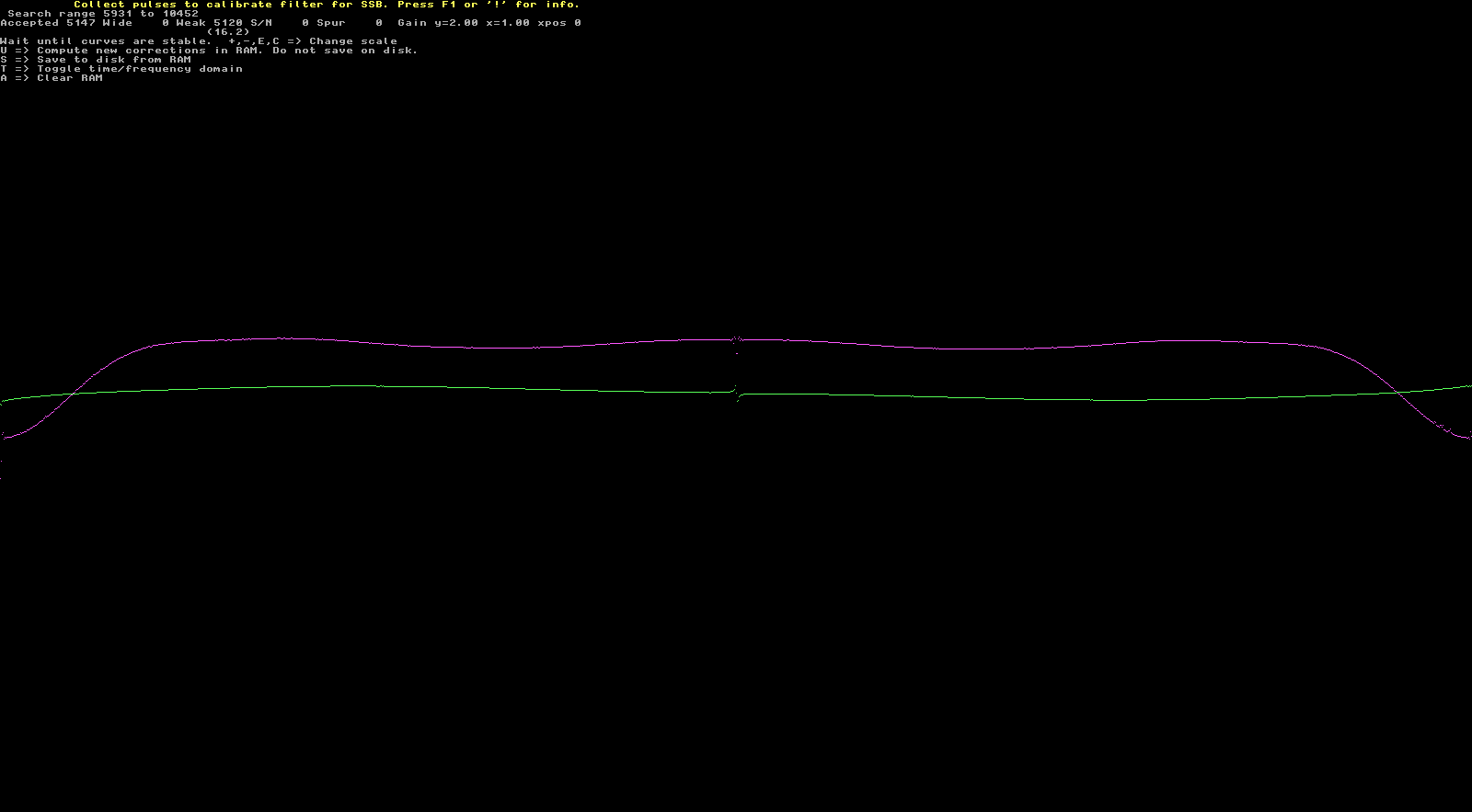
The second calibration screen shows Linrad accepting half of the pulses (the strong ones) and rejecting the weaker ones. The frequency and phase response is built up as pulses get accepted.
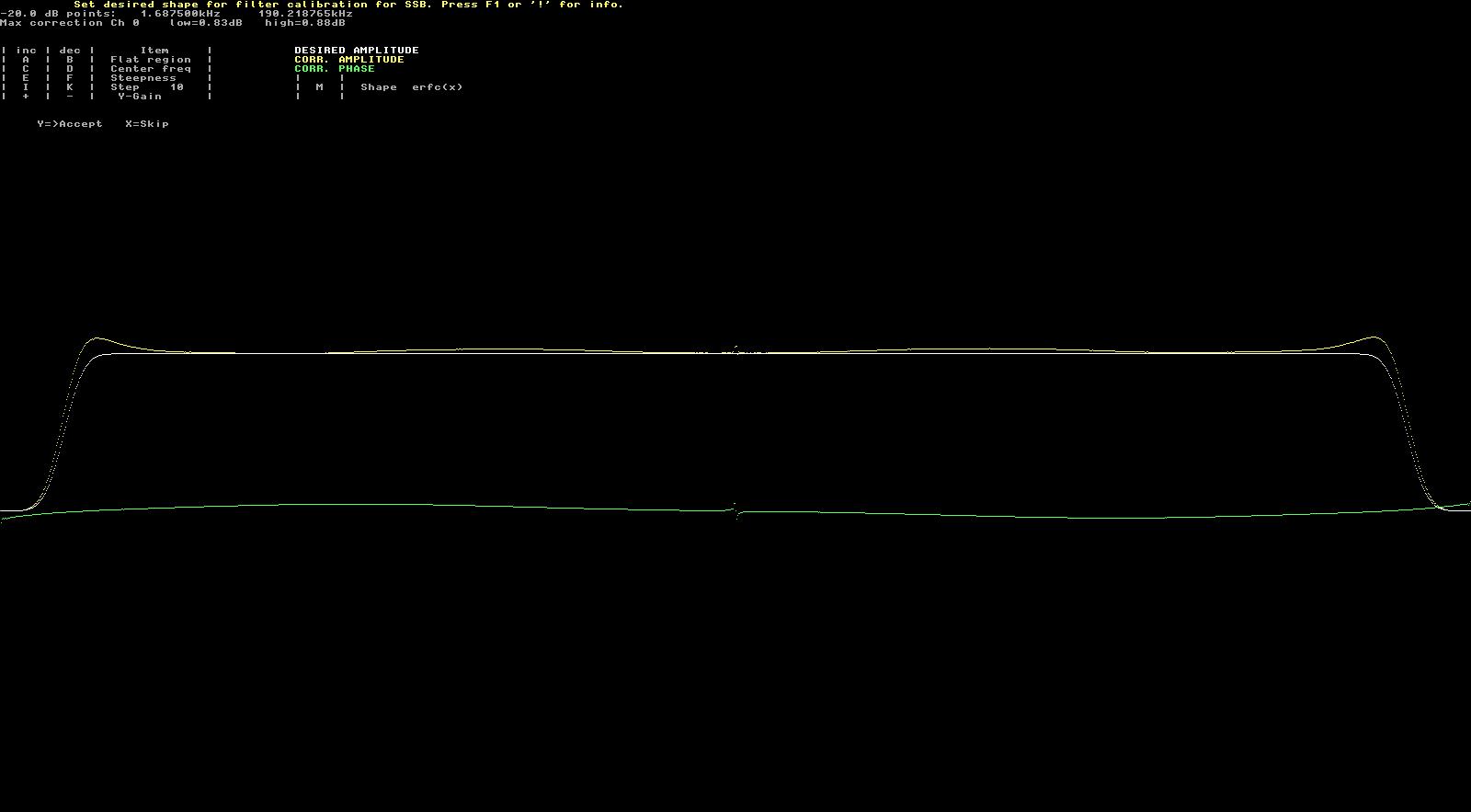
In the third calibration screen I accept the default shape for the filter.
Next, I set a much faster pulse repetition rate to test the noise blanker. This produces stronger interference in the receiver, so the effects of the blanker are much more noticeable. Here we can see the pulses of three different sizes. The weakest pulses correspond to the 555. The other pulses are the edges of the square wave output of the 74AC04. For some reason, rising edges generate stronger pulses into the receiver than falling edges (or vice versa).
Below we see the pulses in Linrad’s oscilloscope and the strength of the interference in the waterfall and S-meter. The smart noise blanker is disabled.

Finally, we enable the noise blanker and we see that the pulses are cancelled very well.
One comment