This post is a continuation of my series about the 5G NR RAN. In these posts, I’m analyzing a recording of the downlink of an srsRAN gNB in a Jupyter notebook written from scratch. In this post I will show how to decode the PBCH (physical broadcast channel). The PBCH contains the MIB (master information block). It is transmitted in the SSB (synchronization signals / PBCH block). After detecting and measuring the synchronization signals, a UE must decode the PBCH to obtain the MIB, which contains some parameters which are essential to decode other physical downlink channels, including the PDSCH (physical downlink shared channel), which transmits the SIBs (system information blocks).
In my first post in the series, I already demodulated the PBCH. Therefore, in this post I will continue from there and show how to decode the MIB from the PBCH symbols. First I will give a summary of the encoding process. Decoding involves undoing each of these steps. Then I will show in detail how the decoding procedure works.
PBCH encoding
The PBCH is formed around a 24-bit ASN.1 UPER message that contains the MIB. The ASN.1 message is the BCCH-BCH-Message defined in Section 6.2.1 in TS 38.331. To this 24-bit message, 8 additional bits are added to conform the PBCH payload, as described in Section 7.1.1 of TS 38.212. These 8 additional bits contain time and frequency information about the location of the PBCH transmission. More in detail, they are:
- The 4th, 3rd, 2nd and 1st LSBs of the SFN (the remaining 6 MSBs of the 10-bit SFN are included in the MIB).
- The half frame bit (which specifies in which half of the radio frame this SSB is transmitted).
- The meaning of the remaining 3 bits depends on the value of the \(\overline{L}_{\mathrm{max}}\) parameter, which gives the number of candidate SSBs in a half frame. This parameter is defined in Section 4.1 in TS 38.213, and it depends on the frequency band and whether shared spectrum channel access is used. In this case, the recording is below 3 GHz and without shared spectrum channel access, so \(\overline{L}_{\mathrm{max}} = 4\). For values of \(\overline{L}_{\mathrm{max}}\) other than 10, 20 and 64, the first of these 3 bits is the MSB of the \(k_{\mathrm{SSB}}\) parameter, which gives the number of subcarriers between the lowest subcarrier of the SSB and the lowest subcarrier of the CORESET0, where the PDCCH for the SIB is transmitted. The two remaining bits are reserved in this case.
The 32-bit payload is now interleaved. The interleaving algorithm is also defined in Section 7.1.1, but the text there is somewhat confusing, because it mentions the condition “if \(\overline{a}_i\) is an SFN bit”, without clarifying that this applies both to the 4 LSBs of the SFN that have been added as well as to the 6 MSBs of the SFN that are present inside the MIB. A better way of explaining this algorithm is as follows. First form a sequence \(a’_0, a’_1, \ldots, a’_{31}\) in the following way. The first 10 bits are the SFN, where the 6 first of these 10 bits are extracted from bits 1 through 7 in the MIB (counting the first bit as 0), and the remaining 4 bits are the 4 LSBs that have been added. The next bit is the half frame bit. The next three bits are the 3 final bits that have been added. The remaining bits are the rest of the MIB, maintaining their relative order. Finally interleave this sequence according to \(a_{G(j)} = a’_j\), \(j = 0, 1, \ldots, 31\), where the permutation \(G\) is given in the TS.
The interleaved 32-bit payload is then scrambled, except for a few of the 8 additional bits, which are not scrambled. The bits that are not scrambled bits are the 3rd and 2nd LSBs of the SFN (system frame number), the half frame bit, and any bit belonging to the candidate SSB index (in the case where \(\overline{L}_{\mathrm{max}}\) is different from 10, 20, 64, there are none of these bits).
Denote by \(M\) the number of bits which are scrambled. In this case, \(M = 29\), since only 3 bits are not scrambled. A pseudorandom scrambling sequence \(c\) of \(4M\) bits is generated using the physical cell ID \(N_{\mathrm{ID}}^{\mathrm{cell}}\) as initialization value. Denote by \(\nu \in \{0, 1, 2, 3\}\) the 2-bit number formed by the 3rd and 2nd LSBs of the SFN. The subsequence \(c(\nu M), c(\nu M + 1), \ldots, c(\nu M + M -1)\) is selected and used to scramble the \(M\) bits that need to be scrambled.
A 24-bit CRC is appended to the scrambled 32-bit payload. The CRC is computed using the CRC24C polynomial given in Section 5.1 in TS 38.212. The resulting 48-bit message is coded using Polar coding to obtain an 864-bit message. This process is divided into the following steps.
First, the 48 bits are interleaved as described in Section 5.3.1.1 in TS 38.212. This interleaver is specially designed to leave most of the CRC bits at the end of the message, as that can be useful for the Polar decoder. The interleaver works in the following way. An interleaver permutation \(\Pi_{\mathrm{IL}}^{\mathrm{max}}\) is defined for a message length of 164 bits, which is the maximum message length that possibly needs to be interleaved (this maximum length is only used with the PDCCH, not with the PBCH). To obtain a permutation \(\Pi\) for a shorter message length of \(K\) bits, the permutation \(\Pi\) is defined by setting \(\Pi(m) = \Pi_{\mathrm{IL}}^{\mathrm{max}}(j_m) – (164 – K)\), for \(m = 0, 1, \ldots, K – 1\), where \(0 \leq j_0 < j_1 < \cdots < j_{K-1} < 164\) are all the indices \(j\) such that \(\Pi_{\mathrm{IL}}^{\mathrm{max}}(j) \geq 164 – K\). The permuted message is \(c_k’ = c_{\Pi(k)}\) for \(k = 0, 1, \ldots, K-1\). An intuitive way to think about this permutation is that \(164 – K\) virtual bits are prepended to the message, then the permutation \(\Pi_{\mathrm{IL}}^{\mathrm{max}}\) is applied, and finally the virtual bits are removed, leaving the rest of the bits in the same relative order.
Then the 48 interleaved bits are encoded with a Polar code to yield 512 bits. This is described in more generality in Section 5.3.1.2 in TS 38.212. The case of the PBCH is particularly simple because it does not use parity check bits. A 512-bit vector \(u\) is formed in the so-called subchannel allocation process in the following way. Table 5.3.1.2-1 in TS 38.212 gives the 1024 elements of a 1024-element Polar code (the maximum size used by NR) in increasing order of reliability. To form a smaller Polar code, such as a 512-bit code, only the elements with indices smaller than 512 are taken, in the same relative order. From this, the 48 elements with largest reliability are selected to encode the message. The 48-bit interleaved message is placed in the components of \(u\) corresponding to these elements, in increasing order of component index (not in increasing order of reliability). All the remaining components of \(u\) constitute the set of frozen bits and are set to zero.
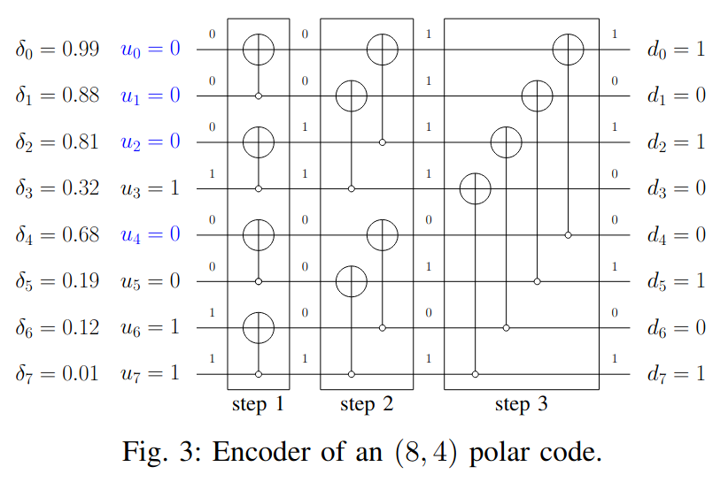
The Polar codeword is formed as \(d = u G_N\), where \(G_N = (G_2)^{\otimes n}\) is the \(n\)-th Kronecker power of the matrix\[G_2 = \begin{pmatrix}1 & 0\\ 1 & 1\end{pmatrix}.\]Here \(N\) is the length of the Polar code, which must be a power of 2 (for the PBCH, \(N = 512\)) and \(n\) is defined by \(2^n = N\). A good way to understand this encoding process is by means of the following diagram, which is shown for \(N = 8\). The set of frozen bits is marked in blue, and the message is allocated to components 3, 5, 6, 7 in \(u\).
The next step is sub-block interleaving, defined in Section 5.4.1.1 in TS 38.212. The 512-bit Polar codeword is divided into 32 sub-blocks of 16 consecutive bits each. These sub-blocks are permuted by considering each block as an indivisible unit. The 32-element permutation is given in a table in the TS.
Finally, a rate-matching algorithm is used to generate 864 bits from these 512 bits. The rate-matching algorithm is more general and supports repetition, puncturing and shortening using a circular buffer. For the PBCH, the particular use of this rate-matching algorithm is very simple. The first 512 bits of the output are the 512 input bits, and the remaining 352 output bits are a repetition of the first 352 output bits.
These 864 bits are scrambled, and mapped using QPSK modulation to the 432 resource elements allocated to the PBCH data in the SSB. The scrambling is done as follows. For \(\overline{L}_{\mathrm{max}} = 4\), a pseudorandom sequence \(c\) of length 4×864 is generated using \(N_{\mathrm{cell}}^{\mathrm{ID}}\) as initialization value. An 864-bit subsequence \(c(\nu864), c(\nu864 + 1), \ldots, c(\nu864 + 863)\) is chosen as the scrambling sequence depending on the value of \(\nu\), which is given by the two LSBs of the SSB index. In the case \(\overline{L}_{\mathrm{max}} > 4\), the sequence has length 8×864 instead and \(\nu\) is defined by the 3 LSBs of the SSB index.
Preparations for Polar decoding
The first steps for decoding the PBCH consist in undoing everything that happens after Polar encoding in order to obtain LLRs (log-likelihood ratios) for the 512-bit Polar codeword. In my first post in the series, I had already demodulated the QPSK symbols in the PBCH. Here I show the constellation plots again for reference.

In this recording, the 5G NR downlink signal is fairly simple, since it is an srsRAN 5 MHz cell with the default configuration. The SSB is transmitted only once in each radio frame. Therefore, the SSB index is always \(\nu = 0\), and all the PBCH blocks can be descrambled with the same sequence, which is obtained by calculating a pseudorandom sequence of length 864 with the initialization value \(N_{\mathrm{cell}}^{\mathrm{ID}}\). After descrambling, the symbols are converted to LLRs with the formula\[\frac{2}{\sqrt{2}\sigma^2}y,\]where \(y\) is the amplitude of the soft symbol and \(\sigma\) is the variance of the real (or imaginary) part of the noise. Here the factor \(1/\sqrt{2}\) appears because the nominal amplitude of the constellation symbols is \(1/\sqrt{2}\).
In this recording the SNR is very high. By taking the absolute value of the symbols and computing the standard deviation, I have estimated \(\sigma = 0.03\). Therefore, the resulting LLRs are quite large.
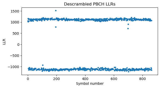
The next step is to undo the rate-matching by soft-combining the repeated symbols. Recall that the first 352 symbols are repeated at the end. Therefore, we add the last 352 symbols to the first 352 symbols, reducing the codeword size to 512 symbols. We can see in the LLR plot that the amplitude of the first symbols has doubled after soft-combining.
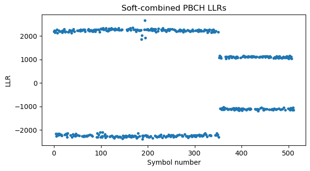
Next we undo the sub-block interleaving. It is difficult to appreciate the effect of this in the LLRs plot because only one of the sub-blocks of smaller amplitude gets moved to the zone with larger amplitude.
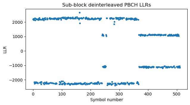
It is easier to visualize why this happens with the help of the following graphical representation of the sub-block interleaver permutation. The repeated symbols (which have twice as much LLR amplitude) occupy the first 22 sub-blocks (because each sub-block has 512/32 = 16 symbols). Therefore, looking at \(y\) in the figure below, we see that sub-block 15 belongs to the non-repeated region (so it has small LLR amplitude) and gets deinterleaved to the middle of the large LLR region, and sub-block 22, which belongs to the repeated region (so it has large LLR amplitude) gets moved one position to the right. All the remaining elements stay in the same region (either the large LLR amplitude region or the small LLR amplitude region).

The 512 LLRs that we obtain after sub-block deinterleaving correspond to the encoded Polar codeword.
Polar decoding
I didn’t have any previous experience with Polar coding, and in fact I have been learning how it works while preparing this post. This has both a good side and a bad side. The good side is that I’ll be starting from scratch and will link the resources I’ve used to learn, so the post could be useful for people interested to learn about Polar coding using 5G as a practical example. The bad side is that I might miss to give more context or insight, which is something that a more experienced person could do.
Polar codes were introduced in 2007 by Arıkan in the paper Channel polarization: A method for constructing capacity-achieving codes for symmetric binary-input memoryless channels. Since they are relatively recent, Polar codes are a highly active area of research. There are very recent papers about improved methods to decode Polar codes, and 3GPP doesn’t recommend any particular approach (in stark contrast with CCSDS, which always describes a reference implementation in their green book and link useful sources). Here I will implement a basic SC (successive cancellation) decoder based on LLRs, rather than the more advanced SCL (successive cancellation list) decoder, which gives better results. Nevertheless, the SC decoder is still useful in practical applications. For instance, srsRAN implements an SSC (simplified successive cancellation) decoder, probably based on the paper A Simplified Successive-Cancellation Decoder for Polar Codes, to which I will be referring for some of the formulas.
One of the first resources I read to learn how Polar codes work was this post in Medium. While it might be a bit too informal and omit details, I think it does an overall good job at forming an intuitive idea of how and why Polar codes work. Another good reference is the paper Design of Polar Codes in 5G New Radio. This is a great paper to read together with TS 38.212, and it also includes a succinct explanation of how Polar codes work. The explanation is more formal than the post in Medium, but it is also easy to understand. Arıkan’s original paper of course has all the details, but I find it hard to follow as a first read because it focuses on information theoretical quantities such as symmetric capacity and the Bhattacharyya parameter.
I also found a couple of potential pitfalls when doing a literature study, so I will mention them here in case I can prevent others from falling into them. The first pitfall is that there are some slightly different definitions of Polar codes. They basically differ in the order of the codewords, or equivalently, in the order of the operations. As I mentioned above, 5G NR defines the encoder as \(d = u G_N\), where \(G_N = (G_2)^{\otimes n}\) is the \(n\)-th Kronecker power of the polarization kernel \(G_2\). This corresponds to an encoder circuit like the one above, which is shown again here.

If this circuit looks somewhat similar to the butterflies of a decimation-in-time radix-2 FFT, this is no coincidence. The Hadamard transform, which when computed as a Fast Walsh-Hadamard Tranform is like a radix-2 FFT but without the twiddle factors, can be expressed as the \(n\)-th Kronecker power \(H_n = (H_1)^{\otimes n}\) of the kernel\[H_1 = \begin{pmatrix}1 & 1\\ 1 & – 1\end{pmatrix},\]which looks similar to the kernel \(G_2\) (the main difference being that \(G_2\) doesn’t have the subtraction). Therefore, it will come as no surprise that the possible variations of the definition of Polar codes are akin to the possible variations of FFT architectures.
For instance, the post in Medium includes this alternative definition of a Polar encoder. This just looks like a decimation-in-frequency radix-2 FFT, with the input elements permuted in bit-reversed order.
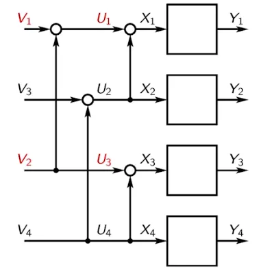
Arıkan uses the same definition as the Medium post, but draws the encoder in a slightly different way. With this definition, the encoder is \(d = u B_N (G_2)^{\otimes n}\), where \(B_N\) denotes the bit-reversal permutation of size \(N = 2^n\).
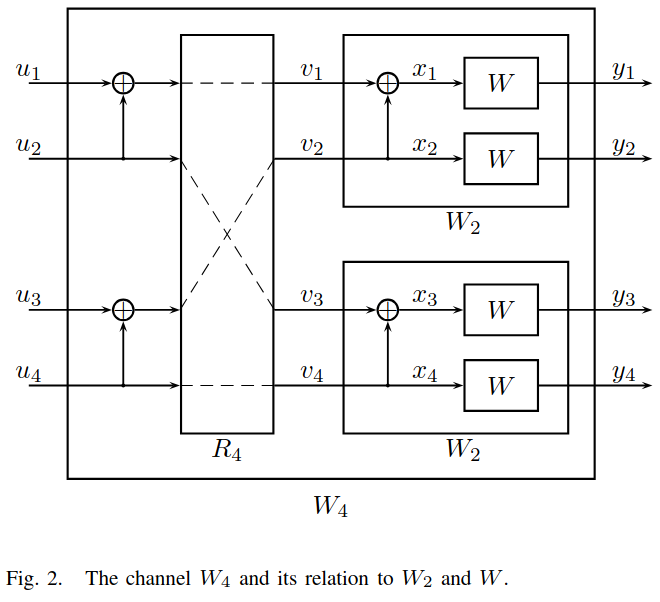
Recall that for the radix-2 FFT, in the decimation-in-time architecture the input is presented in bit-reversed order, while in the decimation-in-frequency architecture the output appears in bit reserved order. This gives some justification for why the bit reversal permutation is appearing here. For Polar codes, the order of the input elements is important when comparing plots of the virtual channel capacities, since the x-axis in these plots follows this order.
The second pitfall is that relatively few sources speak about LLRs. Most sources only treat cases such as a binary erasure channel (BEC) and/or a binary symmetric channel (BSC). In practical applications usually we want to use LLRs or other forms of soft symbols (discarding the amplitude information and using a BSC is the same as hard-decision decoding, which give worse sensitivity). Technically speaking, Polar codes are introduced in the context of binary-input discrete memoryless channels (B-DMCs). Here discrete means that both the input and output alphabets are finite, so this leaves out soft symbols with values in \(\mathbb{R}\). I don’t know if there is a fundamental reason for excluding channels with an infinite alphabet, or if this is just for convenience (for instance, the expressions that Arıkan gives for \(I(W)\) and \(Z(W)\) would need to be written more carefully for general probability distributions, specially if the distribution is not continuous). I guess that the case of a well-behaved continuous distribution on \(\mathbb{R}\) can be recovered from the discrete case by approximation. And nevertheless practical implementations quantize the channel values, so we never really work in \(\mathbb{R}\).
Still this can leave us with the question of how to deal with LLRs in a Polar decoder. Many sources explain how things work for the binary erasure channel, which is good to give examples that help with intuitive understanding, but then they don’t mention how to switch to LLRs. It seems that dealing with soft symbols in Polar decoders is still an active research topic. Nevertheless, I will come back to this when I explain my SC LLR decoder.
The main thing to understand about why Polar codes work is that the Polar encoder generates virtual channels that almost polarize the channel capacity. This means the following. To each input we can assign a reliability. This indicates, briefly speaking, the probability of being able to decode the input correctly assuming that all the previous inputs have been correctly decoded. The reliabilities depend on the channel, but it turns out that if the Polar code is large enough, most of the reliabilities are either close to zero or to one, and moreover the fraction of reliabilities that are close to one is close to the channel capacity. We use the Polar code as an \((N, K)\) linear block code by allocating the \(K\) information bits to \(K\) inputs with high reliability, and forcing all the other inputs to zero. Assuming that the rate \(K/N\) is lower than the channel capacity (which needs to be the case for communication to happen), then the \(K\) inputs with data will have reliabilities very close to one and the receiver will be very likely to be able to decode the message successfully (since it knows that all the other inputs have been forced to zero). The inputs that are forced to zero are usually called frozen inputs.
The natural decoding scheme for Polar codes is the SC decoder, which is well summarized by the following example.

The SC decoder basically tries to work through the encoder circuit in the reverse direction using a depth-first search over a binary tree. Here the way that the encoder circuit is drawn matters, so I will be using the 5G NR convention, since the example is from the “Design of Polar Codes in 5G New Radio” paper.
In the root of the tree, the decoder has a received message of length 8. It knows that the 4 first inputs of the last encoder step can be recovered as the component-wise XOR of the 4 first received symbols (the left half of the codeword) and the 4 last received symbols (the right half of the codeword). It works as best as it can to estimate these 4 XORs. Whenever one of the two symbols in the XOR is an erasure, it cannot know the outcome, so the outcome is an erasure too, but if none of the two symbols is erased, then it can calculate the XOR. It passes the calculated 4-element estimate to the left child in the tree.
Now if we look again to the encoder circuit, we see that we have peeled the last encoder layer and are now working with only the upper half of the diagram. The circuit that remains is now an encoder circuit for a code of half the size, so the algorithm can continue recursively in the same way. This is where the depth-first-search binary tree comes from.
Continuing in this way, we arrive to the leftmost leaf with an estimate for the value of this input. Here there are two options. Either the leaf was an information bit, in which case the estimate we got is the best we can tell about the value of this input, or the leaf was a frozen input, in which case we can ignore our estimate, because we actually know for sure that the input was a zero. In either case, the leaf passes back a hard-decision of the value of the leaf. This is whether we believe that the leaf is a zero or a one.
The parent of this leaf now needs to generate an estimate for the right child. It knows the value of the left child (we assume that our belief/guess is correct; otherwise decoding is simply doomed to fail, because we already have at least one bit error). It also has an estimate for both the XOR of the left and right child, and an estimate for the right child. It now combines these three pieces of data to generate its best estimate for the value of the right child. With the binary erasure channel, the logic is simple. If both the XOR and the right child estimates are erasures, there is nothing we can say, and our estimate for the right child must be an erasure too. If either one of them (or both) is not an erasure, then we can calculate the value of the right child, either by taking it directly (if the estimate for the right child is not erased) or by computing the XOR of the left child value and the estimate we have for the XOR of the left and right children. In any case, an estimate is passed to the right child.
The right child does the same as the left child (it either commits to this estimate if it is an information bit or overrides it with zero if it is a frozen bit), and passes its hard-decision value back to the parent. The parent now has hard-decision values for both children, so it can use this information to generate hard-decision values for its two inputs (which are the XOR of both children and the value of the right child) and pass these hard decision values back to the parent.
The depth-first search algorithm continues in this way until all the leaves have committed to a hard-decision value. This is the decoder’s output.
Now the question is what needs to be changed to work with LLRs instead of binary erasure channel symbols. Conceptually it is still the same. In fact, the paper presents this algorithm using two generic functions. The first function is \(f(\cdot, \cdot)\), which calculates the estimate transmitted to the left child in terms of the estimates we have for the XOR of the two children and for the right child. The second function is \(g(\cdot, \cdot, \cdot)\), which calculates the estimate transmitted to the right child in terms of these two estimates and the committed hard-decision value of the left child.
In the case of LLRs, if we have \(x\) and \(y\) the LLRs of two bits \(a\) and \(b\) and we want \(f(x, y)\) to be the LLR of \(a \oplus b\) (where \(\oplus\) denotes the XOR), the formula is\[f(x, y) = \operatorname{min}^*(x, y) = 2\operatorname{arctanh}(\tanh(x/2)\cdot\tanh(y/2)).\]This formula appears for instance in the introduction of A Simplified Successive-Cancellation Decoder for Polar Codes. The reader familiar with LDPC codes might also recognize it as the formula for the check node message in belief propagation (see (33) in this report, for instance). The connection is clear. For a check node with three variable nodes \(a, b, c\), the message sent to the variable node \(c\) is the LLR for \(c\) given the LLRs for \(a\) and \(b\). Since the LDPC code forces \(a \oplus b \oplus c = 0\), or equivalently \(c = a \oplus b\), this LLR is just the LLR of \(a \oplus b\).
In practice, the formula above for \(\operatorname{min}^*(x, y)\) is rarely used, not only because of performance reasons, but also because of numerical stability, specially when dealing with large LLRs. In my implementation I have used the equivalent expression\[\operatorname{min}^*(x, y) = \operatorname{sign}(xy)\cdot[\min(|x|, |y|) – \log(1 + e^{-| |x| – |y| |}) + \log(1 + e^{-(|x| + |y|)})].\]This has good numerical properties, specially when using the log1p function to calculate the logarithmic correction terms.
Once we have committed to a hard-decision value for the left child bit \(c = a \oplus b\), we can calculate \(g(x, y, c)\), which is a new improved LLR for \(b\), as follows:\[g(x, y, c) = (-1)^c x + y.\](See Section III in A Simplified Successive-Cancellation Decoder for Polar Codes or (2) in Implementation of a High-Throughput Fast-SSC Polar Decoder with Sequence Repetition Node, for instance). The logic behind this formula is that if \(c = 0\), then \(a = b\), and so \(x\) and \(y\) are two independent LLRs for \(b\). Therefore we should add them to obtain an improved LLR for \(b\). If on the contrary \(c = 1\), then \(b = 1 \oplus a\), and so \(-x\) and \(y\) are two independent LLRs for \(b\). Therefore we should add them (computing \(-x + y\)) to obtain an improved LLR for \(b\).
To summarize, the SC LLR decoder works like this. Starting with the channel LLRs for the received message, the decoder processes the encoder circuit in reverse by following a depth-first search in a binary tree. In each node of the tree, a message for the left child is calculated by reducing the left and right halves of the message for that node with a componentwise \(\operatorname{min}^*\). The left child replies with a commitment to hard-decision values \(c\). A message for the right child is calculated by reducing the left and right halves of the message for that node with a componentwise \((-1)^c x + y\) operation. The right child replies with a commitment to hard-decision values \(b\). The node replies in turn with a commitment to hard-decision values \((c \oplus b, b)\). Leaf nodes either commit to a hard-decision value by looking at the sign of the LLR they receive from their parent if they are information bits, or by always replying with a hard-decision zero if they are frozen bits.
Before implementing and testing a Polar decoder, since the PBCHs we have in the recording have high SNR and no bit errors, we can implement a simplified Polar decoder that only works if there are no bit errors. This allows us to validate that the previous steps, such as descrambling, have been done correctly. This kind of decoder works with hard symbols by undoing the encoder circuit, one layer at a time. If there are any bit errors, the output will be wrong. This is the plot of the output of such decoder. We see that most of the bits are zero, which makes sense, because they should be frozen bits.
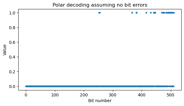
To validate this output, we can check that indeed all the frozen bits are zero in this output. To do this, we need to compute the sets of frozen bits and information bits. For the PBCH this is particularly simple because there are no additional parity bits. The Polar code has \(N = 512\), and the PBCH has \(K = 56\). TS 38.212 Section 5.3.1.2 defines a sequence \(Q_0^{N_{\mathrm{max}}}\) of the 1024 input channels of the maximum Polar code length \(N = 1024\) ordered by reliability. This is a universal sequence, which means that sequences for shorter codes of length \(N < 1024\) are extracted from this one by filtering out the elements which are greater or equal than \(N\). In this way, we obtain the list of the 512 input channels sorted by reliability. The frozen bits are the first 456 channels in this list, and the information bits are the remaining 56 channels. We can check and see that the 456 frozen bits are indeed zero in the output decoded above, which is good evidence that we have implemented the decoding chain correctly so far.
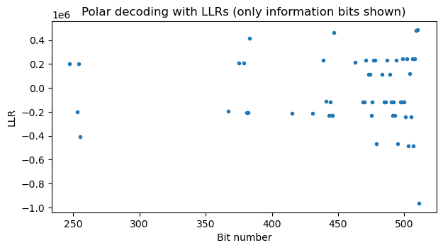
Now that we are confident that we’re on the right track, we can implement and test the Polar decoder using successive cancellation and LLRs. The following figure shows the LLRs that the decoder has computed for each information bit (for each leaf that is not forced to zero). The LLRs for the frozen bits are \(+\infty\) technically speaking, and thus are not shown. This output looks good because the LLRs are well separated from zero. We can also compare the decoder’s hard decision output with the output we obtained above with the no-bit-error decoder and see that they are equal.
Deinterleaving, CRC checking, and descrambling
The next step is to undo the interleaving that is done at the input of the Polar encoder. This interleaving is defined in TS 38.212 Section 5.3.1.1 and has been explained in the PBCH section above. The following two figures show raster maps of all the PBCHs before deinterleaving and after deinterleaving. Recall that the interleaver permutation leaves most of the CRC bits near the end of the message. This is the reason why both plots look somewhat similar. We can see that the CRC area (the last 24 bits) looks more random than the rest, specially in the deinterleaved PBCH.
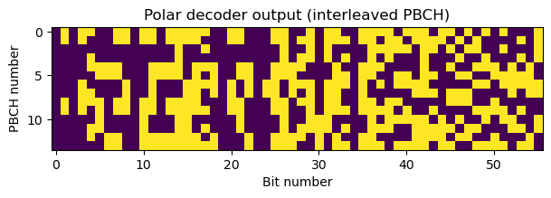
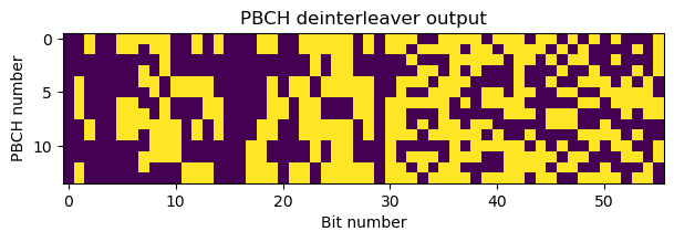
After deinterleaving, we can check the CRC-24, which validates that all the steps up to this point are correct. The CRC used for the PBCH is the CRC24C defined in Section 5.1 in TS 38.212. I have used pycrc to generate a table-driven implementation of this CRC.
Once the CRC is checked, we can discard it, so that only 32 bits remain. Now we need to undo the interleaving and scrambling defined in Sections 7.1.1 and 7.1.2 in TS 38.212. In the cell used in this recording (which has \(\overline{L}_{\mathrm{max}} = 4\)), there are 3 bits which are not scrambled, so we can obtain them right away, by locating where the scrambler has placed them. These are then 3rd and 2nd LSBs of the SFN, and the half-frame bit. The 3rd and 2nd LSBs of the SFN are particularly important, because they define the number \(\nu\) that is used to select which part of the scrambling sequence is applied. The value of \(\nu\) in the PBCHs we are decoding follows the sequence 3, 3, 0, 0, 1, 1, 2, 2, 3, 3, 0, 0, 1, 1. This looks correct, because we know that \(\nu\) increments by one every two radio frames, and in this recording there is one PBCH transmission in each radio frame. The half-frame bit is always zero, which also makes sense because in this recording the PBCH is always transmitted at the beginning of the frame.
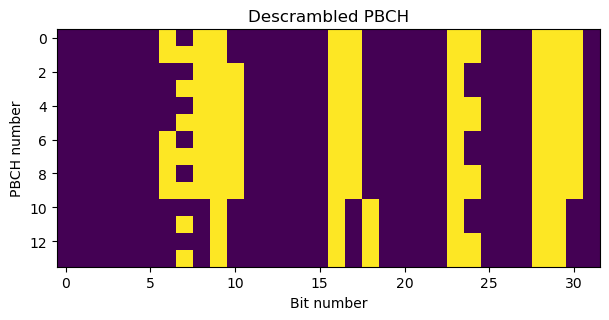
We generate a pseudo-random sequence of length 116 using \(N_{\mathrm{cell}}^{\mathrm{ID}}\) as initialization value and select one quarter of that sequence for each PBCH based on its value of \(\nu\). We use that 29-bit subsequence to descramble, obtaining the following. Most of the bits are zero, which looks reasonable.
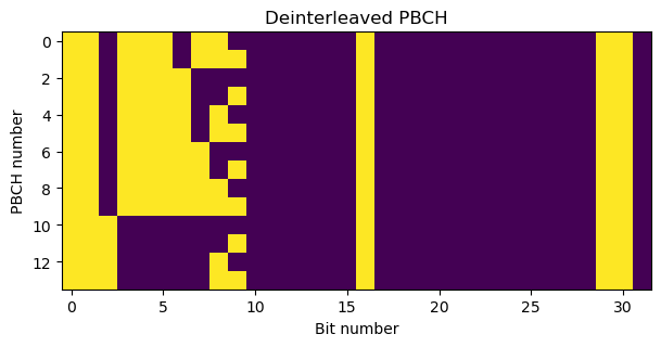
Finally, we undo the interleaver permutation. What we obtain is a 32-bit vector that contains the following fields, in this order:
- The 10-bit SFN. The 6 MSBs of this form part of the MIB ASN.1 message.
- The half-frame bit.
- 3 bits, the first of which is the MSB of the \(k_{\mathrm{SSB}}\) parameter and the other two are reserved. These 3 bits are always zero in this recording.
- The remaining 18 bits of the MIB ASN.1 message.
We can see that the SFN has the pattern of a binary counter, because it increments by 1 in each PBCH transmission, and the remaining fields have static values.
ASN.1 decoding
To perform ASN.1 decoding of the MIB first we need to extract it from the 32-bit PBCH shown in the previous plot. The message is formed by:
- Bit 14 (using zero-based indexing), which indicates the ASN.1 message type.
- Bits 0-5, which are the 6 MSBs of the SFN.
- Bits 15-31, which are the remaining part of the message.
As in my LTE posts, I have used asn1tools to perform ASN.1 decoding. However, asn1tools doesn’t support parametrization, as reported in this Github issue, so it doesn’t work out of the box with the NR RRC ASN.1. I have used the hack described in that issue to work around this limitation. I have downloaded the ASN.1 definitions for the NR RRC from OpenAirInterface5G. The definitions are given in TS 38.331, but it is cumbersome to extract them from this PDF by hand. To make the hack work, I have needed to “flatten” the ASN.1 by putting everything under the same DEFINITIONS block.
The relevant ASN.1 messages for the PBCH are the following.
BCCH-BCH-Message ::=            SEQUENCE {
    message                         BCCH-BCH-MessageType
}

BCCH-BCH-MessageType ::=        CHOICE {
    mib                             MIB,
    messageClassExtension           SEQUENCE {}
}

MIB ::=                             SEQUENCE {
    systemFrameNumber                   BIT STRING (SIZE (6)),
    subCarrierSpacingCommon             ENUMERATED {scs15or60, scs30or120},
    ssb-SubcarrierOffset                INTEGER (0..15),
    dmrs-TypeA-Position                 ENUMERATED {pos2, pos3},
    pdcch-ConfigSIB1                    PDCCH-ConfigSIB1,
    cellBarred                          ENUMERATED {barred, notBarred},
    intraFreqReselection                ENUMERATED {allowed, notAllowed},
    spare                               BIT STRING (SIZE (1))
}

PDCCH-ConfigSIB1 ::=                SEQUENCE {
    controlResourceSetZero              ControlResourceSetZero,
    searchSpaceZero                     SearchSpaceZero
}

ControlResourceSetZero ::=                  INTEGER (0..15)
SearchSpaceZero ::=                 INTEGER (0..15)
The 24-bit message carried in the PBCH is a BCCH-BCH-Message. This message can be a MIB, or something else (which currently reserved for future extensions). The first bit in the BCCH-BCH-Message UPER encoding thus indicates the message type, and the remaining 23 bits are the MIB.
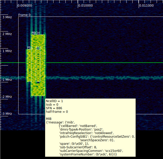
For this recording, the first decoded MIB contains the following data.
{'message': ('mib',
  {'systemFrameNumber': (b'\xdc', 6),
   'subCarrierSpacingCommon': 'scs15or60',
   'ssb-SubcarrierOffset': 8,
   'dmrs-TypeA-Position': 'pos2',
   'pdcch-ConfigSIB1': {'controlResourceSetZero': 0, 'searchSpaceZero': 0},
   'cellBarred': 'notBarred',
   'intraFreqReselection': 'notAllowed',
   'spare': (b'\x00', 1)})}
There are some values in the MIB that we can already check against things that we have found in previous posts. The subcarrier spacing is indeed 15 kHz, which we know from the post about 5G NR demodulation.
The ssb-SubcarrierOffset parameter indicates \(k_{\mathrm{SSB}}\), which is the number of subcarriers between the first subcarrier of the common resource block and the first subcarrier of the SSB. The MSB of this value is transmitted outside the MIB, in one of the extra bits of the PBCH. Here we have seen that this MSB is zero, so \(k_{\mathrm{SSB}} = 8\). This is a value that we have already encountered when looking at the subcarriers occupied by the different signals in the cell. Using the 512-point FFT subcarrier numbering that I have in the Jupyter notebook, the first subcarrier of the SSB has index 136. In the post about the reference signals I explained that the PDCCH DM-RS is generated using a subcarrier indexing that is relative to the start of the common resource block, so to wipe-off the DM-RS pseudorandom sequence, I had to determine the start of the common resource block. I found that it started in subcarrier index 128. We have \(136 – 128 = 8\) as expected. (In this reasoning I’m making a simplification. The PDCCH DM-RS that I demodulated was the one for the SIB1, so it is referenced to CORESET0, whose start in general does not need to match the start of the common resource block. However, in this case, both start at the same point).
A 5G UE works in reverse to how I’ve done in these posts. It first detects the synchronization signals in the SSB and decodes the MIB. By doing this, it knows to which subcarriers the SSB is allocated. After decoding the MIB, it knows \(k_{\mathrm{SSB}}\), so from this and the pdcch-ConfigSIB1 parameter, it calculates where CORESET0 starts. Then it can start to decode the PDCCH to find when the SIB1 is transmitted in the PDSCH.
The parameter dmrs-TypeA-Position indicates the time-domain symbol that contains the first PDSCH DM-RS symbol (and also PUSCH DM-RS) symbol. In this recording we have seen that the PDSCH DM-RS appears in symbols 2, 7, 11 in each subframe. This is consistent with the value of pos2 we have seen in the MIB (note that the PDSCH DM-RS resource element allocation in general is far more complicated than just this parameter, as explained in ShareTechnote).
The parameter pdcch-ConfigSIB1 defines the time-frequency location of CORESET0, which is where the PDCCH for SIB1 is transmitted. The values given in the MIB are indices into fairly complicated tables given in Section 13 in TS 38.213. Here I will only say that these indices imply that CORESET0 has an offset of 0 resource blocks, so its start coincides with the start of the common resource block.
PCAP output
As in the posts about LTE, I have written a PCAP file with the decoded MIBs. The PCAP can then be analyzed with Wireshark. The formatting of the PCAP file is very similar to the one I explained in the post about the LTE PDSCH. The main difference is that mac_nr_info struct should be used to encode the NR frames. The following is a screenshot of Wireshark dissecting these MIBs.

SigMF annotations
In previous posts, I have used SigMF annotations to associate the parameters and decoded data obtained with the notebook with the time-frequency region of the signal to which they refer. Here I have extended my SigMF annotations to add the information obtained by decoding the PBCH. This can be displayed as a tooltip in Inspectrum, as shown here.
Code and data
The work shown in this post can be found in this Jupyter notebook. The SigMF file, the output PCAP file and other supporting files are in the same repository.
One comment