In my previous post I spoke about the recording I did of the Europa Clipper X-band telemetry shortly after launch with one of the Allen Telescope Array antennas. In that post I analysed the recording waterfall and the signal modulation and coding, and decoded the telemetry frames with GNU Radio. In this post I analyse the contents of the telemetry. As we will see, there are several similarities with the telemetry of Psyche. This makes sense, because both are NASA missions that have been launched only one year apart.
AOS frames
The frames transmitted by Europa Clipper are CCSDS AOS Space Data Link frames. The spacecraft ID is 0x9f, which is assigned to Europa Clipper in the SANA registry. There are only two virtual channels in use in the recording. Virtual channel 32, which contains telemetry, and virtual channel 63, which is the only-idle-data virtual channel. There is no operational control field at the end of the frames, but there is a FECF (CRC-16) which is checked and removed by the GNU Radio decoder.
I spoke about virtual channel 63 in the previous post. Each frame in this virtual channel contains an APID 2047 idle Space Packet whose payload is an ASCII text with names of the team members and a quote from a poem written by Ada Limon for the Europa Clipper mission. The APID 2047 Space Packets in virtual channel 32 also contain the beginning of this ASCII text.
Virtual channel 32
Virtual channel 32 contains CCSDS Space Packets using the M_PDU protocol. All the packets from non-idle APIDs contain a 6-byte secondary header which is a timestamp that counts \(2^{-16}\) seconds units since an epoch. According to the SCLK SPICE kernel, the timestamp epoch is nominally 2010-01-01T00:00:00 UTC (the kernel data gives the timestamp 01-JAN-2010-00:01:06.184000, but this is in the TT timescale, and is equivalent to 2010-01-01T00:00:00 UTC). The Space Packets in APID 2047 (the idle APID), do not contain a secondary header.
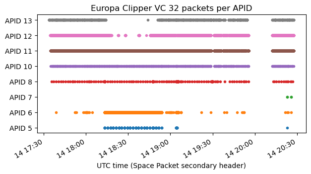
The following figure shows the APIDs that are in use. The gap around 20:00 UTC corresponds to a time period in which the spacecraft was pointing its low gain antenna away from Earth and the telemetry signal could not be decoded.
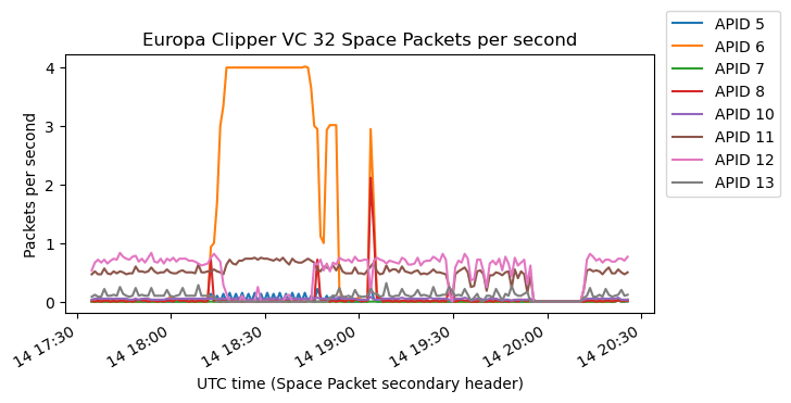
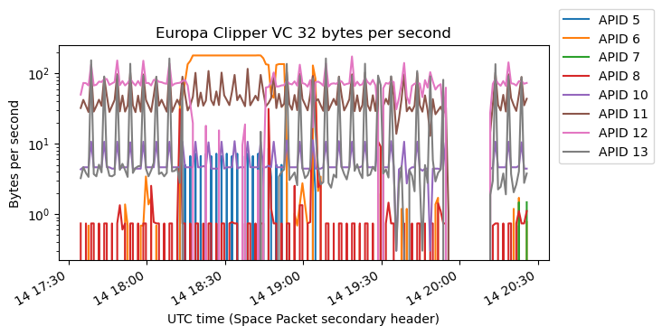
The following two plots show the number of packets per second and bytes per second transmitted in each APID. Usually, most of the data is in APIDs 11 and 12, with APIDs 10 and 13 sending a smaller amount of data constantly. At some point there is a lot of data from APID 6. This takes priority over all the other APIDs except 11, so several APIDs do not transmit anything during this time.
APIDs 5-8
APIDs 5-8 contain “sentences” that start by a 6-byte ASCII tag. This is similar to APIDs 4-8 in virtual channel 0 in Psyche. However, in Europa Clipper the ASCII tags always contain hexadecimal characters, giving tags such as 0F0106. In Psyche, the tags had acronyms such as GNC_16.
Some of these sentences contain ASCII strings. In particular, APID 6 contains UART_HS_ONLY, strings like LV11FLA and several variations, and STOP and COMPLETE. APID 8 contains /eng0/launch_final_config.seq. This is similar to some of the strings I found in the telemetry of Psyche, such as /eng/seq/stop_rotisserie.rel.
I haven’t been able to make much sense of the contents of these sentences.
APIDs 10-13
APIDs 10-13 contain data in key-value format, similarly to Psyche and OSIRIS-REx. A 16-bit tag identifies the variable, implicitly giving the data type and length of the data that follows. The length can be either 1, 2, 4, 8 or 40 bytes (the appearance of 40 byte values is new compared to these other spacecraft). All the 8-byte values seem to be big-endian float64, while some of the 4-byte values are float32 and others are integers. As usual, going through the telemetry to collect a list of all the tags in use and their associated value lengths has been a manual time consuming process. There are a total of 5571 keys in the recording, with 150, 1240, 2398 and 1950 of them used in APIDs 10, 11, 12 and 13 respectively.
After collecting a complete list of keys and lengths and parsing all the telemetry from these APIDs, I have tried to make reasonable plots of most of the variables by guessing their data types and grouping them according to their ranges of values. See the Jupyter notebook for the complete set of plots.
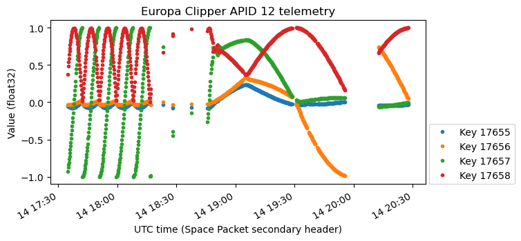
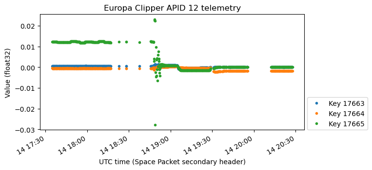
After looking at these plots, the only variables that I have been able to identify with confidence are the ADCS attitude quaternions and angular rates. These appear in APID 12 and have float32 values. The plots below show the telemetry keys in which they are found. The gaps without data around 18:30 UTC are caused by APID 6 having higher priority, impeding the transmission of APID 12 data.
ADCS telemetry
The four telemetry channels shown above are clearly attitude quaternion data, because the sum of their squares is always very close to one. When reverse engineering attitude quaternions, there is usually some guesswork or trial and error needed to determine if the quaternions represent the body to ICRF rotation or vice versa, and whether the format is scalar-last or scalar-first. Here body to ICRF scalar-last seems to be the correct interpretation, as it has also been the case in other NASA missions. The quaternions are normalized to have a non-negative real part.
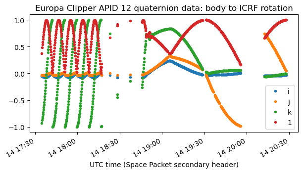
My procedure for analysing attitude quaternions and checking that my interpretation is correct is always very similar. I take a time \(t_0\) and compute \(h(t) = q^{-1}(t) q(t_0)\). These new quaternions should represent the relative rotation in body coordinates from time \(t_0\) to time \(t\). Frequently, a spacecraft rotates with a constant axis in body coordinates and constant angular rate, so by plotting the axis and angle of rotation of \(h(t)\) we can tell if this is the case.
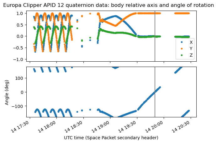
The following plots show the axis and angle of rotation of \(h(t)\) for four different choices of the reference time \(t_0\), which is depicted as a vertical grey line in each plot. In the first plot we see that until around 18:50 UTC, Europa Clipper was rotating at a constant rate on an axis quite close to the Z body axis.
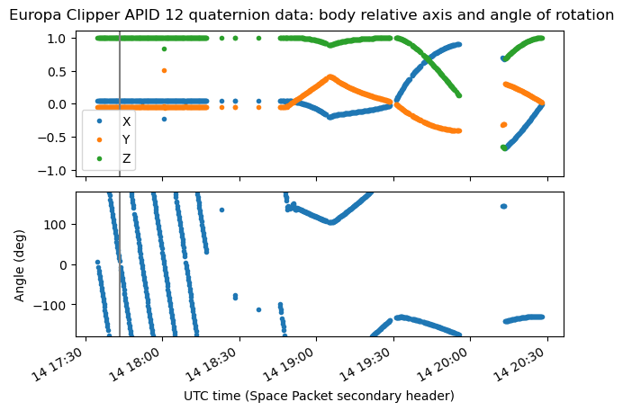
The next two plots are somewhat more complex, as the axis and angular rate is not constant. They correspond to a transition between the rotation about the Z body axis and the rotation in the fourth plot.
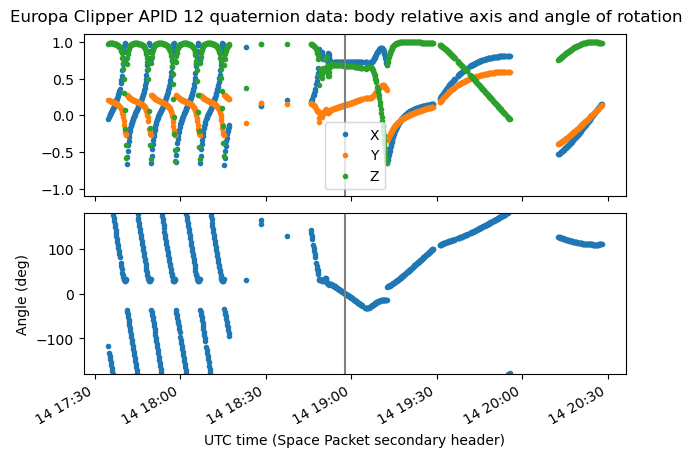
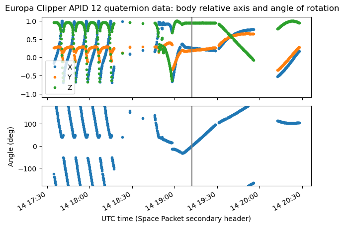
In the last plot we see that after 19:30 UTC the spacecraft is rotating about its Y body axis at a constant rate. The angular rate is much slower than in the rotation at the beginning of the recording.
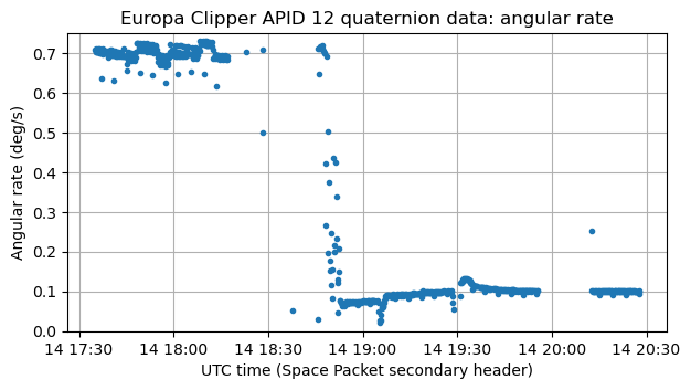
The following figure shows the angular rate described by the attitude quaternions. This has been computed as the angle of the quaternion \(q^{-1}(t_{n+1}) q(t_n)\) divided by \(t_{n+1} – t_n\). We can see that the faster rotation about the Z axis in the beginning of the recording has a rate of 0.7 deg/s (7 revolutions/hour), while the slower rotation about the Y axis at the end of the recording has a rate of 0.1 deg/s (1 revolutions/hour).
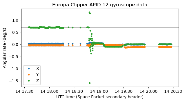
With this knowledge we can verify the scale of the angular rates (potentially gyroscopes) telemetry. In this case, the float32 telemetry variables have units of rad/s. Here they are plotted in deg/s with horizontal lines at 0.7 deg/s and -0.1 deg/s.
When a spacecraft is rotating about one of its body axes, that axis is often pointed in some particular direction, for some particular purpose. For instance, in the post about the Psyche telemetry, we saw that in the rotisserie mode it rotated about its X body axis and pointed this axis towards the Sun in order to maintain the solar panels perpendicular to the Sun vector. Another example is pointing towards Earth the body axis where an antenna is located. So the next thing I usually do to analyse the attitude quaternions is to compute the orientation in the ICRF frame of the body axis of rotation and compare it with vectors such as the Sun vector and Earth vector.
However, in the case of Europa Clipper the situation is somewhat puzzling. During the faster rotation about the Z body axis, the +Z body vector is almost aligned with the +Z ICRF vector.
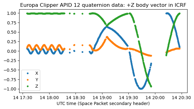
And during the slower rotation about the Y body axis, the +Y body vector is almost aligned with the +Y ICRF body vector.

There might be some significance about the +Z ICRF vector, because it points in the direction of the Earth north pole. So in this faster rotation the spacecraft would be rotating its XY body plane parallel to the Earth equator. However, I don’t think there is anything significant about the +Y ICRF vector. I can’t think of any reason why it could make sense to align the +Y body vector of a spacecraft with the +Y ICRF vector. So I was even thinking that I had made a mistake with the calculations.
To check for mistakes, I have compared these plots with the SPICE CK kernels. There is no kernel that covers 2024-10-14. The nearest available kernel is clipper_sc_rq_241015_241017_day290_v01.bc, which starts at around 2024-10-15T11:00 UTC. Nevertheless, when we plot the +Y body vector in ICRF coordinates according to this SPICE kernel, we see that it begins almost pointing to the +Y ICRF vector, as a continuation of how the plot above ended at 2024-10-14T20:30 UTC. This continues until the beginning of 2024-10-16, when the spacecraft changes attitude.
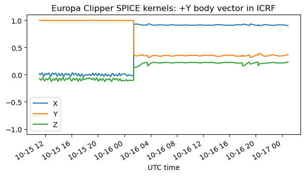
If we plot the +Z body vector in ICRF coordinates according to the SPICE kernel, we see that while the spacecraft has its +Y body vector aligned to the ICRF +Y vector, it is still rotating about the Y axis at a rate of one revolution per hour, as it was doing at the end of my recording. This makes me confident that my analysis of the telemetry quaternions is correct.

At some point at the beginning of 2024-15-16, the spacecraft stops rotating and maintains a new attitude. To understand this attitude, we can plot the Sun and Earth vectors in body coordinates. We see that the Sun vector is well aligned with the -Y body vector, and the Earth vector tries to be aligned with the -Z body vector (since the Sun-spacecraft-Earth angle is not 90 deg, the alignment cannot be perfect, and there is an error in the Y coordinate).
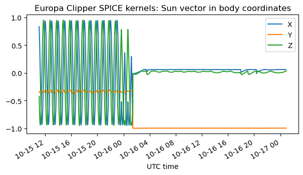
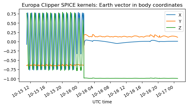
At this point it is useful to read the frame kernel to understand how the spacecraft body axes are defined and where are each of the spacecraft components placed. Looking at a 3D model of Europa Clipper is also useful. The solar panels are placed along the X axis. They can rotate about this axis. The high-gain antenna points towards the -Y axis. There are low-gain antennas on the +Y, -Y and -Z faces. The nadir-facing instrument deck is on the +Y face. So the goal of pointing the -Y axis towards the Sun and the -Z axis towards Earth might be to keep the instrument deck hidden from the Sun while being able to orient the solar panels perpendicularly to the Sun and aiming the -Z LGA towards Earth for communications.
The following plot shows the Sun vector in body coordinates using the telemetry decoded from the recording. We see that during the faster rotation about the Z axis the Sun periodically becomes almost aligned with the X axis of the spacecraft, which causes the solar panels to be poorly illuminated regardless of how they are rotated about the X axis. This is quite intuitive from the geometry. The spacecraft has aligned its solar panel axis parallel to the equator, and the Z axis with the Earth rotation axis. The spacecraft is rotating about the Z axis. Since the Sun is close to the equator, the spacecraft X axis becomes almost aligned with the Sun twice every rotation.
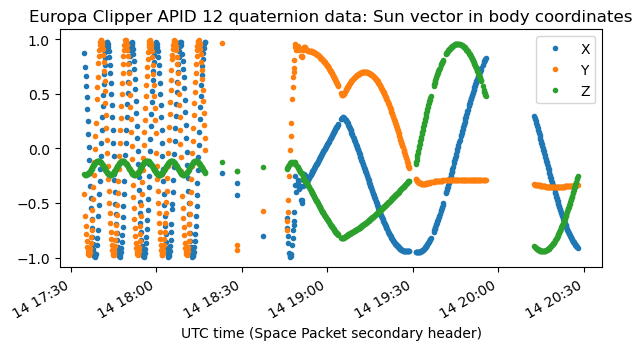
Similarly, when the spacecraft is pointing its +Y body vector to the +Y ICRF vector and spinning about its Y axis, the Sun also becomes close to aligned with the X axis twice every rotation. This happens because since the launch date was within a few weeks of the Autumn equinox, the Sun vector is close to the -X ICRF vector.
We can also plot the vector joining the spacecraft and the Allen Telescope Array in body coordinates. During the faster rotation about the Z axis, the Z coordinate of this vector is somewhat negative. This is because the spacecraft escape trajectory was aimed slightly north of Earth’s equatorial plane. During the slower rotation about the Y axis, the Y coordinate is close to -1. This also makes sense. Since the launch happened close to the Autumn equinox, the Earth velocity vector would be close to the +Y ICRF vector. The escape trajectory would be in the direction of the Earth’s velocity vector in order to set Europa Clipper on an elliptical orbit with an apoapsis beyond the orbit of Mars (see the trajectory animation from Wikipedia). So from the point of view of the spacecraft, the Earth would be towards the -Y ICRF vector. Since the +Y ICRF and body vectors were aligned, this explains why the ATA vector had a large negative Y component in body coordinates.
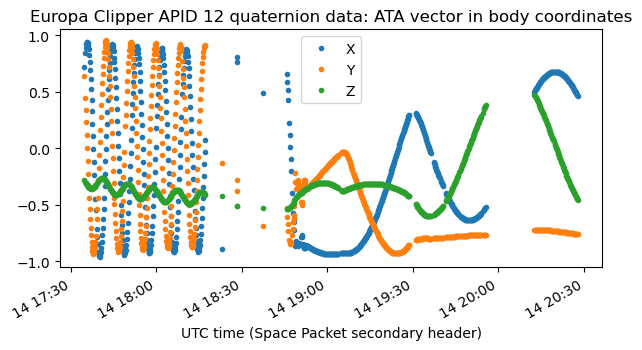
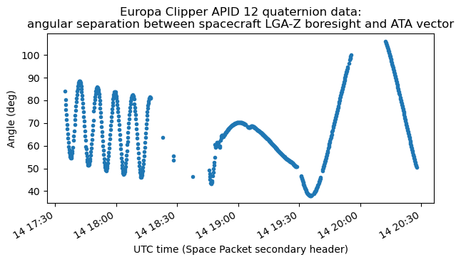
The main reason why the expression of the vector joining the spacecraft and the Allen Telescope Array (or Earth) matters is because it determines if the antennas are pointed towards Earth. The signal drop we have seen around 20:00 UTC in the recording is consistent with the spacecraft using the LGA -Z antenna. This antenna is on the -Z face of the spacecraft, and is actually tilted 15 deg towards the -Y axis. The plot below shows the angle between the boresight of this antenna and the ATA vector. During the signal drop, the angle exceeds 100 deg, which explains the lack of signal.
Other interesting telemetry channels
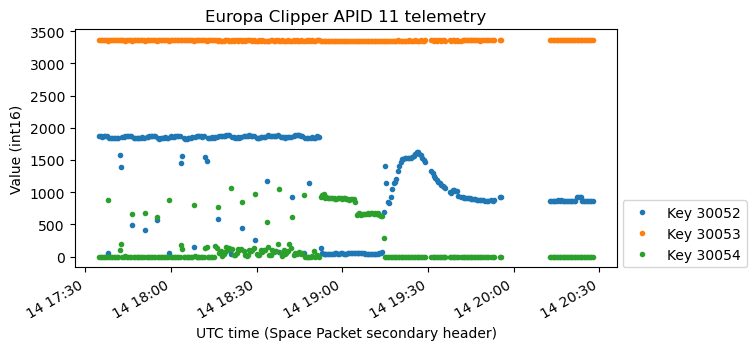
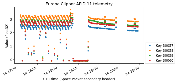
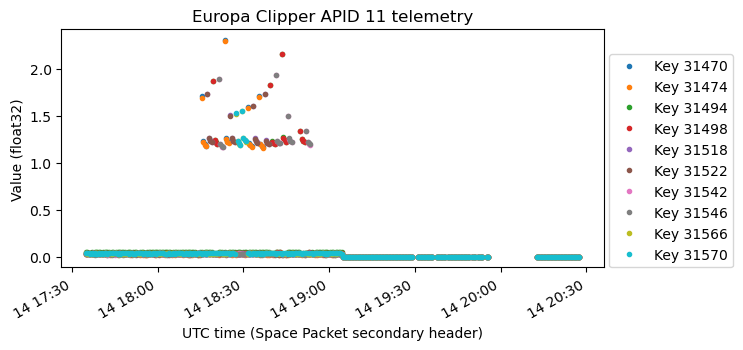
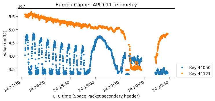
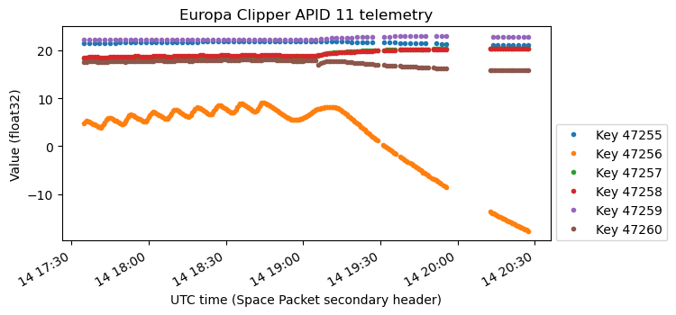
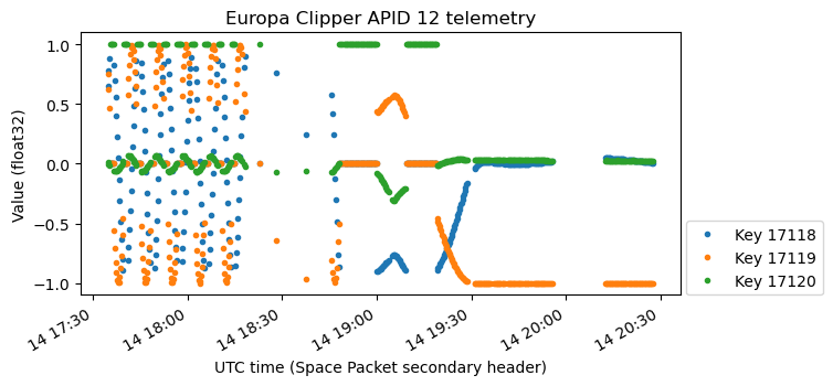
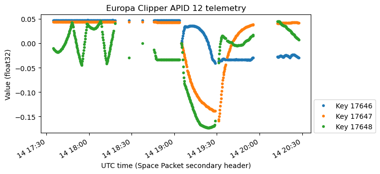
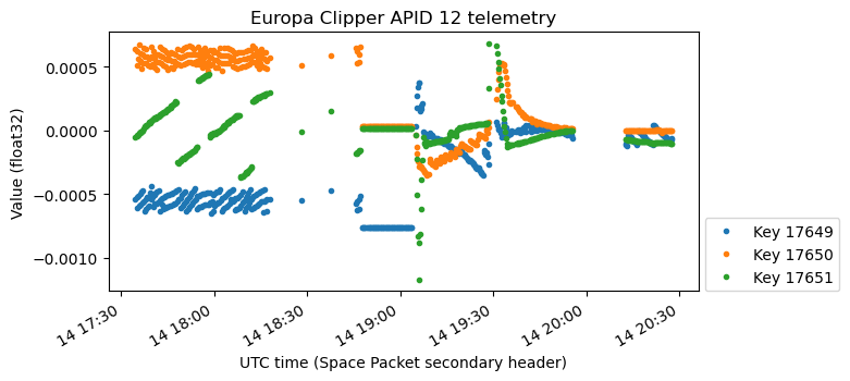
Since we now have a clear picture of how the spacecraft was rotating, we can see the effects of this rotation in other telemetry channels. There are several possible reasons why a rotation may affect telemetry variables: thermal, electrical (solar panel output), ADCS related (other attitude determination variables, reaction wheels…), uplink receiver related (signal strength…), etc.
Nevertheless, understanding what these variables mean just from their plots can be tricky without a detailed knowledge of the spacecraft systems. Here I haven’t able to identify what they are, but I will show a list of the plots that look more interesting. The complete list of plots is in the Jupyter notebook.

40-byte telemetry channels
I have mentioned that some of the telemetry variables are 40 bytes, which is something that I hadn’t encountered before in this key-value format used by NASA missions.
One of the channels, with key 3201, always contains the ASCII string /eng0/cb/cbm_ctl_telemetry_selection_fil in these 40 bytes. Some of the other channels contain shorter ASCII strings such as e_launch, _launch, 0039_0466597005-0515276.
The data in each of these channels doesn’t change much. Here is a raster plot of key 3522, where each value on this key is a line of the plot. Most of the bytes in the 40-byte value stay constant throughout the recording.
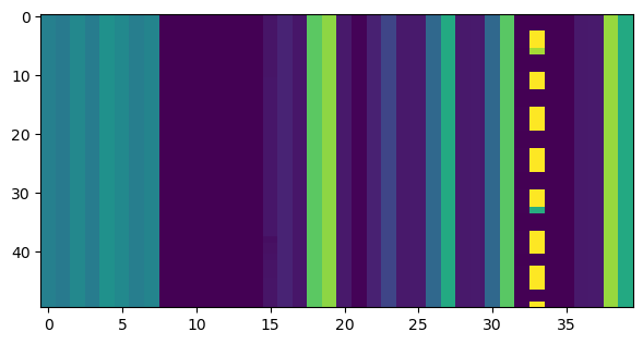
I haven’t been able to pull out any interesting information from these 40-byte values.
Code and data
The analysis in this post has been performed in this Jupyter notebook. The raw IQ recording and the file containing the decoded AOS frames are linked at the end of the previous post.
One comment