NEXUS, also called FO-99, is a Japanese Amateur satellite built by Nihon University and JAMSAT. It was launched on January 2019, and one of its interesting features is a π/4-DQPSK high-speed transmitter for the 435 MHz Amateur satellite band.
I was always interested in implementing a decoder for this satellite, due to its unusual modulation, but the technical information that is publicly available is scarce, so I never set to do it. A few days ago, Andrei Kopanchuk UZ7HO asked me a question about the Reed-Solomon code used in this satellite. He was working on a decoder for this satellite, and had some extra documentation. This renewed my interest in building a decoder for this satellite.
With some help from Andy regarding the symbol mapping for the π/4-DQPSK constellation, I have made a decoder GNU Radio flowgraph that I have added to gr-satellites.
The modulation used by NEXUS is actually listed as π/4-QPSK 38k4 in several sites, such as in the satellite operations schedule. However, to be more precise, the modulation is 19.2 kbaud π/4-DQPSK. This means that each pair of bits is encoded as the phase shift between one symbol and the next one. There are four possible phase shifts: \(\pi/4\), \(3\pi/4\), \(5\pi/4\), and \(7\pi/4\).
Thus, if the constellation is rotated appropriately, the constellation symbols are \(1\), \(i\), \(-1\), \(-i\) for even symbols, and \((1+i)/\sqrt{2}\), \((-1+i)/\sqrt{2}\), \((-1-i)/\sqrt{2}\), \((1-i)/\sqrt{2}\) for odd symbols. These are two QPSK constellations staggered by a 45 degree rotation.
The symbol mapping used by NEXUS to transform the phase differences between adjacent symbols into dibits is shown in the table below, together with the more usual QPSK symbol mapping that assigns to the constellation symbols \(z = \pm 1 \pm i\) the dibit given by \((\operatorname{Re}(z)+1)/2\), \((\operatorname{Im}(z)+1)/2\) (here the function \(t \mapsto (t+1)/2\) represents justs a bipolar to unipolar transformation, so that the symbol mapping accounts essentially to taking the real and imaginary parts of the symbol, which is very useful for decoding).
| Phase difference | NEXUS symbol mapping | QPSK symbol mapping |
|---|---|---|
| \(\pi/4\) | 00 | 11 |
| \(3\pi/4\) | 01 | 01 |
| \(5\pi/4\) | 11 | 00 |
| \(7\pi/4\) | 10 | 10 |
Comparing the NEXUS symbol mapping with the usual QPSK mapping, we see that we can convert between them by inverting the bits and swapping I and Q, so this gives an effective way of decoding the NEXUS symbol mapping. However, the NEXUS symbol mapping can be constructed in a more natural way by taking the usual order of the 2-bit Gray code, indexed by the phase differences in increasing order.
The baudrate (symbol rate) for the NEXUS signal is 19.2 kbaud. Probably the signal is listed as 38k4 because the bitrate (not taking FEC into account) is 38.4 kbit/s.
The frames transmitted in this signal are standard CCSDS Reed-Solomon frames with a frame size of 223 bytes (not counting the 32 Reed-Solomon parity check bytes). The dual basis is used for the Reed-Solomon code.
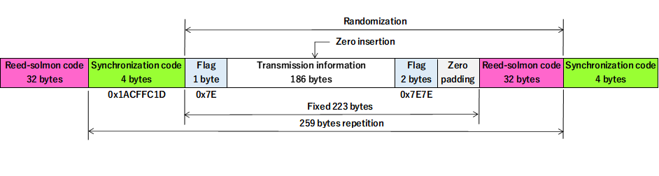
The payload of each Reed-Solomon codeword contains a single AX.25 frame, using some sort of HDLC encoding. The best way to describe this encoding is that if we take the payload and invert the bit ordering in each of the bytes (i.e., if we replace \(b_7b_6\ldots b_1b_0\) by \(b_0b_1\ldots b_6b_7\)), then we obtain a perfectly compliant AX.25 frame using HDLC. Bit stuffing, the LSB byte ordering of AX.25, and the CRC-16 CCITT are used. The payload starts by a single 0x7e flag, and after the AX.25 frame, 0x7e flags are repeated until the end of the payload. These final 0x7e flags may or may not be byte-aligned depending on the amount of bit stuffing. This is represented by the image below, which Andy has shared. Note that the zero padding field should actually be 0x7e padding.
This frame structure is quite interesting, because it resembles FX.25 in that an AX.25 frame is wrapped by an outer FEC layer. FX.25 is designed to be backwards compatible with AX.25, since an AX.25 receiver will just ignore the wrapping. However, the NEXUS framing is not AX.25-compatible, because of the CCSDS synchronous scrambler and also because the bit ordering in each byte needs to be inverted.
I am curious about why this frame structure was used, since it doesn’t give backwards compatibility with AX.25 receivers (and in any case, there are no 19k2 π/4-DQPSK AX.25 modems that I know of, so backwards compatibility is not very useful). If backwards compatibility is not desired, then it seems much more simple to include the AX.25 frame directly into the Reed-Solomon codeword payload, without using any of the HDLC features (though some way to mark the frame end or length would be needed).
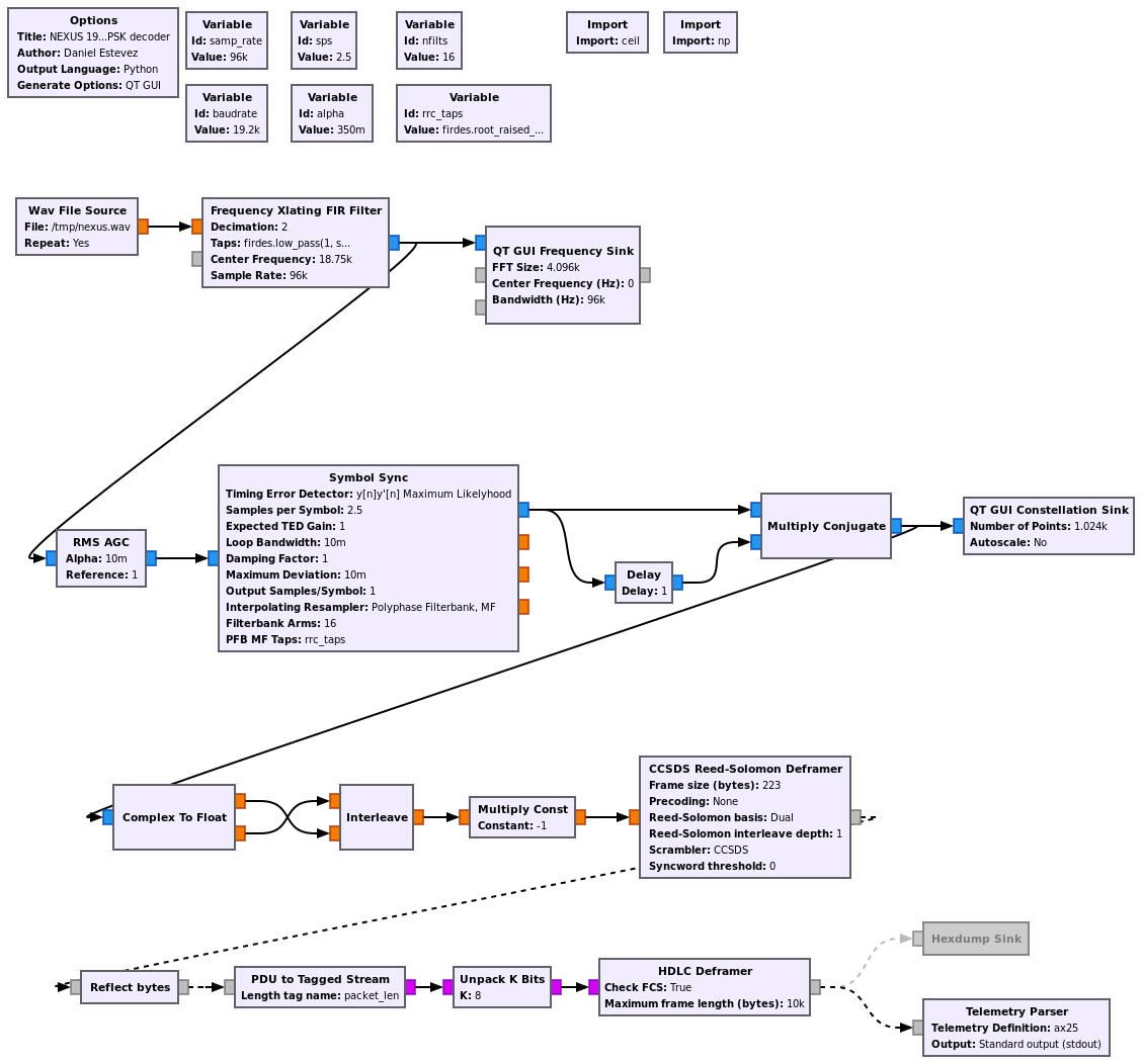
The GNU Radio decoder flowgraph is shown in the figure below. The recording I’ve used has been provided by Andy and can be downloaded here. It uses 96ksps real sampling and the signal is centred at about 18750 Hz.
A Frequency Xlating FIR Filter is used to move the signal to IQ baseband at 48ksps. Then there is an AGC and the Symbol Sync block, that performs RRC matched filtering and symbol clock recovery.
Each symbol is multiplied by the complex conjugate of the preceding symbol in order to get a constellation that gives the phase difference between adjacent symbols. This constellation is decoded to dibits by using the relation with usual QPSK constellation explained above.
Then the gr-satellites CCSDS Reed-Solomon deframer is used to synchronize to the CCSDS frames, descramble and decode the Reed-Solomon code. The bytes in the payload are reflected to invert the bit ordering and then sent into the HDLC deframer, which checks the CRC-16 and outputs the AX.25 frames.
Note that this decoder uses non-coherent demodulation of the differential constellation. Another approach would be to use coherent decoding by including a Costas loop. One way to do so would be to contra-rotate every other symbol by 45 degrees at the output of the Symbol Sync block, in order to compensate for the constellation staggering. Then a regular QPSK Costas loop can be used. At the output of the Costas loop, the 45 degree contra-rotation can be undone. Then the decoding can proceed as in the non-coherent case, by multiplying each symbol with the complex conjugate of the previous one.
Hello.
Could you please provide a GNU Radio block diagram using the Costas loop?
Thank you in advance.
P.S.
I’m from Japan and I’m not very good at English.
I managed to build it using AI.
Thank you very much.