Last Sunday, Julián Fernández EA4HCD, released a high altitude balloon carrying a LoRa payload as a preliminary test for the FossaSat-1 pocketqube that he is devolping with Fossa Systems. You can see a video of the release in this tweet. The balloon was launched near Madrid, and burst at an altitude of approximately 24km, having travelled some 180km southeast.
The payload had two transmitters: An SX1278 LoRa transceiver transmitting at 434.5MHz with 10mW alternating between LoRa and RTTY, and an 868MHz 25mW LoRa transceiver that was received on The Things Network. Simple groundplane 1/4-wave monopole antennas were used.
I went to the countryside just outside my city, Tres Cantos, and set up a station to record the transmissions on 434.5MHz. The station consisted of a 7 element yagi by Arrow Antennas, set in vertical polarization and placed on a camera tripod on the roof of my car, and a FUNcube Dongle Pro+. This is a brief analysis of the recording.
I was able to receive the signal from the balloon since shortly after launch, at 15:37 UTC, until 18:45 UTC, when I took the station down. The balloon burst a few minutes before 19:00 UTC, and the payload quickly descended to ground, as it had no parachute. The recording was made at 192ksps with a centre frequency of 434.5MHz. At some point I changed the centre frequency to 434.502MHz because the RTTY signal went too close to the FUNcube Dongle centre spur due to the transmitter’s frequency drift.
The recording can be downloaded from this Zenodo publication. It is in Linrad raw file format. It can be read as a little-endian int16 IQ file by skipping a 41-byte header at the beginning of the file.
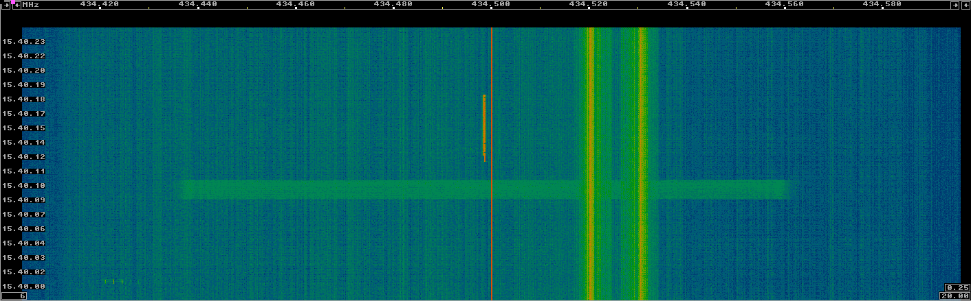
The figure below shows the spectrum of a segment of the recording in Linrad. Approximately every 30 seconds a LoRa beacon was transmitted followed by an RTTY beacon. The mode used by LoRa was SF11 125kHz, while RTTY used 240Hz of shift, 45 baud, 7bit ASCII, and 1 stop bit. There are also moderate levels of interference, formed by wideband interference and some narrowband interference around 434.525MHz. I do not know the sources of this interference.
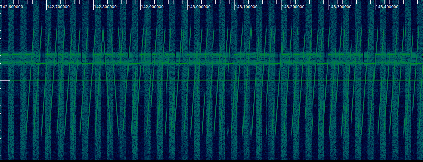
The figure below shows a detail of the LoRa beacon in Inspectrum. The characteristic chirp modulation is visible. Also, the wideband interference is seen to have a pulsed pattern.
The RTTY signal was decoded in real time using fldigi. The payload transmitted its latitude and longitude, obtained from a uBlox M6 GPS, its height, obtained from a BMP280 barometer, and the temperature. I used the position data to aim the antenna. Unfortunately, the GPS stopped updating its position above 18km of altitude, due to CoCom limitations. The signal had a lot of frequency drift, making decoding RTTY quite tricky.
Julián tells me that he was unable to decode the LoRa transmissions at 434.5MHz due to the frequency drift. On the other hand, several gateways from The Things Network received the 868MHz LoRa transmissions, so perhaps this transmitter used a better oscillator, or the SF7 125kHz mode used in 868MHz tolerates drift better.
I have tried to decode the LoRa beacons in the recording with gr-lora, but so far I haven’t obtained anything. Probably it is due to the frequency drift, or maybe due to a not so good support of the SF11 mode in gr-lora.
I have also processed the recording to compute estimates for the power of the LoRa and RTTY signals. The RTTY power is simple to compute: I have used the signal plus noise power in 5kHz bandwidth, in order to be able to ignore the transmitter drift. For LoRa, I have used the following signal processing.
First, the signal is dechirped assuming an upchirp. To do so, I have used something which I would call the IQ equivalent of a Shepard tone. This is a signal with continuous phase and frequency and such that its frequency always increases at a constant rate. Of course it is possible to do this without quickly overflowing things due to aliasing: once the frequency gets to \(f_s/2\), it aliases back to \(-f_s/2\), so in reality the frequency we are generating is a saw-tooth between \(-f_s/2\) and \(f_s/2\) (here \(f_s\) denotes the sample rate).
The more conventional way of performing dechirping would be to replicate what the transmitter is doing and generate a chrip whose frequency is a saw-tooth between -62.5kHz and 62.5kHz. The problem with this is that, unless this chirp is aligned in time with the LoRa signal, the LoRa chirps will break into two tones at different frequencies due to the frequency jump of the dechirping signal (see my post about dechirping CODAR for more information).
The Shepard tone doesn’t require alignment and it never breaks the LoRa chirps into two tones, since it has continuous frequency and phase. One disadvantage of the Shepard tone is that it places each of the 10 upchirps forming the LoRa preamble at a different frequency, while the more conventional method puts them in the same frequency.
To generate this Shepard tone, we must know the slew rate, or chirp rate, of the LoRa chirps. A LoRa mode has two main parameters, the spreading factor \(S\) and the bandwidth \(B\). The duration of each chirp is \(2^S/B\), and each chirp covers a bandwidth \(B\), increasing from \(-B/2\) to \(B/2\). Thus, the slew rate is \(B^2/2^S\). In our case, we have \(S = 11\) and \(B = 125kHz\), so the slew rate is approximately 7.6MHz/s.
The LoRa signal dechirped with the Shepard tone is shown in the figure below. Note the 10 tones corresponding to the 10 preamble upchirps.
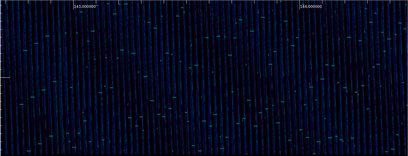
After dechirping, a 1024 point FFT is computed. At a sample rate of 192ksps, this gives us an FFT length of 5.3ms. Since the duration of each chirp is 16.4ms, the dechirped tones occupy several FFT windows, so at least some FFT windows are guaranteed to be filled completely with a dechirped tone, regardless of temporal alignment. The maximum amplitude among all the FFT bins is taken as the estimate of the LoRa signal power.
The GNU Radio implementation of this algorithm is shown in the figure below. The LoRa signal comes from the top.
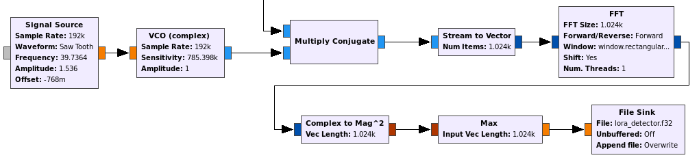
This kind of algorithm works well for estimating the LoRa signal power during the 10 preamble upchirps, ignores the two downchirps marking the end of the preamble, and works moderately well during the data despite the frequency shifts, since the FFT windows are shorter than a complete chirp. In fact, the figure above shows that there are still many relatively long dechirped tones during the data section.
The output of this algorithm is then averaged in segments of 300 FFTs, or 1.6 seconds. This guarantees that at least one averaging window is completely occupied by a LoRa packet, regardless of synchronization.
The results of these power estimators are shown below, comparing the LoRa and RTTY signals. Of course, both follow a very similar behaviour, since they use the same transmitter and antenna.
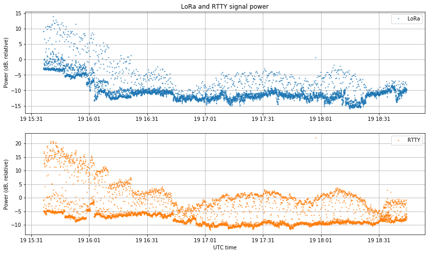
It would be interesting to plot signal power against distance. According to free space path loss, we should see an inverse square law dependence between power and distance.
The plots for this post have been done in this Jupyter notebook. The signal processing has been done in this GNU Radio flowgraph. To run the flowgraph, a FIFO is first created using
mkfifo /tmp/sonda.fifo
and then the recording is sent through the FIFO skipping the header by doing
tail -c +42 recording.raw > /tmp/sonda.fifo
This allows us to read the recording directly in GNU Radio as an int16 IQ file.
Great write-up as always! And very timely… I recently helped monitor a high-altitude balloon flight from a local school here. The 2m APRS signal was very strong, of course, but I was VERY impressed with the 70cm LoRa beacon! Here is a screen shot of the RF in GQRX:
https://www.qsl.net/k/k4kdr//images/gqrx-lora3.png
… I was sorry that I could not decode the LoRa telemetry for that flight, but since then I have purchased a LoRa RX board for Raspberry Pi:
https://store.uputronics.com/index.php?route=product/product&path=61&product_id=68
… and will be ready if anyone flies using that mode again!
My tests with LoRa have shown higher SF are unusable unless a really super stable TCXO is used. I’m even considering OCXO or GPSDO for testing the lower datarate modes.
The drifting frequency while the packet is going on destroy RX capabilities in LoRa. That problem is much more evident with higher SF, that produces longer TX times, making all the frequency stability a much more important issue.
LoRa handles very well frequency offsets between devices but handles very bad drifting signals…. a few Hz drift during packet transmission is enough to not receive anything.
With a drifting (normal) TCXO higher bandwidths and lower SF is the only way to get reliable communication: whatever that makes the TX time shorter. That is one of tbe reasons The Things Network uses SF7 by default.
Next time, the 125 kHz / SF7 should work twice as well in 433 as it has in 868 MHz.
Greetings
Hi Miguel Ángel,
That is a very appropriate remark. It is not specific to LoRa. Every modem that lowers the bitrate in order to increase sensitivity needs a more stable channel (including transmitter and receiver clock drift). In a very general sense, if few bits are transmitted and the channel changes slowly, the receiver needs to determine fewer unknowns, so it can achieve higher sensitivity.
I don’t know the reason for using SF11 in the high altitude balloon, but it certainly makes things more difficult. A lower spreading factor should have worked well, given that the signals were always rather strong. In fact, 45 baud RTTY, which is not a weak signal mode by any means, was often copied correctly (except when the drift was too bad).
I think this is also very relevant for FossaSat-1 or any other LEO satellites trying to use LoRa. Even if computer Doppler correction is done on the receiver, there is still an important residual Doppler due to imperfect TLEs.