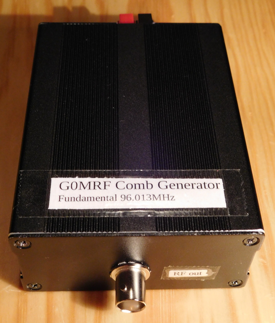
A comb generator is essentially an RF oscillator whose output is amplified in a non-linear fashion, so that plenty of harmonics are produced. This is an easy way of producing microwave signals. The G0MRF comb generator was originally designed as a 2.4GHz signal source, to help in the alignment of receivers for the amateur radio satellite S-band. It has a 96.013MHz crystal oscillator, so its 25th harmonic falls at 2400.325MHz, right in the satellite allocation of the 13cm amateur band. Its harmonics are usable up to at least 10GHz, so this can be an useful tool when working with microwave equipment.
In fact, several other harmonics fall on the amateur bands: The 13th harmonic is 1248.169MHz. This is inside the 23cm amateur band, but quite far from the narrow-band segment, which is at 1296MHz. The 24th harmonic is 2304.312MHz. This falls inside the 13cm band. Indeed, 2302MHz is used for EME in some parts of the world. The 36th harmonic is 3456.468MHz, in the 9cm band, but far from the narrow-band segment. The 59th harmonic is 5664.767MHz, in the 6cm band. This is in the satellite uplink segment and quite near the first narrow-band segment, which is at 5668MHz. The 60th harmonic is 5760.780MHz, right in the second narrow-band segment of the 6cm band. The 105th-109th harmonics all fall in the 3cm band. In particular, the 108th harmonic is 10369.404MHz, which is in the narrow-band segment of the 3cm band.
This is a nice kit which is quite easy to build. Most of the components are through-hole, and it can be put together fairly quickly. I built my kit during the Christmas holidays, but I’ve had the PCB lying around until I installed it in a project box yesterday. Here I describe the kit briefly and show the extruded aluminium case I’ve used.
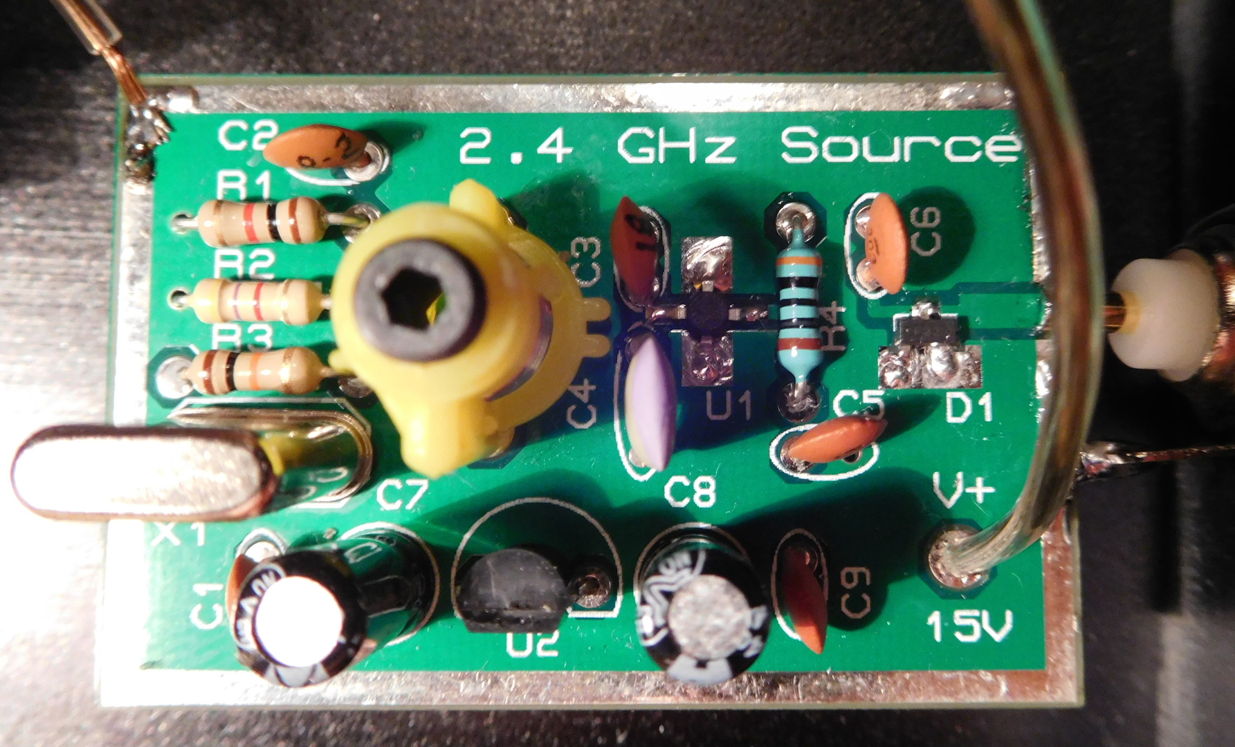
The schematic of the kit is simple: a crystal oscillator produces a 96.013MHz signal which is amplified by a MAR3SM monolithic amplifier. The signal is then clipped by an HSMP-3822, a pair of back-to-back PIN diodes. This generates a lot of harmonics. Refer to G0MRF’s description for more information on the circuit.
The surface mount parts in the kit are the HSMP-3822 and a BFS17, which is used in the crystal oscillator. Both of these are SOT23. To tell them apart, note that the HSMP-3822 is marked “F2” and the BFS17 is marked “E1p”. The MAR3SM is also surface mount. The remaining parts are through-hole. The BFS17 is soldered on the back side of the PCB, and everything else goes on the front.
The circuit is designed to run from 12V, so the kit includes a 78L12 regulator to allow feeding it with unregulated 15V. Of course, the regulator can be omitted and in this case the kit should be fed with regulated 12V. This is a bit inconvenient, because many amateur radio equipment runs at 13.8V, which is a bit too high to use without the regulator and a bit too low to use with the regulator. I’ve checked the datasheet and the regulator has a typical drop-out voltage of 1.7V, so in principle it should be possible to feed it with 13.8V. However, this margin is too small to be reliable, and in my particular regulator the drop-out seems a bit higher. This is not a major problem, as the circuit will run fine with lower voltage, perhaps even as low as 9V, but the frequency will vary. Perhaps an LDO regulator could be used instead of the 78L12 for a nicer solution.
The circuit includes an inductor with a ferrite core that forms part of a tank circuit in the crystal oscillator. The inductor should be tuned for resonance by adjusting the ferrite core with a non-metallic tool. If I understand correctly, a way to tune the inductor is to peak the signal at the collector of the BFS17 or at the input of the MAR3SM.
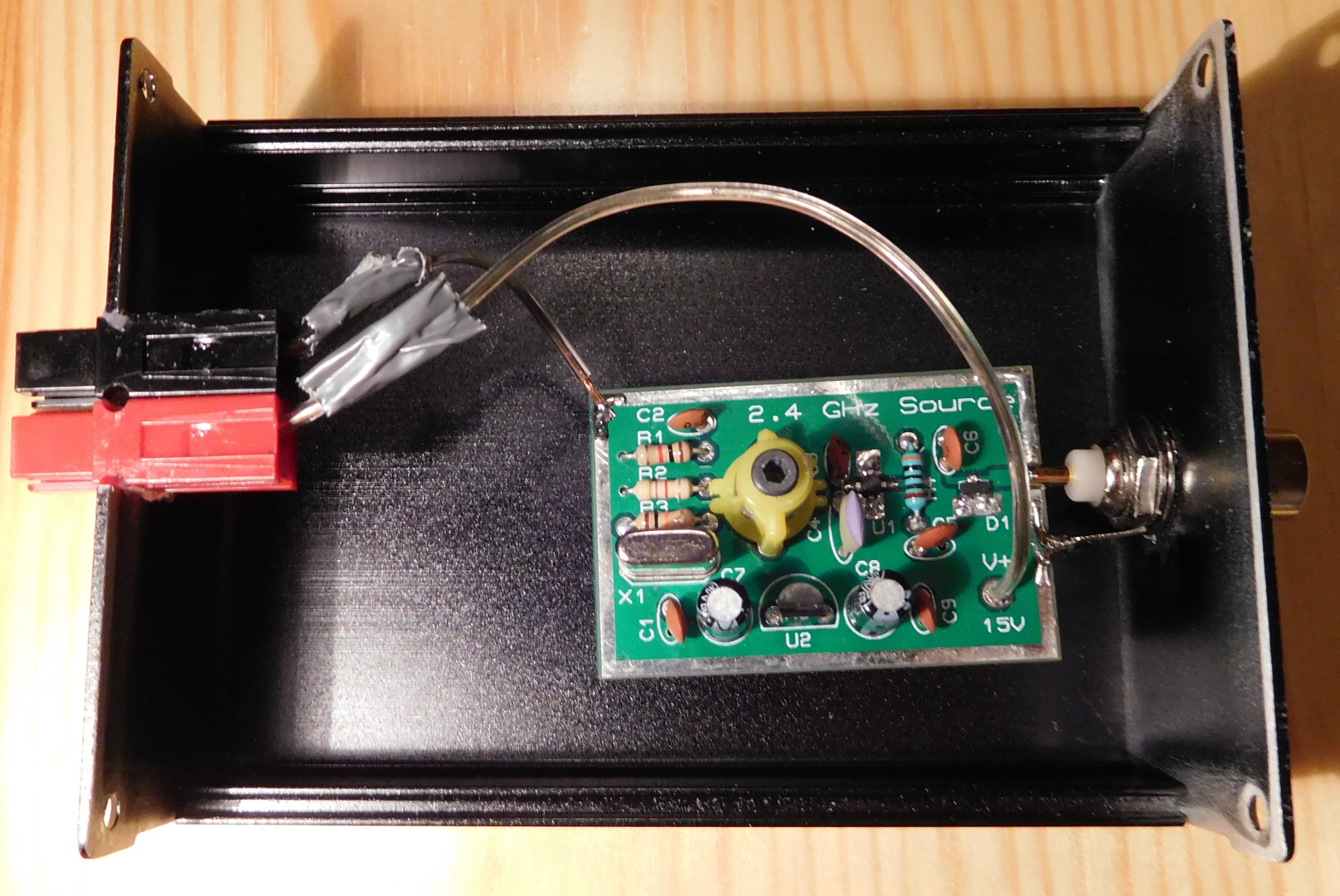
The PCB has been installed in an extruded aluminium enclosure that I got on eBay. Its dimensions are 100x76x35mm and it actually seems to be good quality for its low price. This is a bit large for the small PCB, but the height of the crystal and inductor makes difficult to get a smaller box which is high enough. Since the box is painted, I have sanded off the paint along all the edges to provide good electrical contact between the different pieces.
The output of the PCB is soldered to a BNC connector which is mounted on the front panel. The solder lug on the BNC connector is soldered to the PCB ground-plane with a nice blob of solder that gives some mechanical strength, since this is the only thing holding the PCB in place. A powerpole connector has been used for the supply voltage. To install this on the back panel, I just made two cuts in the panel and bent the tab between them 90º inwards. The connector goes between these two cuts and on top of the tab and is hot glued in place for extra mechanical strength.
please express to me – how do the hatmonic comb generator work
in mixing to get other nixed freqeuncuency to obtain a spefic frequency for a given IF in a receiver or transmitter
harmonic generators are new to me this is the first time i have fave seen for this type of oscillator
I’m not sure if I understand the question correctly. What a comb generator does is to generate a sine (or roughly sinusoidal) wave at a particular fundamental frequency (in this case 96.013MHz). The signal is then processed in a very non-linear fashion (usually amplified and clipped), thus producing lots of harmonics. You get a signal at each integer multiple of the fundamental frequency, extending high into the microwave bands.
Hello Sir,
Would you be able to tell me the component values of your capacitor?
Also,
What is the name/value of your capacitor with ferrite core?
I’ve referenced the schematic off the g0mrf website. It’s a little vague in parts and the kit is no longer sold. I was trying to recreate it by buying parts on my own. Thank you.
Hi Sam,
The capacitor values are listed in the schematic in G0MRF’s webpage. Not sure what else you want to know.
L1 (the thing with the ferrite core) is not a capacitor but an inductor. It’s the S18 https://www.bec.co.uk/downloads/S18%20Series.pdf This variable inductor or another one with a similar range can be used.
capacitors*
I would like to buy some PCBs . Do you have for selling ?
I don’t make these. I only have the one I built as a kit. I think I got it from the AMSAT UK shop. You might want to check to see if they still sell it, or get in touch with G0MRF to ask.
hello , i have a project in which i have to make a comb generator , so i found the scematic that you provided quite helpful but i have a few questions
whats the role of the inductor and how to adjust it ?
du u have simulations of this circuit or at least the harmonics visualised after testing this circcuit ?
Regarding the inductor, this is described in the post. It is the tank for a tuned amplifier, and it should be adjusted for maximum output amplitude in this amplifier. The adjustment is not too critical, though.
I don’t have simulations of the circuit. I checked some of the harmonics with an SDR after building it.
and whats the values of l1 C4 R2 C2 they’re not clear
and finally where is the transistor on the pcb because i didn’t find it ans sorry if i had too many qestions ??
Regarding the transistor Q1, it might be on the back side of the PCB, given that it clearly is not on the front side. It is a surface mount BFS17 in SOT-23 package.
You should do some more research before asking. G0MRF’s page about this comb generator gives a schematic with values for all the components except for the inductor (which is specified as number of turn on a certain core): https://g0mrf.com/source2.htm