The Hardrock-50 HF is a very nice kit for a 50W amateur HF amplifier covering the 160m through 6m bands. It supports interfacing with the FT-817. With the proper cable, the amplifier can be connected to the ACC jack on the FT-817 in order to do PTT keying and read the BAND DATA signal from the FT-817 to select the proper band in the amplifier’s low pass filter automatically. The connections required are shown in the Hardrock-50 Tech Site. Yesterday, I prepared the cable to interface my amplifier to my FT-817ND. However, I have found a problem in my amplifier that prevents automatic band switching from working properly. Apparently, this problem has been fixed in the newest units and can be fixed with an easy modification in the units which are affected.
The BAND DATA signal on the FT-817 works by outputting a voltage according to the band that is selected.
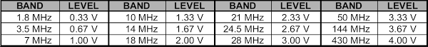
The problem that I have found is that the pin on the amplifier that is to be connected to BAND DATA is pulled up to 5V. This raises the BAND DATA voltage and so the amplifier detects the wrong band. For instance, it will detect 10m when the FT-817ND is on 20m.
When connecting said pin to ground through a 1K resistor, its voltage drops to 0.4V, indicating a 11.5K pull-up resistor (most likely 10K). The BAND DATA voltage, on my FT-817ND on 20m is 1.63V. When connecting the BAND DATA pin to ground through 1K, the voltage drops to 0.215V. Therefore, the output impedance of BAND DATA is about 6.7K on my radio. We see that a 10K pull-up is too strong for this to work properly.
I have emailed Jim WA2EUJ, who is the designer of the Hardrock-50, telling him this problem. He responded quickly saying that he included a pull-up resistor to make the amplifier switch to UNK (unknown band) if the cable gets disconnected. The amplifier being in UNK prevents it keying, so this is a good idea. However he noticed this problem soon and removed the pull-up in newer units. I don’t know why he chose a pull-up value as low as 10K, given the 6.7K output impedance that I’ve measured. Perhaps the output impedance changes widely between different FT-817 units or between the older FT-817 and the newer FT-817ND, and therefore 10K just works fine with some FT-817 units.
Jim says that the pull-up resistor is behind the LCD and it’s very difficult to remove. Fortunately, an easy to access trace can be cut instead. The trace is located on the front panel PCB and shown in the picture below.
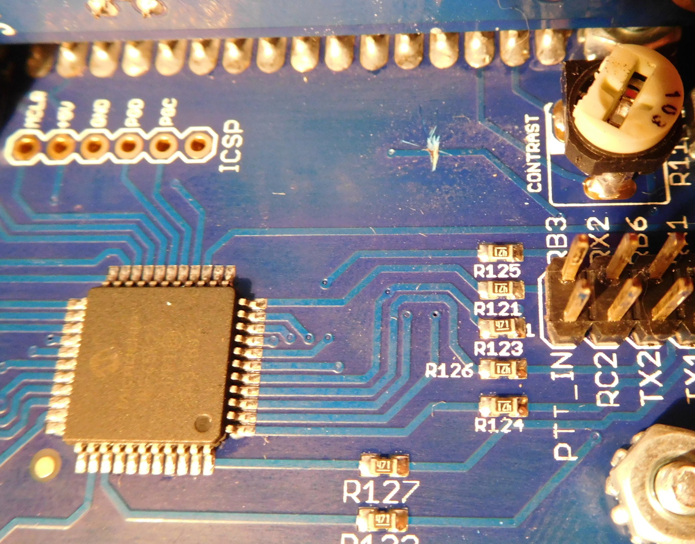
The pin header that can be seen on the right is the 5×2 header where the ribbon cable that goes to the back panel PCB is connected. It is best to remove the ribbon cable before cutting the trace. To connect it back, recall that the cable should be flat between both PCBs, without any twists. If you’re like me and don’t remember how to take apart the amplifier, you just have to remove the screws in the two lower corners of the front panel plate and the two lower corners of the back panel plate. Then the lower cover can be removed. This gives access to most of the hardware inside the amplifier, including the trace that has to be cut.
After this simple modification, automatic band switching is now working on my amplifier as expected.
Thank you for posting this to see band-switching works. I have the newer version of the Hardrock 50 and it worked out of the box. What I wanted to ask is did PTT work with your setup. I could not get PTT to move off of Ground making the amp stay in transmit. I verified PTT is called out as TXGND and it stays low.
Did you see the same issue or can you tell me how your worked.
I didn’t find any problems with the PTT. The TXGND is an open collector output. It is floating when in RX and connected to ground when in TX. You should measure continuity between TXGND and ground instead of voltage. I suggest you test the following: First make sure the Hardrock is in the correct mode. Disconnect your radio completely from the Hardrock. Check that the PTT in the Hardrock is working by connecting the centre pin of the PTT jack and ground. Then check that TXGND in your radio is working by measuring continuity between TXGND (directly at the pin) and ground. If all of this is working then the problem is in your connections, most likely a short between ground and the TXGND line.
I worked out the issue I was having with PTT not working. I could not get consistent results so I got new probes for my DMM. Once I did that I discovered the CAT/Linear drawing on page 7 of the manual was reversed. I confirmed with Yaesu that said the drawing was solder side.
It is good to have the Hardrock 50 working as planned and now off to build the tuner.
Glad you spotted the problem. I hadn’t noted this thing with the drawing before. Probably it’s just because I tend to confuse the orientation even if the drawing is OK, so I usually triple check that I’m doing the right thing.