Since several months ago, I’m operating my HF station “remotely” from another room in the house. The station consists of a Hermes-Lite 2.0 beta2, a Hardrock-50 HF amplifier, and an outdoor MFJ-993BRT antenna tuner. My plan is to operate all of this from a laptop with ethernet connection from anywhere in the house.
The Hermes-Lite poses no problem, since it is always controlled by ethernet only. However, I need to be able to operate the Hardrock amplifier remotely: I need to change the bands, which is usually done via buttons on its front panel, and to check the output power and SWR, if only to be sure that the antenna tuner has found a tuning solution. This is usually done by looking at the Hardrock front panel display or by looking at a Diamond SX20C power/SWR meter that I also have installed in the shack.
I have taken advantage of the holidays to finish making all of this controllable by ethernet. Here I describe my solution.
There are several ways to change the band in the Hardrock amplifier. You can use serial commands (described at the end of the manual), you can use an analogue “band data” control voltage (intended for the FT-817, which has that kind of output), or you can try to control directly the lines that select the filters (see here). The last solution would be the most invasive.
Probably the best solution would be to make the Hermes-Lite control the band of the Hardrock, according to the frequency it is currently set to. The Hermes-Lite is designed to do this by sending I2C commands to a companion filter board. The idea behind this is to control an MCP23008 or MCP23017 in the filter board. The MCP is used to control the relays or PIN diodes in the filter board to select the appropriate band. To simplify the design and gain flexibility, the Hermes-Lite gives raw access to I2C over its network protocol, so ultimately the responsible for setting the band is the software.
I see two possible ways to make this work with the Hardrock: either use a microcontroller (perhaps an Arduino) that listens to I2C commands from the Hermes-Lite and writes the appropriate serial commands to the Hardrock, or design a small board with an MCP23008 that uses some sort of resistor dividers to generate the “band data” analogue control voltage.
I ended up choosing a simpler solution which doesn’t involve the Hermes-Lite. Since I had a BeagleBone black lying around, I decided to use it to control the Hardrock serial interface directly over ethernet. The clear disadvantage of this solution is the cost of the BeagleBone (not a problem for me, since I already had it), but many other cheaper Linux single board computers can be used instead. The advantage is that the BeagleBone could also be used to control many other things in the shack that are impossible to interface directly with the Hermes-Lite alone.
There are two ways of accessing the serial interface of the Hardrock, via USB or via 5V TTL on a DE-9 connector (USB access is done with an MCP2200 USB to UART chip in the Hardrock). At first, I tried connecting the Hardrock to the BeagleBone by USB, but either the MCP2200 or the BeagleBone USB was too noisy. I could see a noticeable increase in the noise floor of the HF bands as received by the Hermes-Lite. Therefore, I decided to connect the 5V TTL serial to an UART in the BeagleBone.
Since the BeagleBone I/O runs at 3.3V, I used a suitable voltage divider to connect the line that transmits from the Hardrock to the BeagleBone. The line that transmits from the BeagleBone to the Hardrock is connected directly (using a resistor in series for protection would be better).
In this way, to control the Hardrock, I just need to ssh into the BeagleBone and then use
picocom -b 38400 /dev/ttyO1
to write to the Hardrock serial by hand. The good thing about this solution is that I also get to see the Hardrock temperature and voltage, since it also reports them on its serial interface.
I have thought of writing a small program to automate this process instead of writing the commands by hand, but I haven’t done it yet, as doing this manually is not a great hassle for me.
However, this solution can’t be used to read the transmit power and SWR. The serial interface of the Hardrock doesn’t work when it’s transmitting (probably for a good reason), so I don’t think that it’s possible to extract this information digitally from the Hardrock (at least without modifying the firmware). However, it is possible to tap into the analogue voltages from the forward and reflected power detectors in the Hardrock. These are designed to give around 2.7V for a measurement of 50W (really, it’s more like 2.7V for 65W).
The Hermes-Lite is designed to be able to use external forward and reflected power detectors in a filter or amplifier companion board. The hardware to do this has changed slightly between different beta revisions, but it essentially involves the MAX11613 ADC to read the voltage from the power detector. The beta2 that I have also has an LMV324 opamp in front of the ADC, as seen in the figure below.
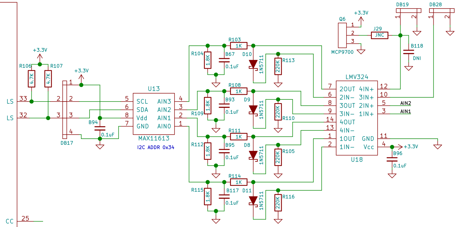
The AIN1 and AIN2 lines go off to a header connector, so these are the lines I’m using to measure forward and reflected power. The other two channels of the ADC are intended for temperature meters in the beta2 (in later revisions one of them is repurposed to measure bias current). Some rather complex circuitry can be installed between the opamp and ADC. The design idea was to try to compensate the diode drop in the power detector by including a diode in the opamp’s feedback path. This idea has been thrown away in later revisions. Here I am just using the opamp as a buffer, so I have fitted D10 and D11 as 0 ohm, R103 and R104 as 1K, B67 and B117 as 0.1uF, and left R104, R113, R115 and R116 unpopulated.
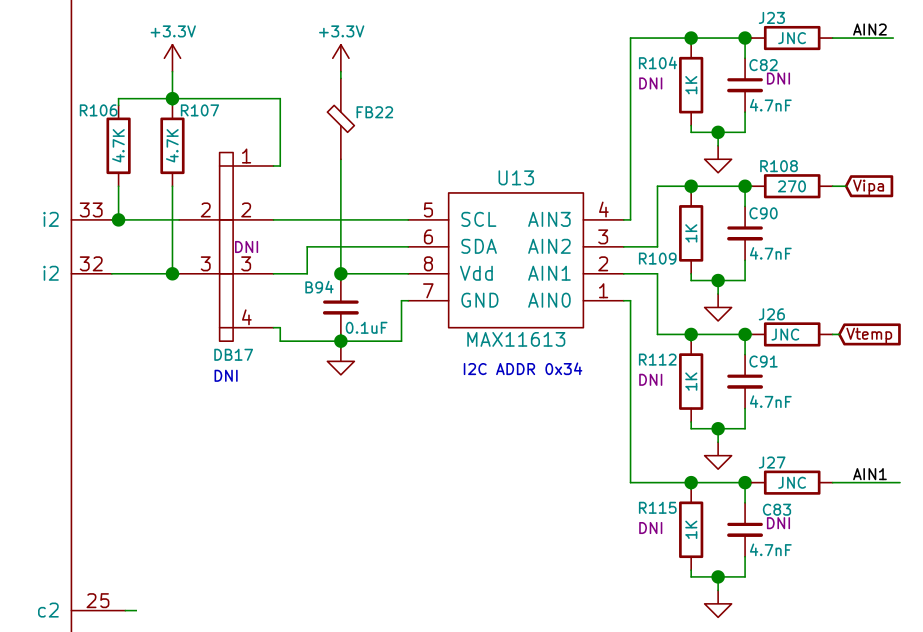
In the current beta5 revision, there is no opamp, and the AIN1 and AIN2 lines go directly into the ADC, so no hardware modifications are needed.
This is all that is needed to make the Hermes-Lite read the Hardrock power detector voltages. However, these voltages are only present internally to the Hardrock, and need to be routed to the Hermes-Lite in some way. I chose to do a hardware modification that is simple and not very invasive.
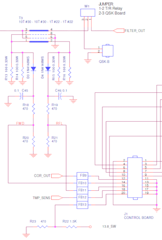
The Hardrock power detectors are shown in the schematic below. They are in the main amplifier board, but the detected voltages then go off to the front panel board via a header. It is easy to tap the voltages off this header.
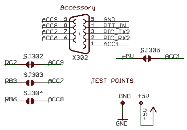
To get the voltages outside of the Hardrock enclosure without drilling new holes, I have taken advantage that some of the pins in the DE-9 connector are left floating. As you can see in the schematic below, there are jumpers in case you want to connect pins 7-9 of the DE-9 connector to the PIC that controls the Hardrock, but these jumpers are open.
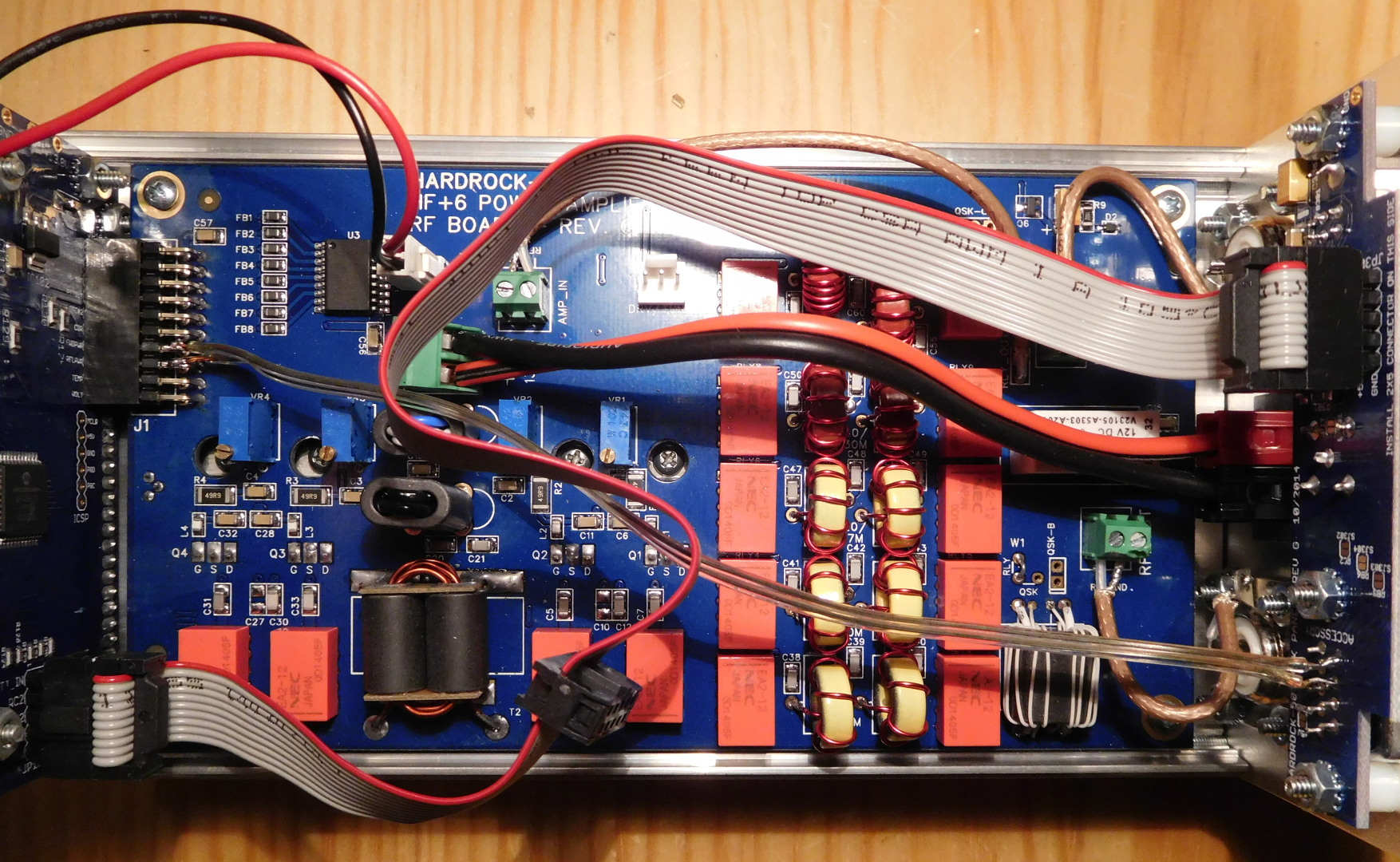
I have decided to use pins 8 and 9 in the DE-9 connector to output the voltages of the power detectors. The modification is simple: just run two wires between the header and the DE-9 pins. It can be seen in the image below. The wire I’ve added is the one with transparent insulation.
The corresponding pins of the DE-9 connector of the Hardrock are then connected to the Hermes-Lite header using wires. This is the hardware aspect of the modification. Now the software must know about it, since the Hermes-Lite reports the raw 16 values from the ADC in its network protocol.
I am using Quisk with my Hermes-Lite 2. The file hermes/quisk_widgets.py must be modified to produce adequate power readings with this setup. The modifications are shown below.
Since the ADC is referenced to the Hermes-Lite 3.3V rail, I have measured the voltage of this rail with a multimeter to get an accurate voltage reading from the ADC. In my case, the rail voltage is 3.256V. This is also used for the temperature sensor. Then, I have adjusted pwr_ref so that Quisk also reports 50W forward power when my Diamond SX20C shows 50W. In my case, this voltage is \(V_o = 2.15\mathrm{V}\). Then, the power in watts can be computed as\[P = 50\frac{V^2}{V_o^2},\]where \(V\) is the voltage measured by the ADC.
Because of the diode drop in the power detector, this measurement is not accurate for low powers (say, below 10W). This could be compensated in software, but I have checked and the Hardrock firmware doesn’t do any software compensation either.
The SWR is computed using the standard formula\[\mathrm{SWR} = \frac{1+\Gamma}{1-\Gamma},\]where \(\Gamma = V_r/V_f\) is the ratio between reflected and forward voltage. Since the raw count from the ADC is proportional to voltage, \(\Gamma\) can also be computed as the ratio between the raw counts of the two ADC channels, as I’m doing here. The SWR is only computed under certain conditions to avoid negative values or division by zero.
The power measured here is “instant” power. It would be easy to modify Quisk to make it measure average power and PEP power, as the Hardrock firmware does. Perhaps I’ll do this in the future.
One comment