Here is a new post in my Artemis I series. EQUULEUS (called EQUL by the DSN) is one of the ten cubesats launched in the Artemis I mission. It is a 6U spacecraft developed by JAXA and University of Tokio. Its mission is to study the Earth’s plasmasphere and to demonstrate low-thrust trajectories in the Earth-Moon region using its water thrusters. The spacecraft communications are supported mainly by the Japanese Usuada Deep Space Center, but JPL’s Deep Space Network also collaborates.
I did an observation of the Orion vehicle and some of the cubesats with two antennas from the Allen Telescope Array some seven hours after launch. As part of this observation, I made a 10 minute recording of the X-band telemetry signal of EQUULEUS as it was in communications with the DSN station at Goldstone. I have published the recording in the Zenodo dataset Recording of Artemis I EQUULEUS with the Allen Telescope Array on 2022-11-16. In this post, I analyze the recording.
Waterfall
I am using the same GNU Radio flowgraph and Jupyter notebook as in the previous posts to compute and plot the waterfall of the recording.
The figure below shows the power spectral density for the X and Y linear polarizations of antenna 1a, as well as their cross-correlation. As in the case of LunaH-Map, we can see a significant power difference between the X and Y channels. This could be either due to the signal being elliptically polarized, rather than circularly polarized, or due to a difference in noise temperature in the X and Y channels, since the gain has been calibrated to have the same noise floor level in both channels. In the case of LunaH-Map the X channel was stronger than the Y, and in the case of EQUULEUS we see the opposite. Since the signals are only 8 MHz apart, it is more likely that what we’re seeing is different elliptical polarizations in the LunaH-Map and EQUULEUS signals, rather than an instrumental effect, because the instrumental effect would be similar for both signals.
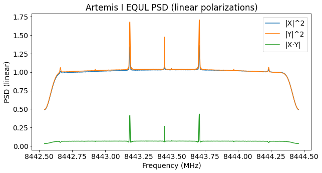
The signal of EQUULEUS is not particularly strong. We see a residual carrier and narrow data sidebands well spaced from the carrier. It is possible to see weak CW carriers at the second harmonic of the subcarrier. We also see the third harmonic of the data sidebands, which contains the same data modulation, rather than being a CW carrier. This is normal for a phase-modulated carrier with a square-wave subcarrier.
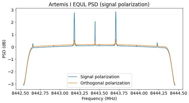
To form the signal polarization, I am ignoring the fact that the signal has different amplitude in the X and Y channels, and only determining and correcting for the phase offset between the X and Y channels. This causes a small fraction of the signal power to leak onto the orthogonal polarization, as we can see in the plot below. Still, the result is good enough to decode the signal using the data from only one of the two antennas.
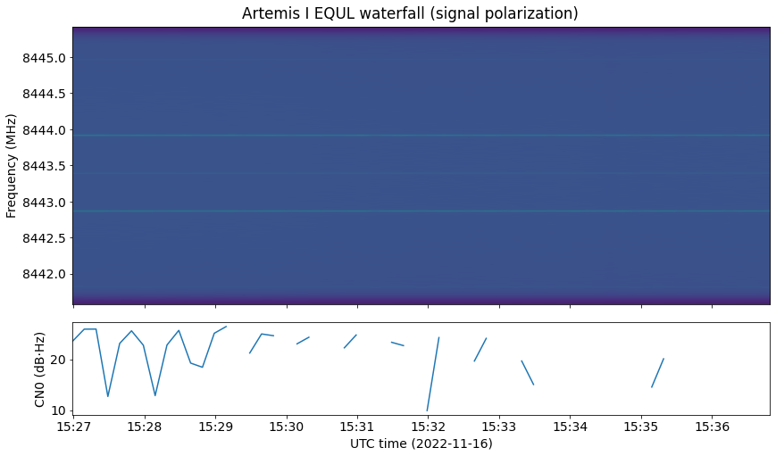
The waterfall is shown below. Note that the CN0 estimation algorithm is giving bad results because it is not intended to be used with such a weak signal (here it is only using the residual carrier).
Modulation and coding
The modulation is PCM/PSK/PM, which means that the data is BPSK modulated onto a subcarrier (which in this case is a square-wave), and the resulting waveform is phase modulated with residual carrier. The subcarrier frequency and the symbol rate are defined in terms of powers of two. The symbol rate is 8192 baud, and the subcarrier is 262.144 kHz, which is 32 times the symbol rate.
The coding is CCSDS concatenated frames. The information frame size is 444 bytes, which is encoded as two interleaved, shortened (254, 222) Reed-Solomon code words. Taking into account the 32-bit ASM and the convolutional encoder, this makes each frame 8192 bits long, so that it takes exactly one second to send a frame.
This scheme of using symbol rates which are a power of two and slightly shortened Reed-Solomon codewords so that the encoded frame length is also a power of two (and so the frame duration is either exactly one second or a second multiplied by a power of two) has also been used by the Chinese spacecraft Tianwen-1 and Chang’e 5. Since EQUULEUS is a Japanese spacecraft, I wonder if there has been some collaboration between Japan and China that has caused this idea to be used by both space agencies.
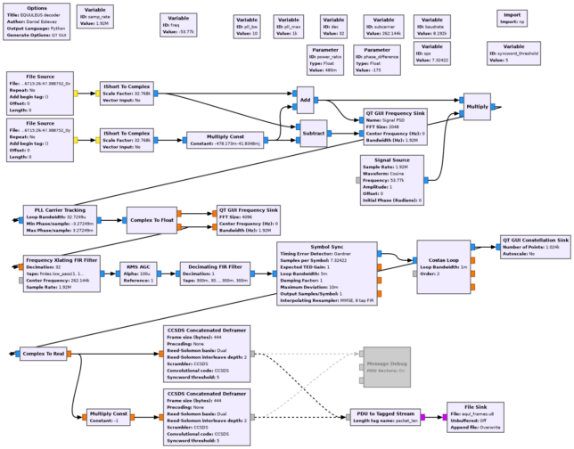
The GNU Radio decoder flowgraph (equl.grc) for this recording is shown below. The X and Y polarization channels are combined using the amplitude and phase corrections determined with the waterfall analysis. Then we have a straightforward demodulator for the PCM/PSK/PM modulation, and the gr-satellites CCSDS Concatenated Deframer block to detect frame boundaries and decode FEC.
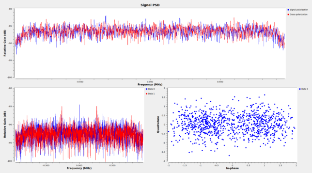
The next figure shows the GUI of the GNU Radio flowgraph while it runs on the recording. We can see that the constellation is not very clean, but still has enough SNR for almost error-free decoding.
Frames
The frames are CCSDS AOS Space Data Link frames. Spacecraft ID 0x50 is used. This is assigned to the EQUULEUS return link in the SANA registry. As in the case of LunaH-Map, the forward link uses a different ID: 0x35C in this case.
Virtual channels 1 and 63 are in use. Virtual channel 1 contains the telemetry data, and virtual channel 63 contains only idle data (which is the purpose for which this channel is reserved). During this recording, virtual channel 63 is only used sparingly. We have 554 frames from virtual channel 1, and 35 frames from virtual channel 63.
The frames in virtual channel 1 contain an Operational Control Field. The contents of this field don’t change during the recording. These are the fields of the corresponding CLCW.
control_word_type = False
clcw_version_number = 0
status_field = 0
cop_in_effect = 1
virtual_channel_identification = 0
rsvd_spare = 0
no_rf_avail = False
no_bit_lock = False
lock_out = False
wait = False
retransmit = False
farm_b_counter = 2
rsvd_spare2 = 0
report_value = 225
In frames from virtual channel 63, the area that would correspond to the Operational Control Field is filled with zeros.
There is no FECF (CRC-16) in the frames. This is normal, because the Reed-Solomon code already provides a relatively good error detection. However, since I’m tuning the decoder for high sensitivity, I’m getting a few false decodes, which most likely correspond to ASM false detections (these would contain almost a correct circular shift of Reed-Solomon codewords if the false ASM detection happens at an offset from a true ASM which is a small multiple of 8 bits). These false decodes are easily discarded because their spacecraft IDs and virtual channel IDs are wrong.
The idle frames in virtual channel 63 always have the virtual channel frame count set to zero. In fact, the idle frames are all identical. I understand that not using the virtual channel frame count in idle frames is a reasonable simplification of the implementation, but it would be nice to have the frame count be used normally, which would allow detecting frame loss on idle data.
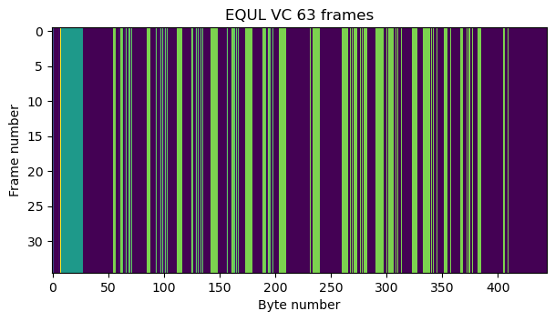
The idle frames contain an M_PDU header with a first header pointer value of 2046, which indicates that there is only idle data in the packet zone. The contents of the packet zone are quite interesting. There are 20 bytes with the value 0x88, and then some kind of pattern formed by the values 0x00, 0x0c, 0xc0 and 0xcc. I don’t know what is the logic behind this pattern. The next figure, which is a raster map of the frames in virtual channel 63, gives a look at this pattern. The green-blue band at the left corresponds to the 0x88 bytes, while the green-yellow bars correspond to 0xc0 and 0xcc bytes.
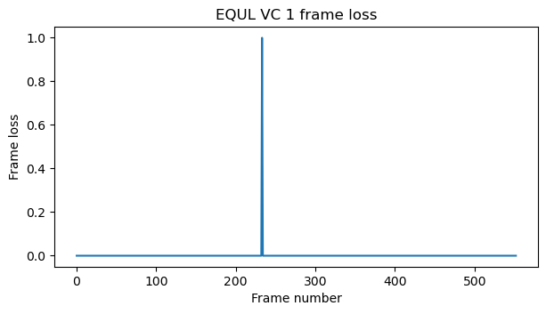
According to the virtual channel frame count field of the frames in virtual channel 1, the decoder has only lost a single frame in the whole recording.
The frames in virtual channel 1 use M_PDU to transmit CCSDS Space Packets. Only APID 1296 is used by these Space Packets, but there are packets of different sizes, which seem to correspond to different packet types (in the sense that they carry different data and have different structure). The most common packet sizes (including the Space Packet Primary Header) are 414 and 420 bytes, and all of the sizes are between 300 and 440 bytes. This is perhaps an attempt to match the frame size approximately, so that it takes about one second to send each Space Packet.
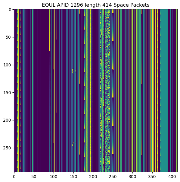
The two figures below show raster maps for the Space Packets of length 414 and 420 respectively. We can see a lot of static data, but some interesting fields that keep changing. I haven’t been able to make sense of what kind of data these have or how is the data encoded. The Jupyter notebook has raster maps for all the packet sizes.
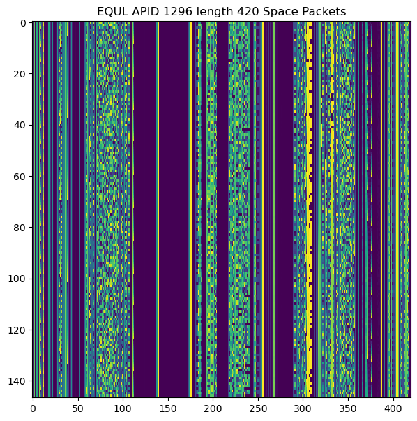
The sequence count field of all the packets is set to zero. The secondary header flag is enabled. It seems that the four bytes following the Space Packet Primary Header are a timestamp in big-endian uint32 format. I have the impression that these timestamps divided by 10 give the number of seconds since the spacecraft was deployed (or a similar event), but I don’t have enough data to confirm this fully.
The difference between the last and first timestamp divided by 10 is 588, and the recording is 592 seconds long. If we interpret the value of the first timestamp divided by 10 as seconds, we get a value of about 4.99 hours. This would place the epoch of the timestamps at 10:27:41 UTC, which was 3 hours, 39 minutes, and 57 seconds after launch.
Code and data
The link to the dataset in Zenodo corresponding to the IQ recording is given at the beginning of the post. The GNU Radio decoder and Jupyter notebook to analyze the frames, as well as the decoded frames, can be found in this repository. The waterfall plots were produced with this notebook.
Hello
Can you please share this on BitBucket, Github or GitLab whichever you can use to cast the net wider.
All the best(73s)
Spencer
@4STTC 🐦
@Spencerx on BitBucket
@Spencerx on Github
@Spence on GitLab
What do you mean? The code is already in a Github repository.