INTEGRAL, the INTErnational Gamma-Ray Astrophysics Laboratory, is a gamma ray space telescope from ESA that was launched in 2002. It is on a highly elliptical Earth orbit, and uses S-band for communications (see this page).
Yesterday, Scott Tilley VE7TIL shared on Twitter a short 30 second recording of the INTEGRAL downlink at 2215 MHz. Since I’ve never had a look at this spacecraft, I decided to try to decode the data. This post is an overview of what I’ve found about the INTEGRAL S-band downlink.
Modulation and coding
The modulation is PCM/PM/bi-phase-L, which means that the telemetry data is Manchester encoded and phase-modulated with a residual carrier. The baudrate I’ve measured in the recording is approximately 262.15 kbaud. This measurement includes Doppler, so the nominal baudrate is probably slightly different.
The coding is CCSDS concatenated coding as described in the TM Synchronization and Channel Coding Blue Book, with a Reed-Solomon interleave depth of 4. The Reed-Solomon encoded frame size is 1020 bytes, so the frames are formed by four interleaved (255, 223) Reed-Solomon codewords. Interestingly, scrambling is not used.
The recording also contains the loopback signal from the telecommand uplink, which uses a subcarrier frequency of 16 kHz and a baudrate of 2 kbaud (this is mentioned in this page). The telecommand signal is idling throughout all the recording.
The GNU Radio decoder for the INTEGRAL downlink can be seen below. The CCSDS Concatenated Deframer block from gr-satellites is used to find the frame boundaries and perform FEC decoding. The rest of the flowgraph is a typical PCM/PM/bi-phase-L demodulator.
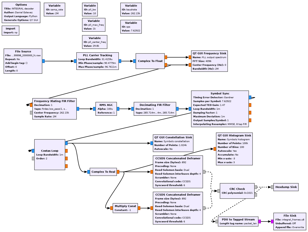
I have taken a lot of care to optimize the parameters of this decoder, because the SNR of the recording is marginal, so unless the loop bandwidths are set quite narrow, we are only able to decode a few frames.
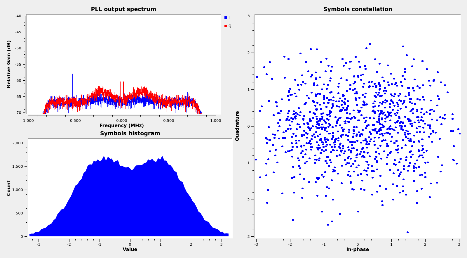
The GUI of the flowgraph running on the recording is shown below. The constellation is so horrible that I have needed to add a histogram plot of the real part of the symbols to see that the demodulator loops are locked. Nevertheless, the decoder is able to obtain approximately 65% of the frames, which I find quite impressive, specially because concatenated coding is not as good as Turbo coding.
TM frames
The frames are CCSDS TM Space Data Link frames as described in the TM Space Data Link Protocol Blue Book. They contain a FECF (frame error control field, CRC-16), which is checked in the GNU Radio flowgraph, so we only get valid frames out of the decoder. The spacecraft ID is 0x79, which matches the SANA registry. The OCF (operational control field) is used, but Secondary Header is not used.
The synchronization flag is set to zero. Interestingly, the segment length identifier field is set to 0b01, although the current Blue Book indicates that the value of this field should be 0b11 whenever the synchronization flag is zero. I haven’t checked historical versions of the Blue Book to see if the value 0b01 was allowed in 2002. The Blue Book indicates that different semantics for this field were used in the past.
Virtual channels 0 and 7 are in use. As we will see below, virtual channel 0 carries telemetry data, and virtual channel 7 carries idle data. Most of the frames are idle. In fact, we have only 25 frames in virtual channel 0, out of a total of 320.
The figure below shows the frame loss using the master channel frame counter in the TM Primary Header. From this we see that between the first and last decoded frame we have missed 35.6% of the frames.

The OCF alternates on every other frame between the OCF corresponding to virtual channel 0 and the OCF corresponding to virtual channel 7 (these are uplink virtual channels, and are, in principle, independent from the downlink virtual channels). The values of each of the two OCF types do not change throughout the recording. They contain the following data:
Container:
    control_word_type = False
    clcw_version_number = 0
    status_field = 0
    cop_in_effect = 1
    virtual_channel_identification = 0
    rsvd_spare = 0
    no_rf_avail = False
    no_bit_lock = False
    lock_out = False
    wait = False
    retransmit = False
    farm_b_counter = 3
    rsvd_spare2 = 0
    report_value = 4

Container:
    control_word_type = False
    clcw_version_number = 0
    status_field = 0
    cop_in_effect = 1
    virtual_channel_identification = 7
    rsvd_spare = 0
    no_rf_avail = False
    no_bit_lock = False
    lock_out = False
    wait = False
    retransmit = False
    farm_b_counter = 2
    rsvd_spare2 = 0
    report_value = 1
Virtual channel 0: telemetry data
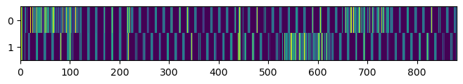
Virtual channel 0 contains telemetry data. The first header pointer in the TM Primary Header is zero in all the frames in this virtual channel. The 880-byte transfer frame data field seems to be divided in two sections of 440 bytes. Each of these sections seems to carry a packet. This can be seen in the raster map below.
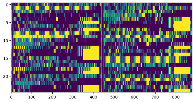
I haven’t found any obvious structures. In particular, the packets don’t seem to be CCSDS Space Packets.
Virtual channel 7: idle frames
Virtual channel 7 contains idle data. The first header pointer in all its frames is set to the value 2046, which indicates idle data. However, this virtual channel is quite interesting. Here we show a raster plot for the transfer frame data field of all the frames in this virtual channel. We can see a pattern that drifts to the left.
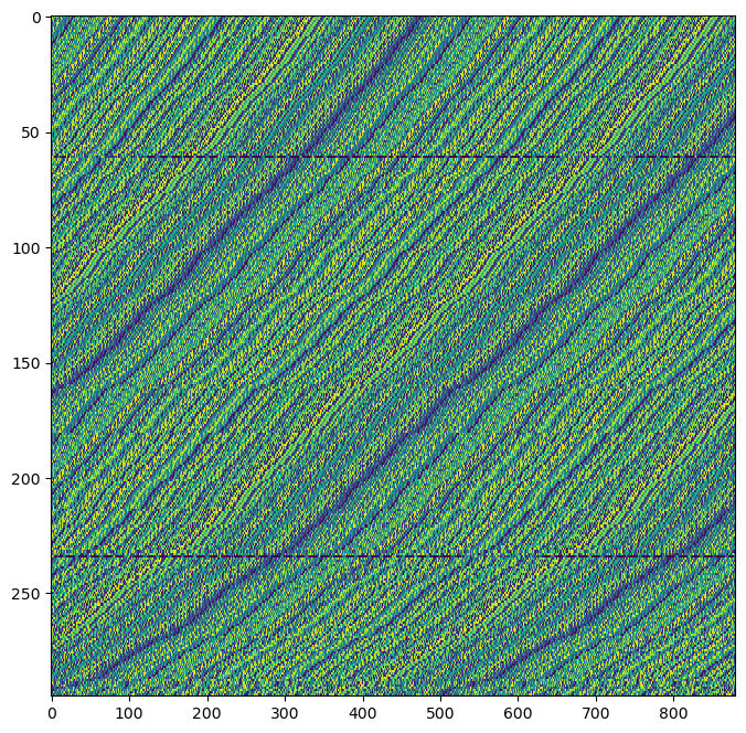
Upon further analysis, it turns out that the contents of the transfer frame data field of the idle frames are generated with a 9-bit LFSR defined by the polynomial \(x^9 + x^5 + 1\). This gives a very typical “PN9 sequence”. It is actually the same sequence that is used by BepiColombo to fill idle frames. It is a good idea to use an LFSR to fill idle frames, and specially in the case of INTEGRAL, because for some reason it doesn’t use a scrambler. Note that since 2021 CCSDS recommends to use a 32-bit LFSR for this (see Annex D in the CCSDS TM Space Data Link Protocol Blue Book).
As we can see on the raster map, the contents of the idle frames keep shifting to the left. This shift can give us some clues about how the LFSR m-sequence is generated on-board the spacecraft.
The transfer frame data field is 880 bytes long, or 7040 bits. This corresponds to 13 repetitions of the 511 bit m-sequence, plus an additional 397 bits. The data field is filled with periodic repetitions of the 511 bit sequence to fill all the 7040 bits. If we measure for each frame the phase of the m-sequence referred to the start of the data field, we find that in general the m-sequence shifts by 16 bits to the left every time that the master channel frame count increases by one. This happens regardless of whether the master channel frame count increases because a frame in virtual channel 0 was transmitted or because a frame in virtual channel 7 was transmitted.
We can also see that occasionally the m-sequence shift by an additional 16 bits to the left in a few particular frames. However, this doesn’t affect the following frames, which continue as if this additional shift hadn’t happened. I have no idea of why this additional phase shift happens.
I think that the reason why, in general, the m-sequence shifts by 16 bits to the left for each transfer frame regardless of the virtual channel that corresponds to that transfer frame is the following. The size of a frame including the Reed-Solomon parity check bytes and the 32-bit ASM is 8192 bits. We have that \(8192 \equiv 16 \mod 511\). This means that if the m-sequence is generated by an LFSR that is stepped for each bit in the transfer frame (including the RS parity and ASM), then for each transfer frame the LFSR would be stepped by an integer number of periods (a multiple of 511) plus an additional 16 steps. Thus, we would find that the m-sequence is shifted 16 bits to the left in the next frame.
Probably this happens because in the spacecraft hardware the bits to be sent to the convolutional encoder and the LFSR use the same clock, and the LFSR steps in every clock edge. This is interesting, because for me it would be more natural to step the LFSR only when we need to consume its ouput. In view of this idea, I don’t have a good explanation for why a few frames include a “transient” additional shift of 16 bits to the left.
There is another unusual aspect about the idle frames. There are two frames that do not fit this description. Their data field does not contain the m-sequence, but rather something else, with a large amount of zeros. Indeed, these two frames can be seen in the raster plot above, as mostly purple thin horizontal lines.
The raster plot below shows the transfer frame data field of these two frames. We can see that their contents are different, but that there are many strings of 8 zeros in both. Moreover, there are many pieces of data that repeat, and it seems that there is a marked 8-byte periodic character.
I have no clue about why this happens and about whether it is intended or it is caused by some unintended (and mostly harmless) design issue. I am confident that these frames have been decoded correctly, because they have a correct CRC-16 and their TM Primary Header looks right.
Code and data
The material for this post can be found in this repository. The GNU Radio flowgraph is integral.grc, and the analysis of the frames and plots has been done in this Jupyter notebook. Refer to Scott’s tweet for the link to the IQ recording.