This is another post about GRCon22’s Capture The Flag (see my previous post). One of the challenges in the Dune track submitted by muad’dib was called Heighliner. It consisted of a short recording of Blockstream Satellite, as we might guess from the challenge description below, especially if we had watched Igor Freire‘s talk about gr-dvbs2rx and Blockstream Satellite (I’ve heard that the fact that the talk and the challenge had the same topic was just a coincidence).
A heighliner just passed through “folded space” and it has sent a secret message to the remaining members of House Atreides on the surface of Arrakis. The communication protocol was historically used for sending visual propaganda films and archival files, recently however, Duke Leto had his engineering guild repurpose the transmission unit for financial transactions. It’s the perfect place for a covert message, the Harkonnens would never think to look there… The original transmission was on Frequency 12.0164GHz. Our groundstation receiver downconverted to 1.2664GHz.
Heighliner challenge description
I didn’t manage to solve this challenge, mainly because I was looking in the wrong place. I was focused on looking at the Bitcoin blockchain chunks, but the flag was in a Blockstream Satellite API message, and I wasn’t aware of the existence of API messages back then. After the CTF ended, a few of us were discussing this challenge in the chat. None of us really understood all the details about how the Blockstream Satellite system works. Since the intended way of solving the challenge was setting up and running the Blockstream Satellite receiver tools, an in-depth understanding wasn’t really necessary.
I have some interest in satellite filecasting systems since I reverse-engineered Outernet back in 2016, so I’ve been taking some time after the CTF to look at the details of how Blockstream Satellite works. While attempting to solve the challenge, I found that detailed enough documentation wasn’t available. There is some high-level documentation, but for the details you need to go to the source code (which is a typical situation).
In this post I describe the details of how Blockstream Satellite works, using the recording from the CTF challenge as an example. I will mainly focus on the Blockstream Satellite API, since I haven’t been able to understand all the details of the Bitcoin blockchain FEC blocks.
Blockstream Satellite is a service that broadcasts the Bitcoin blockchain and some additional related data from GEO satellites. It uses DVB-S2 in Ku-band (and C-band in parts of Asia and the Pacific), and the same kind of transponders and satellites that are used for satellite TV. The figure below shows a coverage map with the satellites and beams that are being used currently.
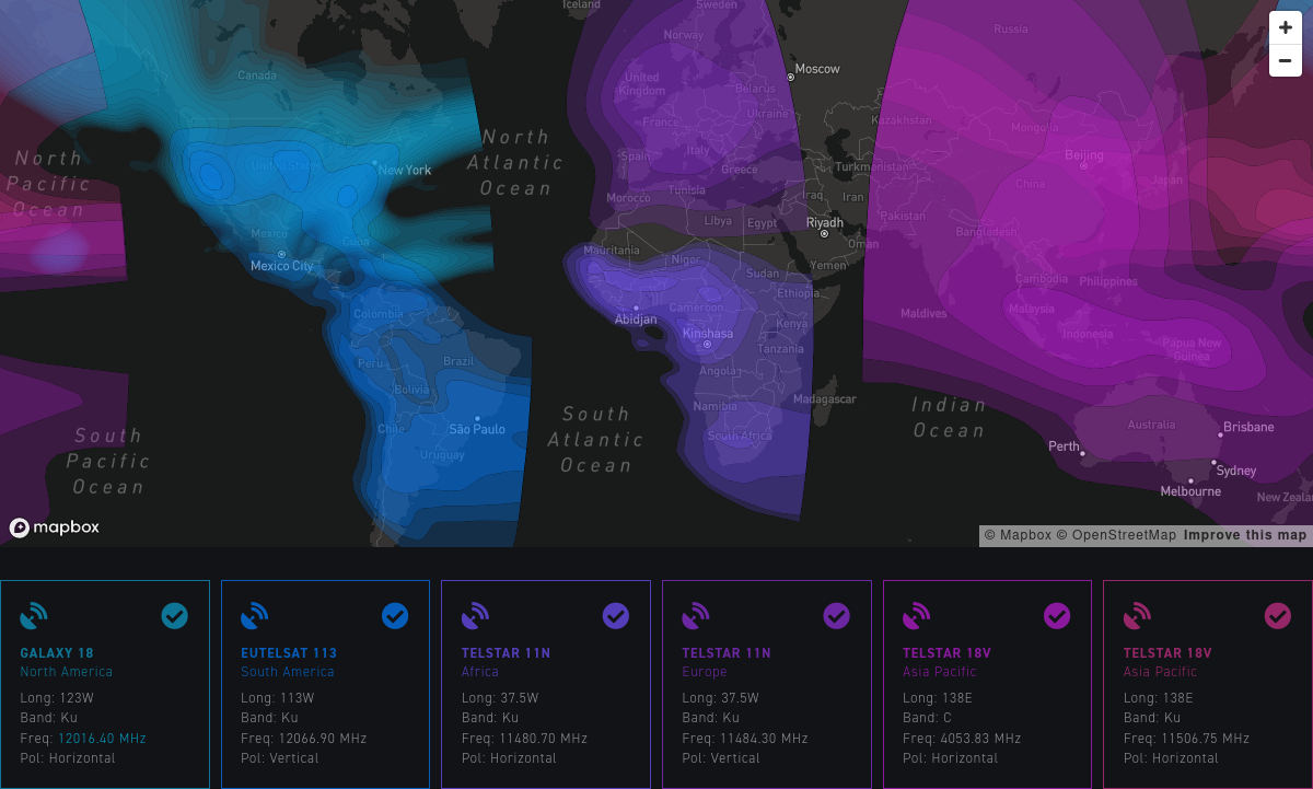
The IQ file for the CTF challenge was a real off-the-air signal recorded from Galaxy 18. There were no tricks and no artificially generated signals. Muad’dib simply paid a few cents to have the flag sent as an API message, and recorded the downlink transmission.
DVB-S2
The signal from Galaxy 13 is broadcast at a frequency of 12016.4 MHz in horizontal polarization. It uses 1 Msym/s DVB-S2 with QPSK 3/5 MODCOD, normal frame size, pilot symbols, and an RRC roll-off factor of 0.2 (see Section 4.3 in ETSI EN 302 307-1 for information about the different settings of DVB-S2). I don’t know if all the satellites use exactly the same configuration.
The CTF recording can be decoded with gr-dvbs2rx and with other DVB-S2 receiver tools, though it’s necessary to be careful, because the SNR is not great, so many tools will have some troubles. I couldn’t manage to synchronize the PLHEADER with the example flowgraph from gr-dvbs2rx, but gr-dvbs2rx comes with a Python tool, also called gr-dvbs2rx, that works better, perhaps because of the loop parameters settings. With this tool, we can run the following to decode the recording and obtain an MPEG transport stream file.
dvbs2-rx --source file \
    --in-file HEIGHLINER_1266400000Hz_2000000sps_75.0dB_2022_09_05_030938.cfile \
    --samp-rate 2e6 --sym-rate 1e6 --rolloff 0.2 \
    --modcod qpsk3/5 --frame-size normal --pilots on \
    --ldpc-iterations 100 \
    --sink file --out-file blockstream.ts
At first the receiver will have some problems trying to synchronize.
log :info: Starting DVB-S2 Rx
vmcircbuf_sysconfig :info: Using gr::vmcircbuf_sysv_shm_factory
ldpc_decoder_cb :info: frame = 0, snr = 5.32, trials = 100 (max)
bch_decoder_bb :info: frame = 0, BCH decoder too many bit errors (FER = 1)
bch_decoder_bb :info: frame = 1, BCH decoder too many bit errors (FER = 1)
bbdeheader_bb :warning: Baseband header crc failed.
bbdeheader_bb :warning: Baseband header crc failed.
bch_decoder_bb :info: frame = 2, BCH decoder too many bit errors (FER = 1)
bch_decoder_bb :info: frame = 3, BCH decoder too many bit errors (FER = 1)
But at some point it will manage to synchronize and continue decoding error-free until the end of the file.
bch_decoder_bb :info: frame = 56, BCH decoder too many bit errors (FER = 1)
bbdeheader_bb :warning: Baseband header crc failed.
bbdeheader_bb :info: Baseband header resynchronizing.
ldpc_decoder_cb :info: frame = 64, snr = 4.90, trials = 7
ldpc_decoder_cb :info: frame = 96, snr = 4.64, trials = 7
ldpc_decoder_cb :info: frame = 128, snr = 4.69, trials = 8
ldpc_decoder_cb :info: frame = 160, snr = 4.56, trials = 8
ldpc_decoder_cb :info: frame = 192, snr = 4.53, trials = 8
ldpc_decoder_cb :info: frame = 224, snr = 4.51, trials = 8
[...]
ldpc_decoder_cb :info: frame = 896, snr = 4.49, trials = 8
log :info: Stopping DVB-S2 Rx
More information about running gr-dvbs2rx for Blockstream Satellite can be seen in this Github issue, which was a huge clue for the CTF challenge.
The recording is 35.57 seconds long, and since it uses complex64 format, it has a size of 543 MiB. The TS file we obtain after decoding is only 4.1 MiB large. The huge difference in sizes is not surprising, since a single QPSK symbol, which carries roughly 6/5 bits of data, corresponds to 128 bits of the IQ recording.
There are 22356 188-byte transport stream packets in the output file. According to this online calculator, this DVB-S2 stream has a net TS rate of 1.161 Mbps. This means that we have decoded 28.96 seconds worth of data. Note that a PLFRAME is 33282 symbols long. We have seen that the decoder has lost 56 frames at the beginning of the recording. That corresponds to 1.86 seconds of lost data. However, the decoder might have also lost a few seconds until it synchronized to the PLHEADER and started counting frames.
Transport stream
Here I have been reusing some of the transport stream analysis Python code that I wrote when looking at Falcon 9 telemetry. There is only a single non-idle PID in the stream, PID 32, and it occupies the TS almost fully. There is only a 0.6% usage of the idle PID 8191.
There is no adaptation field, and the packet header contains the most straightforward values: no transport priority, and no scrambling in the TSC field. The analysis of the continuity counter of the packets from PID 32 shows that no packets have been lost (except for those at the beginning of the recording, before the decoder started producing output data).
Using the PUSI flag in the header and the payload pointer byte we can defragment the payload units corresponding to PID 32.
MPE
PID 32 uses multiprotocol encapsulation (MPE) to carry IP packets. While handling this part of the protocol stack, I have found the documentation about MPE somewhat confusing. Additionally, part of the specification is in ISO/IEC standards, which are behind paywall (but luckily some copies of the standards can be found online). Hopefully this part of the post will serve as an explanation of how MPE works.
The main reference for MPE is ETSI EN 301 192 Section 7. This immediately refers ISO/IEC 13818-1 and 13818-6 (which can be found for free here and here). These ISO standards are very long and it is not immediately clear how they fit with MPE. Luckily, in hindsight most of the relevant information is in the ETSI document.
The payload units we have obtained by defragmenting the TS packets contain a so called datagram_section, perhaps followed by some padding, which consists of 0xff bytes. The structure of the datagram_section is given in Table 3 in the ETSI standard. Below this table, the standard gives an explanation of each of the fields, including references to the ISO/IEC documents where appropriate.
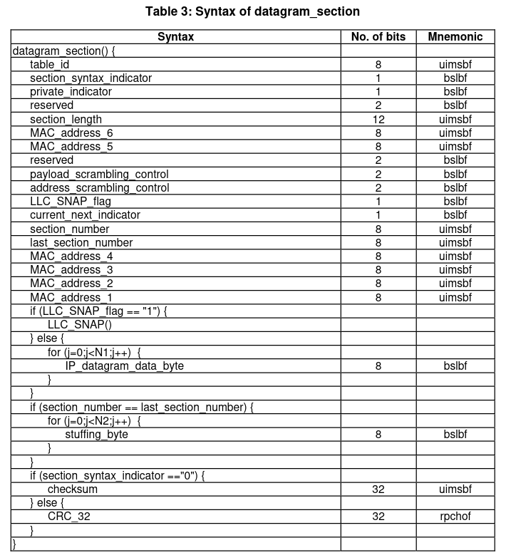
As we can see, the datagram_section contains a header with a few fields describing the format of the section, as well as the MAC address of the receiver. Then there is either an LLC/SNAP frame or an IPv4 packet (or part of them, if fragmentation is used). Then there are some optional stuffing bytes, and finally a CRC, which is either a custom checksum or the CRC32-MPEG.
The table ID field should always be set to the value 0x3e, which indicates “DSM-CC sections with private data”. The section syntax indicator for our MPE stream is 1. This indicates that a standard CRC32-MPEG is used. The private indicator is 0, since according to ISO/IEC 13818-6, this field is “Set to complement of section_syntax_indicator”.
The section length field indicates the number of bytes in the section following this field. Therefore, the total number of bytes in the section is given by this value plus 3. If we compare the length of the section with the length of payload unit that carries it, we see that occasionally the payload unit is longer and there are some 0xff padding bytes after the section. The figure below shows the number of padding bytes used in each datagram section. This is typically zero, but occasionally it spikes up.

Here is a histogram that illustrates better that the usage of these padding bytes is relatively infrequent.
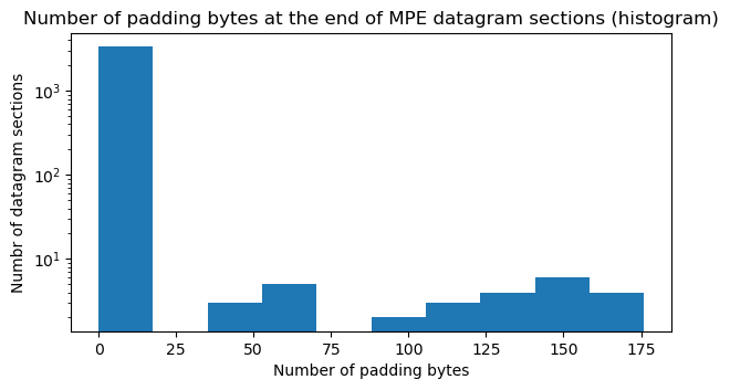
I think that the reason for having these padding bytes is to complete a TS packet so that the end of the section can be transmitted immediately. Otherwise it would be necessary to wait for the next IP packet in the MPE stream to complete the TS packet with the beginning of this packet (note that the size of the padding is always smaller than the 184 bytes of a TS packet payload). This makes sense for a regular network connection, since the next IP packet may not come in quite a while. It doesn’t make so much sense for this type of broadcasting application, where IP packets are transmitted almost without gaps. Nevertheless, I imagine that the MPE encapsulator has some kind of buffer or wait time to try to avoid having to use padding, because we only see padding in 1.5% of the datagram sections.
The MAC address in the datagram section contains the receiver MAC address. In all the datagrams in our MPE stream, the MAC is 01:00:5E:00:00:02. This is the MAC address corresponding to the IPv4 multicast address to which all the IP packets are sent.
In this MPE stream, the payload scrambling control and address scrambling control fields indicate that no scrambling is used. According to the LLC/SNAP flag, regular IPv4 packets are transmitted. Fragmentation is not used, so the section number and last section number fields are zero.
I haven’t understood how the lengths N1 and N2 of the IP datagram part and the stuffing bytes are calculated. I am guessing that these are implicit, since the IP packets contain their length in the header. I am in fact using the total length field in the IPv4 header to find the length of the IP packets. The stuffing bytes would then be any remaining bytes following the IP packet. However, there are no stuffing bytes in this MPE stream.
The usual way of handling the TS output from gr-dvbs2rx is to use tsp from TSDuck to convert the MPE stream into IP packets that get sent to the network. This can be done with
tsp --realtime --buffer-size-mb 1.0 --max-flushed-packets 10 \
    --max-input-packets 10 -P mpe --pid 32 \
    --udp-forward --local-address 127.0.0.1 -O drop
The TS should be written to tsp‘s standard input. This works well for real-time decoding, but if we already have the TS in a file and feed it directly, tsp will choke and drop packets. I found that using pipeviewer (pv) can be useful to throttle the input to tsp.
In my analysis, since I have implemented the processing of MPE in Python, I can use Scapy to parse the IPv4 packets. This has the advantage that we can look at the packets exactly as they were transmitted, since tsp rewrites the local IP address and UDP port.
IP and UDP
All the IPv4 packets are UDP packets sent from address 172.16.235.1 to multicast address 239.0.0.2. There are two UDP ports being used: 4433 and 4434. The source and destination ports of the packets always coincides (stuff to port 4433 is sent from port 4433, and stuff to port 4434 is sent from port 4434).
Port 4434 is used by bitcoind to receive the Bitcoin blockchain. The version of bitcoind used by Blockstream Satellite is a fork of Bitcoin FIBRE, which is a fork of the original Bitcoin Core that adds a protocol to broadcast the blockchain using UDP with application-level (erasure) FEC. My understanding is that Blockstream Satellite introduces some minor modifications to the FIBRE protocol.
I haven’t found very detailed documentation for either the original FIBRE protocol or for the Blockstream Satellite protocol. The best thing seems to be this wiki page, which explains the protocol from a high-level perspective, but doesn’t give the exact format of the packets or the algorithms used for FEC. This page is also potentially useful, as it explains how to run bitcoind with Blockstream Satellite and check that everything is working.
I guess that to gain more understanding of the protocol it’s necessary to go to the source code. There are some files called udpapi.h, udpnet.{cpp,h} and udpmulticasttx.{cpp,h} that seem to contain the implementation of this protocol. I was taking a look at these during the CTF, since I was trying to obtain more information than what I could get from feeding the data to bitcoind. However, I found that the code is not so easy to follow, and didn’t even manage to find how the structure of the UDP packets is defined (specially because it seems that there are several protocol layers).
Port 4433 is used by the Blockstream Satellite API. This system is completely independent of bitcoind and is handled by the blocksatcli Python tool.
Blockstream Satellite API
The handling of UDP packets in blocksatcli is implemented in pkt.py. This is relatively easy to follow, specially if combined with the API documentation.
API UDP packets contains the following fields:
- Packet type / fragmentation. 1 byte. The LSB of this byte is always one, which indicates “packet type = API” and is used as a sanity check to discard packets with the LSB set to zero. The MSB is a “more fragments” flag. It is set to one in all the fragments of a message except for the last one. The remaining bits in this byte seem to be unused and are always zero.
- Channel. 1 byte. Different channels are used to carry different kinds of data. The API documentation gives more information. Channel 1 is the default channel for user transmissions. Channel 4 is used to send Lightning Gossip messages, and channel 5 is used to send the source code for Bitcoin Satellite and Bitcoin Core.
- Fragment number. 2 bytes (big-endian). This is a counter that identifies the different fragments corresponding to the same message.
- Sequence number. 4 bytes (big-endian). The sequence counter is used to identify each message. In this way, fragments for different messages in the same channel can be interleaved, and the receiver can still perform defragmentation.
- Payload. This contains either the full message, if it is small enough, or a fragment of the message. The maximum payload size is 1464 bytes, which comes from an MTU of 1500 bytes, an IPv4 header size of 20 bytes, an UDP header size of 8 bytes, and the fact that the preceding fields take up 8 bytes.
In our MPE stream there are packets in channels 1, 4, and 5. In channel 1 there is a single packet that corresponds to the flag that muad’dib sent. Its sequence number is 10185 and its payload is flag{holder watchmen stilgar} in ASCII.
In channel 4 there are 10 packets that contain fragments 175-184 of a message with sequence number 15413. We don’t have enough data to defragment the full message, but we can see some ASCII text referring to the Gossip protocol, including the string 202209050700.gsp. In channel 5 there are 10 packets that contain fragments 3237-3246 of a message with sequence number 1735. I can’t see any ASCII text in these packets, which makes sense, because the source code would be sent compressed.
Note that the bandwidth allocated to the transmissions in channels 4 and 5 is relatively small. We have collected 10 packets in each channel with a payload size of 1464 bytes over a period of 29 seconds. This gives a bitrate of ~4 kbps for each channel, which is a small fraction of the total ~1.16 Mbps that are available. Most of the bandwidth of the stream is allocated to Bitcoin blockchain data in UDP port 4433.
In addition to sending unencrypted messages, as muad’dib did with the flag, the Blockstream Satellite API also supports sending encrypted data and including application-level FEC. The FEC implementation seems to use zfec. This is one of the FEC libraries that were used in Outernet. It is just a systematic Reed-Solomon code used as erasure FEC. There is an interesting story behind this library, because as I argued in this post, apparently Luigi Rizzo, the original author of the library, independently rediscovered Reed-Solomon codes in 1997 without knowing about them.
In hindsight, it was possible to solve this CTF challenge by grepping for flag{ in the UDP packets generated by tsp (for instance by capturing them to a PCAP file with Wireshark or tcpdump), or almost by grepping in the TS file. The flag was split between two TS packets, but with a little ingenuity it was possible to piece it together. However, I think that no one noticed this during the CTF. The people that solved this challenge did it by running blocksatcli to receive the flag.
Code and data
I have added the code and data that I have used in this blog post to my grcon22-ctf Github repository. This consists of the Jupyter notebook with the Python code to do the protocol analysis, the TS file obtained from gr-dvbs2rx, and a PCAP file with the IP packets.
4 comments