STEREO-A is a solar observation satellite in a heliocentric orbit with a period of 346 days (slightly less than the Earth). It was launched in 2006 together with STEREO-B, which failed 2016. STEREO-A is still operational and producing science data. Whenever the spacecraft is not being tracked by the DSN, its X-band downlink at 8443.530 MHz transmits the so-called space weather beacon. This is a low data rate (~633 bits per second) downlink that contains a summary of the instruments data and that can be received by smaller stations (such as AMSAT-DL’s 20 metre antenna in Bochum, which is one of the stations used to track STEREO-A).
Yesterday, Wei Mingchuan BG2BHC shared some recordings of STEREO-A done with a 13 metre antenna in Harbin Institute of Technology. A large portion of these recordings contains the space weather beacon signal, but there is another part where the transmission first goes carrier only and then transmits wideband data (although the SNR and the recording bandwidth are not enough to work with this signal). Apparently, STEREO-A was being tracked by DSS-35 in Canberra between 7:25 and 10:30 UTC, more or less at the same time that Wei was recording.
In this post I analyse the space weather beacon signal in these recordings.
Modulation and coding
The space weather beacon uses PCM/PM/bi-phase-L modulation. This means that the data is Manchester encoded and residual-carrier phase modulated on the RF carrier. The symbol rate is 3.8 kbaud. The FEC is CCSDS Turbo coding with r=1/6 and 8920 informations bits. From the different FECs described in the TM Synchronization and Channel Coding Blue Book, this is the one that gives the best Eb/N0 performance.
I have quickly put together a GNU Radio decoder flowgraph for the recordings made by Wei. This uses some blocks from gr-satellites and the Turbo decoder block from gr-dslwp (the maint39 branch from my fork of gr-dslwp works both under GNU Radio 3.9 and 3.10).
The flowgraph can be seen running in the figure below. The constellation is quite good, so the Turbo decoder is able to correct all the bit errors.
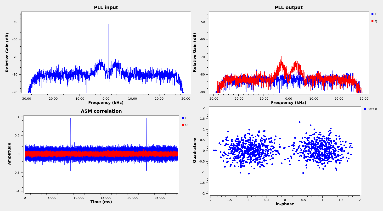
In the long recording there is a frequency jump in the signal caused by a frequency lock or unlock with a groundstation. Taking into account the DSN schedule, it might be the unlock at the end of DSS-35’s tracking. Although not clearly visible in the waterfall below, the modulation is absent for ~37 ms during the jump, which is interesting.

The GNU Radio flowgraph uses a PLL with a bandwidth of 100 Hz. The 10 kHz jump is within the pull-in range of this PLL, so the PLL quickly locks again after the jump, and we only miss the frame affected by the jump.
Data link layer
Wei has published two recordings. The first one is shorter and only contains 40 seconds of space weather beacon data. Since the Turbo frames take up ~14 seconds, there are only two complete frames in this recording. Therefore, I will be loking at the second recording, which is longer and has 22 minutes of beacon data.
The frames are TM Space Data Link frames, with a spacecraft ID of 234 (0xEA). They include a secondary header, an OCF (operational control field), and a FECF (frame error control field, CRC-16). The CRC-16 is checked by the GNU Radio flowgraph. There are two virtual channels in use: 0 and 7. Virtual channel 0 carries idle frames, and virtual channel 7 carries the beacon data.
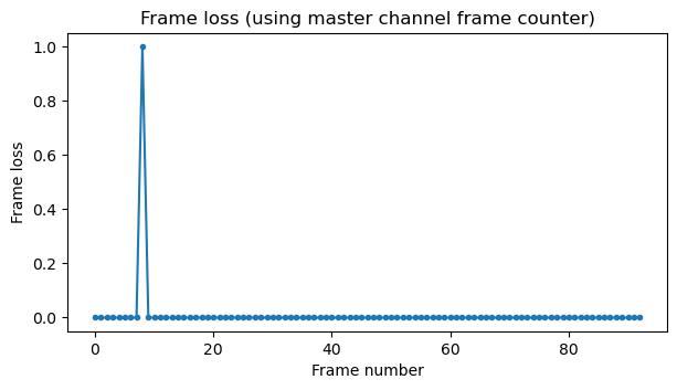
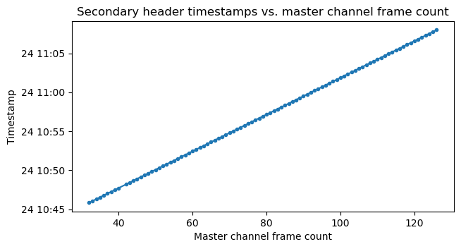
The figure below shows the frame loss calculated using the master channel frame counter. We see that there is only one lost frame. This corresponds to the frequency jump.
The TM secondary header has a size of 15 bytes according to the ID field (the first byte of the header). After the ID field, the first 5 bytes are a timestamp. It is given as a 32-bit integer that counts seconds, followed by an 8-bit integer that counts 1/256-th’s of a second.
According to the filename, the recording was done at 2022-09-24 10:35 UTC. If we subtract from this the value of the first timestamp to try to obtain the epoch, we get 2006-10-25 11:49:50 UTC. This is quite close to 2006-10-25 12:00:00 UTC, which is significant because the launch of STEREO-A was on 2006-10-26 00:52 UTC. Since Julian days start at 12:00, it seems reasonable to make the timestamp be the start of the Julian day in which the spacecraft was launched. The light-time delay for this recording was about 154 seconds, so if the epoch is really 2006-10-25 12:00:00 UTC, then there are around 8 minutes of error in the timestamp. I think that my analysis is correct and that these 8 minutes are due to the drift of the onboard clock.
The remaining 9 bytes of the header are filled with 0x00 bytes for virtual channel 7 frames and with 0xff bytes for virtual channel 0 frames (the pattern used by this spacecraft to fill all sorts of idle data is 0xff). I think that the purpose of these 9 bytes is just to pad the transfer frame data field to a particular size, which will be relevant below.
The figure below shows the TM secondary header as a raster map (each row is one frame, each byte is one column, and the colours indicate the values of the bytes). We can see the timestamps increasing, as well as the 9 extra bytes, whose value depends on the virtual channel.
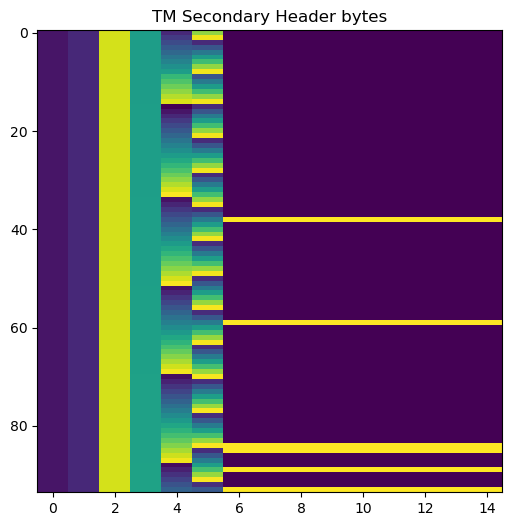
We can see that the timestamps increase steadily with the master channel frame count. The difference between timestamps of consecutive frames matches the duration of a frame as precisely as allowed by the 1/256 second resolution of the timestamps.
The OCF is used to carry a CLCW (communications link control word) as described by the TC Space Data Link Protocol Blue Book Section 4.2. All the frames in the recording carry exactly the same values, which are listed below.
control_word_type = False
clcw_version_number = 0
status_field = 0
cop_in_effect = 1
virtual_channel_identification = 2
rsvd_spare = 0
no_rf_avail = False
no_bit_lock = False
lock_out = False
wait = False
retransmit = False
farm_b_counter = 2
rsvd_spare2 = 0
report_value = 234
It is interesting that the value of the “no RF available” and “no bit lock” fields doesn’t change when the frequency jump happens, since presumably the cause of this jump is a groundstation lock/unlock. This may simply mean that the “no bit lock” field is unused (in which case it should always have the value zero).
I have also looked at the OCF values in the two frames in the shorter recording (which was done about 3 hours earlier). All their values are the same except for the FARM-B counter, whose value is 3 rather than 2. This means that the spacecraft has received some type-B (bypass mode) telecommand frames between both recordings. The number of received frames is congruent with 3 modulo 4, but we cannot say more because the CLCW only contains the 2 LSBs of the counter.
Virtual channel 0: idle frames
Virtual channel 0 is used to send OID (only idle data frames). The first header pointer field in the TM Primary Header is set to 2046, as indicated by the CCSDS standard. The transfer frame data field, as well as the last 9 bytes of the secondary header are filled with 0xff bytes.
Virtual channel 7: space weather beacon data
All the beacon data is sent in virtual channel 7. The contents of all the frames in this virtual channel are shown below as a raster map. We can see that each frame is divided into four pieces of equal length.
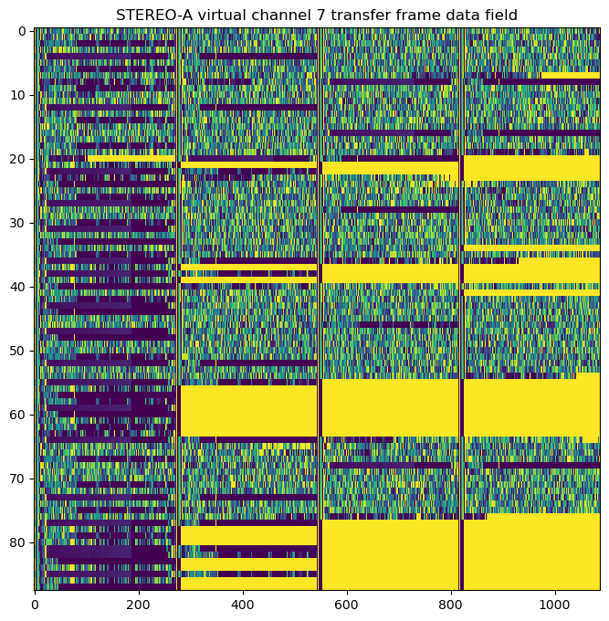
In fact, each frame carries 4 Space Packets of length 272 bytes. This length divides evenly the length of the transfer frame data field. I think that the 9 extra bytes in the TM secondary header are used as padding, however, it is not clear why there is not only 1 padding byte, which would allow making the Space Packets 2 bytes longer. The first header pointer field for the frames in virtual channel 7 is set to zero, since a Space Packet always begins in the first byte of the data field.
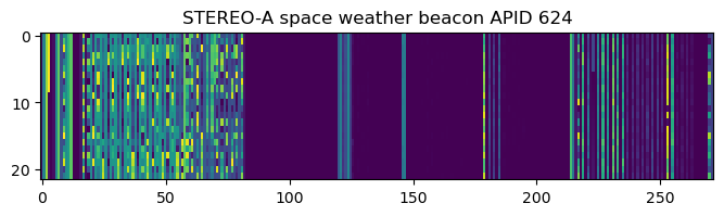
In this recording there are 7 APIDs in use: 0, 624, 880, 1137, 1140, 1393, and 2047 (which is reserved for idle packets). All the APIDs except for 2047 use a secondary header. Raster maps for each of the APIDs are shown below.
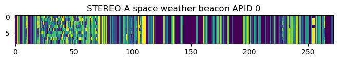
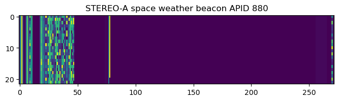
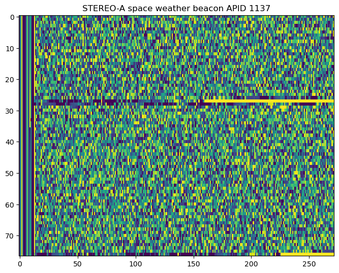
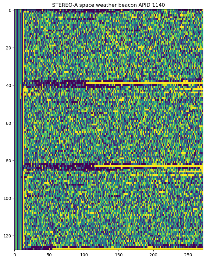
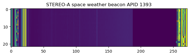
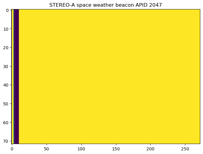
APIDs 1137 and 1140 seem where the bulk of the information is sent. However, they don’t seem so easy to interpret, as there is no obvious structure at first glance (except for the fact that sometimes a string of 0xff bytes is sent as padding). APID 1393 caught my eye immediately. It is analysed in more detail in the next section. The idle packets in APID 2047 are filled with 0xff bytes except for five 0x00 bytes at the beginning of the data field.
The secondary header of the Space Packets seems to be 4 bytes long. These 4 bytes are a a 32-bit timestamp that counts seconds. The epoch is the CCSDS epoch 1958-01-01 00:00:00 TAI (see the Time Code Formats Blue Book). Indeed, subtracting the value of the timestamp of the first packet from 2022-09-24 10:35 yields 1958-01-01 00:05:42, which is close enough to the CCSDS epoch. As in the case of the TM frame timestamps, I believe that the error is caused by the drift of the onboard clock. Note that the error is different, which suggests that there are two independent clocks generating the timestamps.
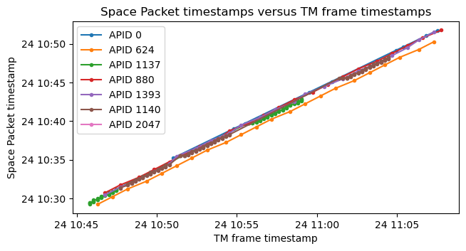
The figure below shows the relation between the Space Packet timestamps and the timestamps on the TM frames that carry these packets, classified by APID. First we note that in general there is an ~15 minute difference between the Space Packet and TM timestamps. I think this is the difference between two independent clocks that have drifted since launch, as I don’t think that there are 15 minutes worth of data queueing up in the transmitter. Another thing we note is that different APIDs seem to have slightly different latencies, as suggested by the fact that their corresponding diagonal lines have different vertical offsets. In this plot we can also note that some APIDs are sent periodically (typically once every minute), while other APIDs are sent in bursts.
The fact that the 5 first bytes of idle packets are zeros, while the rest are 0xff‘s, might hint at the secondary header being 5 bytes long (even though technically speaking these idle packets do not have secondary header). This might suggest that the 5th byte is a 1/256-th second counter as in the TM primary header. However, I don’t think this is the case, as in APID 1393 I’ve been able to meaningfully pair this 5th byte up with the next byte to form a 16-bit integer, while in other APIDs it doesn’t seem possible to do the same. Therefore, I think that the secondary header is 4 bytes long and only contains the timestamp.
S/WAVES beacon data
As I mentioned above, the raster map for APID 1393 immediately caught my eye. This is reproduced here again for convenience.
Some kind of image is apparent in the raster map. There is a gradient that increases from byte ~30 to byte ~190, and some vertical streaks. When I saw this I thought that it seemed like waterfall (spectrum) data of some sort. After reading some documentation about the different instruments carried by STEREO-A and their data products, I am quite confident that we are looking at the S/WAVES data.
S/WAVES is an instrument to study radio and plasma waves (see this paper). It can measure the three components of the electric field in frequencies ranging from a fraction of a Hz to 16 MHz, in addition to a single frequency channel near 30 MHz. The HFR (high frequency receiver) of this instrument can be used to produce spectrum data from 125 kHz to 16.025 MHz in 50 kHz increments. The paper mentions that alternate channels of this spectrometer are sent once per minute in the space weather beacon, giving a frequency resolution of 100 kHz.
Another paper which is worth looking at is STEREO Space Weather and the Space Weather Beacon. This gives an overview of all the data that is included in the beacon, and mentions the same: the S/WAVES data is sent with a frequency of 1 per minute and covers every 100 kHz from 0.125 to 16.025 MHz (this would give 159 frequency channels.
Indeed the timestamps of the Space Packets in this APID are spaced by one minute (2022-09-24 10:30:29, 2022-09-24 10:31:29, etc.). The bytes that seem to form the image are exactly 159: from byte 29 to byte 187 (where we count as byte 0 the first byte of the Space Packet primary header). However, in doing this we need to ignore bytes 26, 27, and 28. These have values which are more or less in the typical range for the waterfall data, but much higher than their neighbours byte 29, 30, etc. So I think that bytes 26 – 28 do not belong to the waterfall. I don’t know what they are. Perhaps some ancillary values from the S/WAVES instrument, though I have seen no mention of this in the literature.
Taking this into account, we can plot the waterfall data with the correct frequency axis and the Space Packet timestamps.
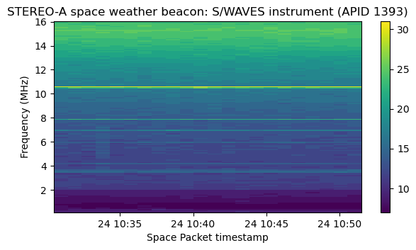
Compare this with the waterfall plot shown in the STEREO space weather beacon webpage. This looks somewhat different because it uses a logarithmic frequency axis, and I think that the data has been weighted to get rid of the increase in power as we go higher up in frequency. Still, I think that we’re looking at the same data. For instance, in the official waterfall there is relatively strong spectral line around 3.5 MHz. This can also be seen in the waterfall I have shown above, though it is not the strongest spectral line. The strongest ones might be too thin for the logarithmic scale to sample them appropriately, as they also are higher up in frequency.
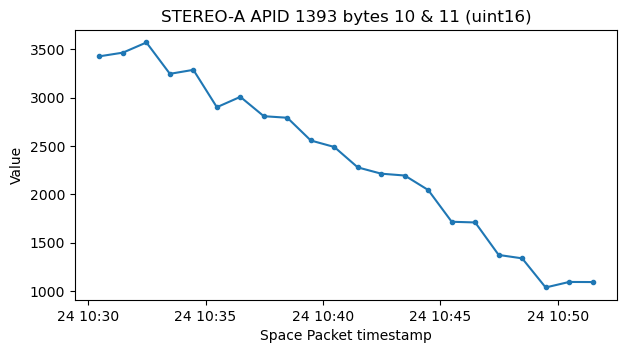
Something else that might be of interest are bytes 10 and 11 in this APID. Together they make sense as a big-endian 16-bit integer. For this recording, the value seems to decrease over time. I don’t know what this is and whether it is related to the S/WAVES instrument or not.
There is also some more data at the end of the packets in APID 1393 that I haven’t managed to interpret. According to the paper about the space weather beacon, there are many different values that are sent every minute. Only APIDs 624, 880 and 1393 are sent once per minute, and APIDs 624 and 880 have large portions of zeros (specially APID 880), so it is likely that APID 1393 carries data from other instruments besides S/WAVES.
Code and data
The code and data used in this post can be found in this repository. The GNU Radio flowgraph is stereo_a_bg2bhc.grc, and the analysis and plots has been done in this Jupyter notebook.
2 comments