DART, the Double Asteroid Redirection Test, is a NASA mission that launched last Wednesday from Vandenberg. The goal of this mission is to crash the spacecraft into the small asteroid Dimorphos, allowing us to measure the small change in the orbit of the asteroid caused by the impact.
From the communications perspective, this spacecraft is the first to use a Spiral Radial Line Slot Array (RLSA) as high-gain antenna. Details about the antenna design can be seen in this paper. The paper shows that antenna polarization is LHCP. Most DSN communications use RHCP, although there are a few notable exceptions (for instance Emirates Mars Mission), and the DSN stations are equipped to handle both polarizations. I’m not sure if DART is indeed using LHCP or if this is just a matter of the convention in the definition of the polarization used in the paper (there are actually two opposite conventions to define the sense of circular polarization).
A few hours after launch, as the spacecraft passed over Europe, Miguel CT1BYM and Iban EB3FRN recorded the X-band telemetry signal from DART at 8421.79 MHz. This post is a first analysis of the signal.
The modulation used by DART in these recordings is 600 kbaud PCM/PM/NRZ, which means that the carrier is directly phase-modulated with the baseband NRZ data. Turbo rate coding with r=1/6 and 8920 information bits is used, so the data rate is approximately 100 kbps. Initially in the mission, a lower rate of 2 kbps was used, since the smaller antennas such as the 4.5 metre in New Norcia weren’t able to receive reliably the higher rate signal.
The GNU Radio flowgraph I’m using to decode the signal can be seen in the figure below. It is very similar to other flowgraphs I’ve been showing in recent posts, such as the one I’m using for Lucy. The flowgraph can be found here.
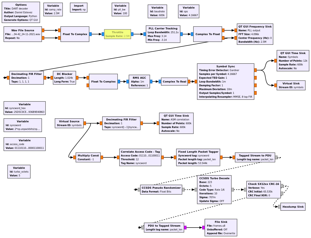
The GUI of the flowgraph can be seen below running on one of the recordings done by Iban. The signal is rather weak, and the data modulation is below the noise floor. However, the correlations with the 192-bit ASM show up clearly, and the Turbo decoder is able to decode correctly some of the frames. A 16-bit CRC is used to filter out only correctly decoded frames.
At this SNR I think that the clock recovery loop is not doing a good job. One of the challenging aspects of low rate Turbo coding is that r=1/6 Turbo coding can work down to approximately -0.25 dB Eb/N0. At that level, the Es/N0 is -8 dB, so the clock recovery loop will have a hard time. I think that an open loop approach at clock recovery, using the ASM correlations will work better. However I think there aren’t yet ready made tools to do this in GNU Radio.
The recording that Miguel made had somewhat better SNR. Unfortunately, his recording was losing blocks of samples from the SDR, so no frames can be decoded. Iban made two recordings of 5 minutes and 10 minutes starting at 08:24:50 and 08:34:42 UTC on 2021-11-24. I could decode a total of 438 frames from these recordings. The decoded frames can be found here. Since frames take approximately 90 ms to transmit, this corresponds to 39.23 seconds worth of decoded data, which is 4.36% of the total number of frames in the recordings.
The frames are CCSDS TM Space Data Link frames. Handling these has been a nice change from all the latest spacecraft I’ve been working with, which use the AOS Space Data Link protocol instead. There are two virtual channels in use: virtual channel 0, which contains Only Idle Data, and virtual channel 7, which contains the telemetry. The frames have a TM Secondary Header and an Operational Control Field.
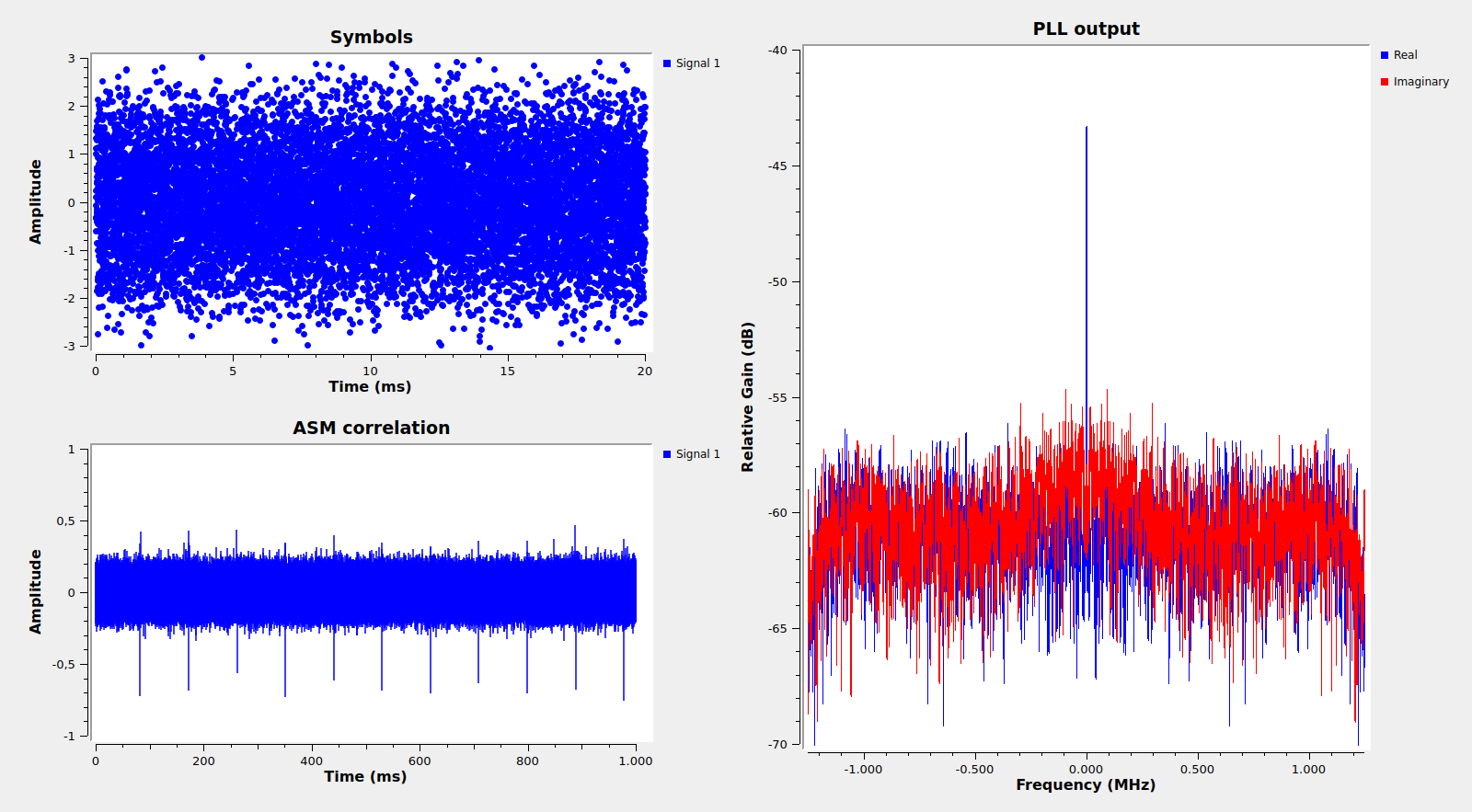
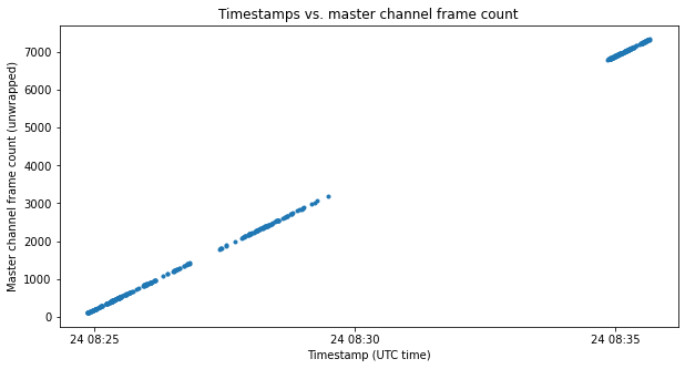
The figure below shows the master channel frame count in the received frames. This has been unwrapped with the help of the timestamps in the secondary header (described below). The large jump corresponds to the gap between the two recordings.
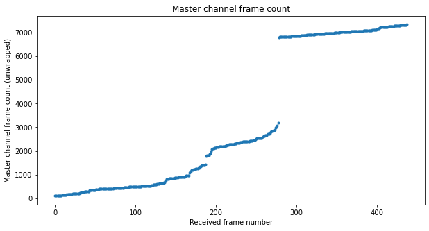
We see that the frame loss is not at all uniform. There are certain moments where many more frames are lost.
The TM Secondary Header has a size of 8 bytes. The first byte is the transfer frame secondary header ID field. The second byte is always 0x34. I don’t know what this field encodes. The last 6 bytes contain a 48-bit timestamp as the number of units of \(2^{-16}\) seconds elapsed since 2010-01-01 00:00:00 UTC. Here we can see the evolution of the timestamps and the master channel frame count. Even though the second recording lasts 10 minutes, the signal level drops significantly after the first few minutes, so there are no decoded frames afterwards.
The Operational Control Field contains a Communications Link Control Word as described in the TC Space Data Link Protocol Blue Book. Its contents do not change throughout these recordings. They are listed below. They show that the spacecraft’s uplink receiver is correctly locked.
control_word_type = False
clcw_version_number = 0
status_field = 0
cop_in_effect = 1
virtual_channel_identification = 5
rsvd_spare = 0
no_rf_avail = False
no_bit_lock = False
lock_out = False
wait = False
retransmit = False
farm_b_counter = 2
rsvd_spare2 = 0
report_value = 0
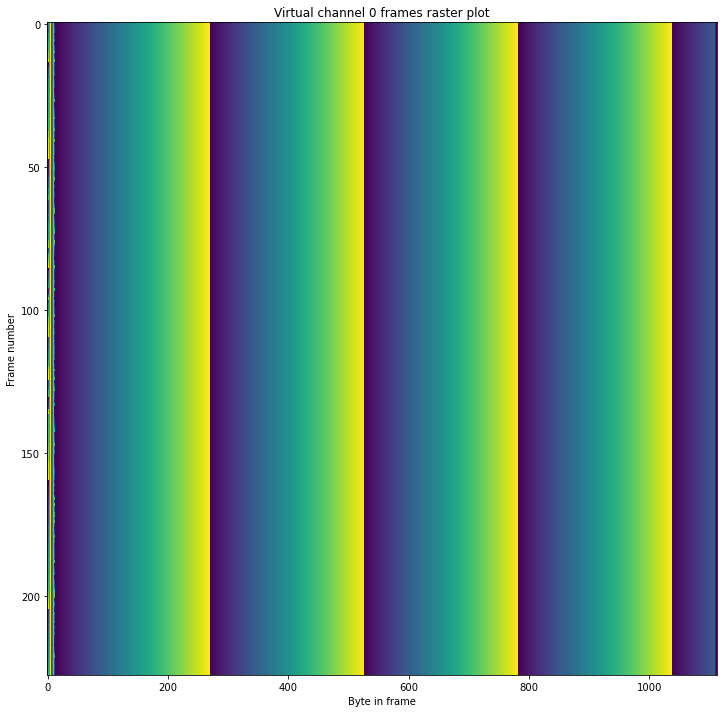
Virtual channel 0 contains Only Idle Frames. The transfer frame data field of these is filled with an 8-bit counter. This counter wraps 4 times during each frame, and is reset at the beginning of each frame. The figure below shows a raster plot of the frames in this virtual channel. We can see the counter increasing and wrapping from left to right.
Virtual channel 7 contains the telemetry data. The raster plot of its frames is shown here.

The first header pointer field in the TM Primary Headers is used to indicate the beginning of the first packet within the transfer frame data field of each frame. Interestingly, the packets are not CCSDS Space Packets, since when trying to interpret as Space Packet Primary Headers the beginnings of these frames, the values we obtain don’t make sense.
It seems that the beginning of each frame contains a counter or timestamp. For the first packets, the first 4 bytes are always 0x1660bbd3, but then this value keeps increasing in later packets. I don’t know how the length of each packet can be determined, since there is no obvious field at the start of the packet indicating it.
I have used a heuristic algorithm to extract the packets. I maintain a 4 byte counter that starts at 0x1660bbd3. For each frame, I start at the position indicated by the first header pointer and then search after this point for either the current value of the counter or an increased version of it (and there is a limit to how much it can increase). If one of these is found, the new increased value of this counter is committed for the next packets, and we try to search the next packet in this frame. If none is found, there are no further packets we can extract from this frame and we continue with the next frame.
This algorithm misses packets that are fragmented across several frames, but since we are missing lots of frames, it wouldn’t be possible to recover most of these anyway. The rest of the packets are successfully recovered without a previous knowledge of their lengths.
We see that there are several different lengths that can appear. Classifying the packets by their length, we note that the packets with the same length have similar contents, so probably they are the same packet type.
The most common packets have length 64. These are shown in the raster map below.
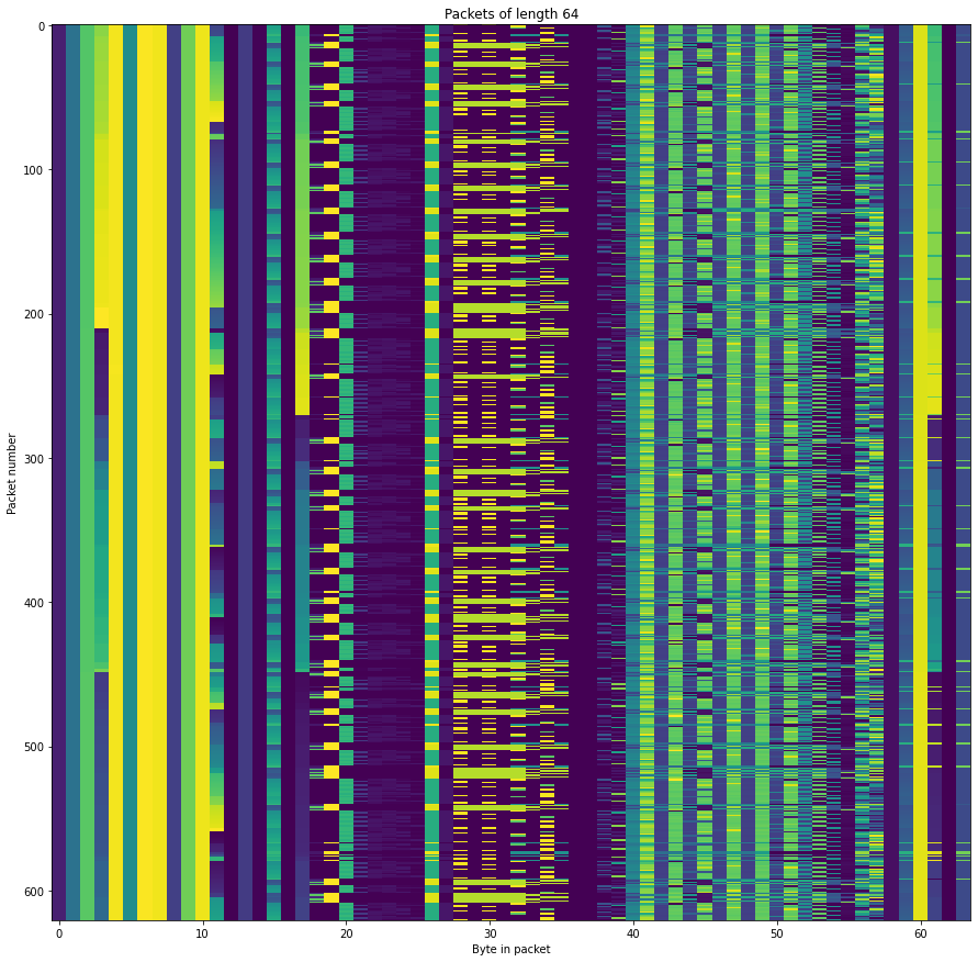
I haven’t spotted anything that looks very interesting. The data for each of the packet sizes doesn’t vary much with time. The plots for all the packets can be found in the Jupyter notebook.