One of the interesting Amateur cubesats in yesterday’s SpaceX Transporter-1 launch from Cape Canaveral is IDEASSat, a 3U cubesat from the National Central University of the Republic of China (Taiwan) designed to study ionospheric plasma. Jan van Gils PE0SAT drew my attention to this satellite as he was trying to see if it was possible to decode it with any of the decoders existing in gr-satellites. Mike Rupprecht DK3WN also helped with a good recording, much cleaner than the SatNOGS recording that Jan was using.
Presumably this satellite uses “AX25, 9k6, GMSK”, as listed at the bottom of this page from Taiwan’s National Space Organization, and also in this research paper. However, this is not true. It’s simple to check that the usual 9k6 FSK AX.25 decoders aren’t able to decode this signal, and a look at the FSK symbols shows that there is no scrambler (9k6 AX.25 uses the G3RUH scrambler) and that the symbol sequence doesn’t have much to do with AX.25.
After some reverse-enginnering, yesterday I figured out how the coding used by IDEASSat worked, and today I added a decoder to gr-satellites to help Mike investigate what kind of telemetry the packets contain. The protocol is not very good, so I think it’s interesting to document it in detail, as some sort of lessons learned. In this post I’ll do so. As it turns out, the protocol has some elements that loosely resemble AX.25, so I’m left wondering whether this is some unsuccessful attempt at implementing standard AX.25 (we’ve already seen very weird attempts, such as ESEO).
An excerpt of the recording that Mike sent me can be found as ideassat.wav in my satellite-recordings repo. From the recording, which is already FM-demodulated, it is clear that the modulation is 9k6 FSK.
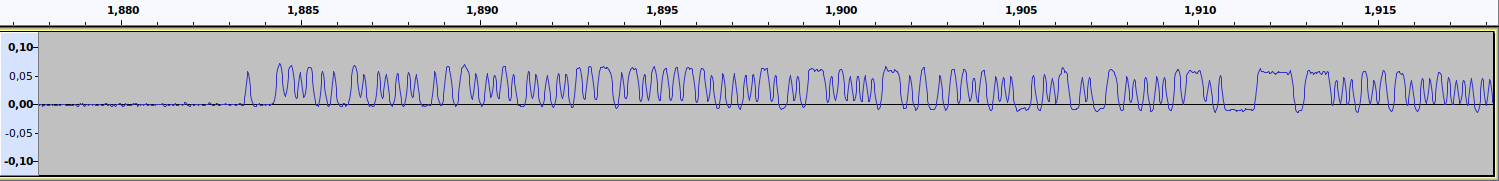
The first thing that shocked me when looking at Mike’s recording is that there doesn’t seem to be any preamble. The packet starts directly with the data, as shown here. This is very bad, because closed-loop clock recovery algorithms need a preamble to lock to the symbol clock.
There is another bad thing about the FSK burst. If we look at the full burst, we see that before and after the burst there is a part that starts negative and slowly decays exponentially to zero.
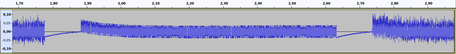
This is caused by the fact that the FSK low tone is held for some 100ms before and after the FSK burst. Doing this at the beginning of the burst is a bad idea. Most FSK demodulators are AC coupled. Even the digital ones, as they use this to correct for frequency errors. So if one of the FSK tones is held for a significant amount of time, AC coupling will drive this tone to zero (just as we see with Mike’s recording). Thus, when the FSK burst starts, it will do so with a large DC offset, as we can see in the first figure.
In any case, all these problems can be sorted out (at least for manual inspection) by using a DC block in GNU Radio to correct for the DC offset at the beginning of the burst and Mike Ossman’s whole packet clock recovery script to extract all the symbols in the burst regardless of the lack of preamble.
After looking at the symbols for a while with NumPy, I realized that they were NRZ-I encoded UART-like data. By NRZ-I I mean the usual differential encoding from AX.25, where a 0 is encoded as a symbol change and a 1 is encoded as no symbol change. I say UART-like because it is exactly like 8-bit UART with one stop bit and no parity (1N8 for short) except for the fact that bytes are transmitted most-significant-bit first, whereas most UART transmit bytes in least-significant-bit first ordering.
The clues that lead me to this conclusion are the following:
- Differential decoding yields a richer autocorrelation than if we don’t do differential decoding; it’s always handy to see how differential decoding changes the autocorrelation
- After differential decoding, the autocorrelation showed peaks every 10 bits, and much larger peaks every 400 bits (which I’ll explain later)
- Arranging the symbols in 10 bit segments, there were two adjacent bits that had constant and opposite values; these strongly suggest the stop and start bits of UART
- The fact that the start bit of UART must be zero and the stop bit must be one indicates NRZ-I rather than plain differential decoding (the two are related by a bitwise inversion)
- When interpreting the UART bytes as most-significant-bit first, I got ASCII data
When decoded as NRZ-I 1N8 MSB UART, I got the following data in hex. The line breaks are mine for clarity and I’ve corrected a few obvious bit errors at the beginning by hand.
7e424e3043552030424e3049444130f000f4b2420741c3d042787fffdf021520000000000101007e
7e424e3043552030424e3049444130f001000101030401ffff07800720071807800728071800007e
7e424e3043552030424e3049444130f0020300670b0b0000000000000000089b04810cb8044b0d7e
7e424e3043552030424e3049444130f003b7035a032101a80cd802800cb80058176800080778007e
7e424e3043552030424e3049444130f00408071800080710fbf81fe000181fe001802f100000007e
7e424e3043552030424e3049444130f005000000000004f800004230424d46554e0000000000007e
7e424e3043552030424e3049444130f0060000000000000000000000000000000000000e6a00ba7e
7e424e3043552030424e3049444130f00707d0ff230c76f483d9cef5c2d4f0ad3047025d8100007e
7e424e3043552030424e3049444130f008271000002b14f81cf51afd00000000000000000000007e
We see that the burst consists of 18 frames which are delimited by 0x7e at the beginning and end. These resemble the HDLC flags. However, there aren’t any other aspects of HDLC such as bit stuffing or the CRC-16. In fact, there doesn’t seem to be any CRC that can be used to discard frames with bit errors. Frames have 40 bytes, and begin in the same way, which explains the strong autocorrelation at lags of 400 bits and multiples (recall that with 1N8 UART we have 10 bits per byte).
Now, the beginning of the frames is ASCII for
BN0CU 0BN0IDA0
These are almost like the AX.25 destination and source addresses (with a SSID of 0) that occur at the beginning of the AX.25 header. However, in standard AX.25 these should be written in the 7 MSBs of each byte (so they don’t look like ASCII text), whereas in IDEASSat these are written in the 7 LSBs of each byte. I’ve encountered this misunderstanding about AX.25 address fields in other occasions.
After the two “addresses”, we have the byte f0, which probably is the PID field with the No Layer 3 protocol value. However, the control field byte, which in standard AX.25 is placed between the addresses and the PID, would be missing.
After the “PID field” we have 23 bytes of what seems to be telemetry. We don’t have a description for the telemetry format. However, it seems that the first of these 23 bytes is a counter that counts from 0 to 8 and iterates through 9 different telemetry structures. Most of the telemetry values seem simple 8-bit signed channels, and structure number 5 contains the ASCII string B0BMFUN. In this example burst, each of the two repetitions of each telemetry structure contains the same values. Probably this is always the case to increase the reliability.
So how does the IDEASSat gr-satellites deframer work? Well, first off, I don’t think that the protocol used by IDEASSat is very good for transmitting data over RF. In fact it is not robust at all, and bit errors will cause all sorts of problems.
Besides the problem of the lack of preamble, using UART over RF is never a good idea. The state machine that tracks start and stop bits is prone to fall into all sorts of traps because of bit errors (unless a very complicate state machine is used). Incidentally, using UART, with or without NRZ-I, guarantees a bit transition every 10 bits, so at least this is good for clock recovery.
The use of 0x7e to delimit frames can create a problem if that byte appears in the data (or even if it appears as a cause of bit errors). Finally, there is no means to check if decoded packets are corrupt.
I’m sure that with effort it would be possible to create a somewhat smart decoder for this protocol. Whole packet clock recovery could be used to prevent the problems caused by the lack of preamble. After NRZ-I decoding, the bits could be correlated against the expected UART start and stop bits for robust byte synchronization. If we use the fact that frames are 40 bytes long, then frame synchronization can also be made robust by finding several 0x7e bytes (maybe correlating against the 36 0x7e bytes that we know should appear in an 18 frame burst). And finally the bit errors in the UART start and stop bits could be used as a heuristic of how many bit errors there were in the useful data, as a means to discard garbage frames. However, I don’t think it’s worth the effort. In the end, this protocol doesn’t have any FEC, and it is something ad-hoc used by just one satellite.
Therefore, today I decided to write a much simpler deframer for gr-satellites, with the goal of not investing much effort and having quickly something ready that Mike could use to start decoding frames.
The decoder in gr-satellites uses the standard FSK demodulator, which does closed-loop clock recovery with the Symbol sync block. The FSK symbols are NRZ-I decoded and then the sequence 00111111010011111101 is used as a syncword. This corresponds to the UART encoding of 0x7e 0x7e, which is found at the beginning of all the frames in each burst except for the first one (which we are going to lose anyway because of the lack of preamble). That sequence is already 20 bits long, so it’s somewhat respectable as a syncword, specially if we don’t allow any bit errors.
After finding the syncword, we extract the 400 bits following the syncword in a PDU and then run a custom block that performs UART decoding. This is done in the most simple manner ever: since we are already byte aligned, the start and stop bits are thrown without looking at them. The size of 400 bits will give us 40 bytes at the output, which makes the next 0x7e 0x7e appear at the end of the frame (or 0x7e 0xff if this was the last frame in the burst). I figured out this was handy, to detect if the frames ever change from their expected size of 40 bytes.
With all this in place, the gr-satellites decoder is working, but care should be taken when analysing the decoded frames. Since there is no way to check for frame validity, frames with bit errors, and even with complete garbage, will appear in the decoder output. Checking that the beginning of a frame is the expected
424e3043552030424e3049444130f0
can give us some confidence about its correctness.
Update 2021-01-26: after receiving some documentation from the IDEASSat team, we’ve learned that there is in fact a CRC. The CRC algorithm is CRC16_CCITT_FALSE using the nomenclature of this online calculator, and it covers most of the useful payload data in each of the 9 frames. A single CRC in the last frame is computed over the data in all the frames.
As an example of this, if we take the 9 frames shown above and throw away the 0x7e flags, the AX.25 headers, and the byte indicating the frame number, we are left with
f4b2420741c3d042787fffdf02152000000000010100
000101030401ffff0780072007180780072807180000
0300670b0b0000000000000000089b04810cb8044b0d
b7035a032101a80cd802800cb8005817680008077800
08071800080710fbf81fe000181fe001802f10000000
000000000004f800004230424d46554e000000000000
0000000000000000000000000000000000000e6a00ba
07d0ff230c76f483d9cef5c2d4f0ad3047025d810000
271000002b14f81cf51afd0000000000000000000000
The last 11 bytes are zero padding. Immediately before this comes the CRC, which in this case is 0x1afd. The first 4 bytes are a beacon counter and are not protected by the CRC. The remaining of the data shown here (starting with 41c3d0… and ending with …f81cf5) is protected by the CRC.
I am going to improve the gr-satellites decoder by using an idea of Andrey Kopanchuk UZ7HO. The new decoder will sync off the end of the “AX.25 header” of the first frame (using the UART encoding of 4130f000 as a 40 bit syncword), take all the frames following that syncword (using the known fixed size), perform UART decoding, reassemble the CRC protected data and check the CRC.
Many thanks to the IDEASSat team for getting in touch with us.
I’m an experienced amateur satellite operator but have never tried decoding telemetry. What do you recommend for a beginner?
Thank you,
Rick VE7SKY / VE7WF
Hi Rick, both the FUNcube and FOX satellites have user-friendly telemetry decoding software, so maybe those are good options to get started.