Last Sunday 2020-07-19, the first mission of United Arab Emirates to Mars, known as Emirates Mars Mission “Hope probe” launched from Tanegashima, Japan. This probe is expect to reach Mars in approximately 200 days and study its atmosphere over the course of two years. The scientific instruments onboard the probe are a digital camera, an infrared spectrometer, and an ultraviolet spectrometer.
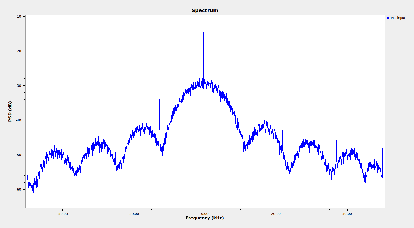
Shortly after launch, several Amateur radio operators and Amateur spacecraft trackers received signals from the X-band beacon of the Hope probe at 8402.655 MHz and posted reports on Twitter, such as Paul Marsh M0EYT, Ferrucio IW1DTU, Edgar Kaiser DF2MZ, and others. Since the spacecraft was still near Earth, its signal was so strong that a data modulation with a main lobe of approximately 20kHz wide and several sidelobes could easily be seen in the spectrum, which is shown below.
Paul has been quite kind to send me a recording that he made with his station on 2019-07-19 at 23:29 UTC and I have been decoding the data in GNU Radio and looking at the frames. The recording can be downloaded here (193MB). It is an int16 IQ recording at 99998 samples per second. This post is an account of my results.
After some analysis, it turns out that the modulation is, using the DSN terminology described here, PCM/PM/NRZ, which means residual carrier phase modulation. The baudrate is 12kbaud and the deviation is approximately 1.29 radians. The coding is CCSDS r=1/6 Turbo frames with an information block length of 1784 bits (so the encoded frames have 10728 symbols plus an ASM of 192 symbols).
The GNU Radio flowgraph I’ve used to decode the frames is shown in the figure below (click on it to view it in full size) and can be downloaded here.
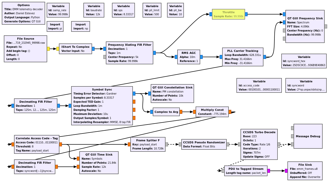
The residual carrier is tracked with a PLL. Since the phase modulation doesn’t have a subcarrier, its power spectral density goes down to the suppressed carrier, so it interferes with it, making carrier tracking more difficult. I’ve used a PLL loop bandwidth of 10 Hz. It also works OK down to 5 Hz or so, but below this it breaks.
I think that 5 Hz is still too much bandwidth for good carrier tracking due to the interference caused by the data modulation. In a real DSN station the receiver clock would be very stable, so maybe a much lower bandwidth can be used, resorting to a higher order loop filter if necessary to model higher order dynamics (such as the line-of-sight acceleration). Additionally, in DSN, the spacecraft’s downlink is often coherently locked to the uplink frequency.
In any case, the PLL carrier recovery with 10Hz bandwidth works OK. After this we do pulse shape filtering and clock recovery. We are at 8.33 samples per symbol, so a square non-matched pulse filter of 8 samples is used before clock recovery, which uses Gardner’s timing error detector. After this, the phase of the symbols is taken and divided by -1/1.29 to yield symbols with an amplitude of one. The minus sign is used here because it turns out that a negative phase deviation corresponds to the symbol one.
I think this is an unconventional approach, as it would be more common to do phase demodulation first and then do pulse filtering and clock recovery. For this high SNR recording my approach works well, but I will have to think more carefully how these two approaches compare in a low SNR situation.
After demodulation, we detect the ASM marking the start of the Turbo codewords and then use the Turbo decoder block in gr-dslwp to perform Turbo decoding. Decoded frames are save to a file for later analysis. The “Correlate Access Code – Tag” can only work with syncwords up to 64 bits long, so we use the last 64 bits of the 192 bit syncword. The OOT module gr-dslwp is originally for GNU Radio 3.7, so I have ported it to GNU Radio 3.8. The port is in the main38 branch of my gr-dslwp fork repository.
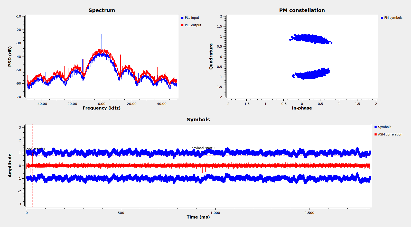
The flowgraph can be seen running in the figure below. The upper left plot shows the spectrum before and after the PLL, the upper right plot shows the constellation at the output of clock recovery, and the lower plot shows the symbols and the correlation with the 192 bit ASM. Two Turbo codewords and their respective ASMs can be seen.
Emirates Mars Mission flowgraph running
The constellation is rather blurry because the PLL tracking has a significant phase error. This can be seen better in the symbols, where both the +1’s and the -1’s seem to drift up and down in parallel. As I mentioned above, I think the receiver clock dynamics are too high to lock a nice constellation in this manner. It should be possible to aid the phase tracking with the phase-modulation symbols, which have more power than the suppressed carrier, even though we would have squaring losses, but I haven’t explored this possibility.
Something interesting can be seen in the correlation with the ASM. There is a positive peak with a normalized amplitude of one, but there are also two negative peaks to its sides with a normalized amplitude of -1/2. This is best seen in the figure below.
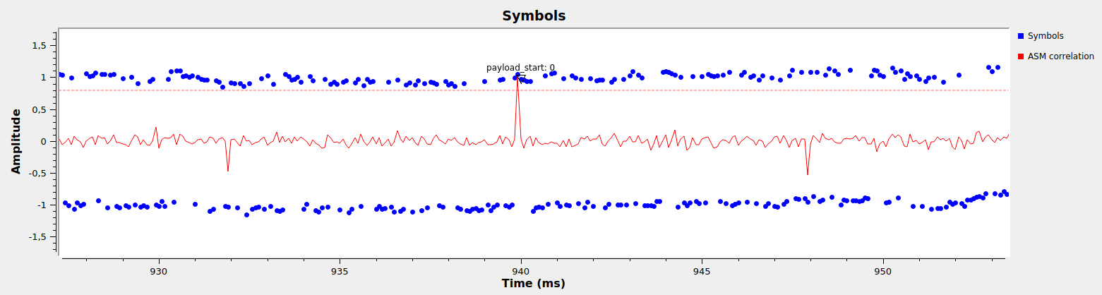
The reason for this is that the ASMs for Turbo codewords of rates 1/4 and 1/6 are formed by concatenating the ASM for rates 1/2 and 1/3 respectively, followed by the inversion of the ASM, in order to obtain an ASM twice as long. This causes a correlation sidelobe of -1/2 at lags equal to plus/minus half the ASM length. For a modulation without polarity ambiguity like phase modulation this causes no problem, since the sidelobes are negative, and we are only looking for a positive correlation. However, for a modulation that has phase ambiguity, such as PSK, we are looking at the complex magnitude of the correlation, and could mistake the sidelobe for the main peak.
This thing we learned in hindsight when writing our paper about the Longjiang-1/2 VHF/UHF communications system with Wei Mingchuan BG2BHC and the other co-authors. The same autocorrelation sidelobes can be seen in the Figure 5 in the paper, and in fact the ASM detector in gr-dslwp could lock onto the sidelobe, so the detection threshold needed to be adjusted to prevent this.
The frames are shown in the figure below. Each 223 byte frame is shown as a row with color-coded bytes. We see that the first bytes are headers of some sort, and the last two bytes are actually a CRC-16 as used in CCSDS Space Data Link TM frames. All the frames have a correct CRC.
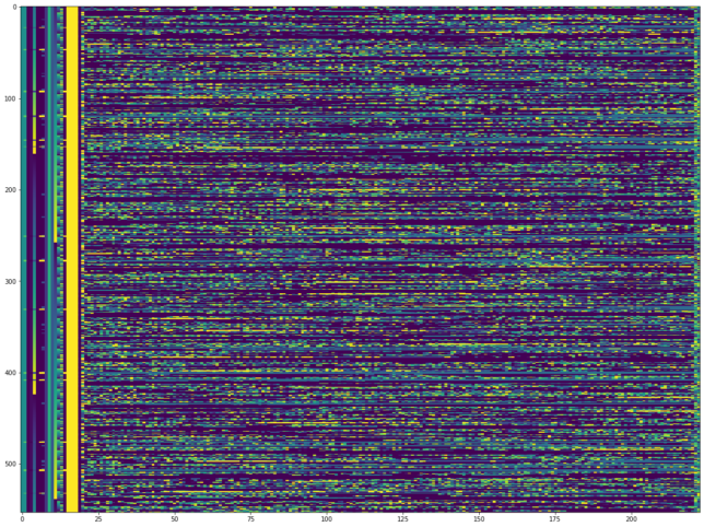
The data can be seen to have structure, so it doesn’t seem to be scrambled any further or encrypted. There are plenty of zeros, and actually some ASCII strings:
$ strings emm_frames.u8 | grep blk
initial_on.blk
launch_comm_cfg.blk
initial_on.blk
launch_comm_cfg.blk
initial_on.blk
launch_comm_cfg.blk
initial_on.blk
launch_comm_cfg.blk
initial_on.blk
adc_miru_bias.blk
initial_on.blk
adc_miru_bias.blk
initial_on.blk
adc_miru_bias.blk
initial_on.blk
adc_miru_bias.blk
initial_on.blk
adc_miru_bias.blk
initial_on.blk
adc_miru_bias.blk
initial_on.blk
as.blk
initial_on.blk
adc_miru_bias.blk
initial_on.blk
adc_miru_bias.blk
initial_on.blk
adc_miru_bias.blk
initial_on.blk
adc_miru_bias.blk
initial_on.blk
adc_miru_bias.blk
initial_on.blk
adc_miru_bias.blk
initial_on.blk
adc_miru_bias.blk
initial_on.blk
adc_miru_bias.blk
initial_on.blk
adc_miru_bias.blk
initial_on.blk
adc_miru_bias.blk
initial_on.blk
adc_miru_bias.blk
Other than this, I haven’t been able to reverse-engineer anything else about the frames payload. I have tried to look for structure around these ASCII strings, but I don’t see anything that makes sense.
The headers on the other hand are quite interesting. They seem to have some similar concepts to the CCSDS TM Primary header, but are also quite different. What follows is some detailed description of the header bytes with the hope that someone may be able to recognise the protocol used.
Byte 0 is always 0x7c.
Byte 1 is either 0x80 (most of the time) or 0xbe (on a few frames). This byte seems to allow us to distinguish between two frame types or virtual channels, which I will call type A and B, since other header bytes and the frame payload differ according to the value of byte 1.
Byte 2 is always zero.
Bytes 3 and 4 seem to form a big-endian 16 bit virtual channel frame counter. This is a counter that increases independently for frames of type A and type B.
Byte 5 is always zero.
Byte 6 is 0x00 for frames of type A and 0xff for frames of type B.
Byte 7 is either 0x00 or 0x40 for frames of type A (I’m not sure what makes it change), and always 0xff for frames of type B.
Bytes 8 and 9 are always 0x26 and 0xa0 respectively.
Bytes 10 and 11 are some sort of big-endian 16 bit master channel frame counter. This is a counter that increases by one with each frame, regardless of type. However, every 10 or 11 frames it doesn’t increase and maintains its value on the next frame.
Bytes 12 and 13 are some sort of big-endian 16 bit “fast counter”. This fast counter increments by 45500 whenever the “master channel frame counter” doesn’t increment and by 61036 whenever the “master channel frame counter” increments by one.
Byte 14 is 0x03 for frames of type A and 0xff for frames of type B.
Bytes 15, 16, 17 and 18 are always 0xff.
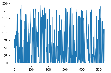
Bytes 19 and 20 can be interpreted as an 11 bit signed field, padded with 5 zeros on the left. Its value for frames of type A is shown below. The only negative number is -1. Its value for frames of type B is always -1. The interpretation of these two bytes is just a guess, but it is somehow apparent that they do not form part of the payload.
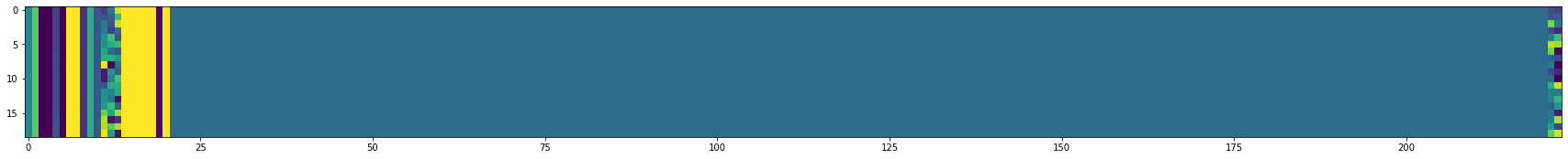
The payload for frames of type B always consists of 200 bytes with the value 0x5a, which is the letter ‘Z’ in ASCII (this may be a coincidence). The figure below shows all the frames of type B. We clearly see the constant payload. In fact, the only bytes that change are the counters in the header, and the CRC.
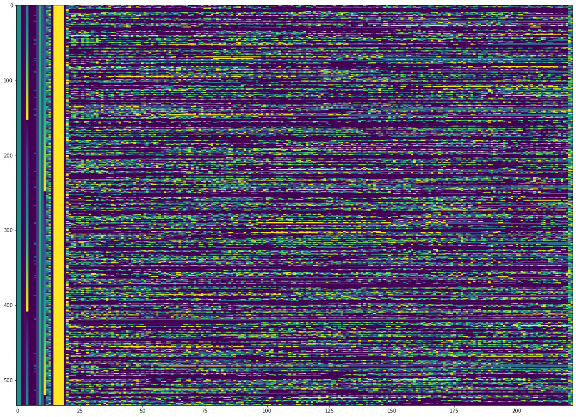
Below we see all the frames of type A. I can even see that bytes 19 and 20 are different from the payload, as we can see that the CRC-16 on the right hand side is also different.
The Jupyter notebook for the analysis of these frames is here. The frames can be downloaded in the file emm_frames.u8 which simply contains the concatenation of all the 223 byte frames in binary.
Fascinating – thank you for working through that!
This isn’t the place for it and it’s certainly not a priority, but I wanted to share on the chance that anyone else ran into the same issue.
FYI, I was not able to compile the ‘maint38’ branch of gr-dslwp on my Ubuntu 18.04 machine with GNU Radio 3.8 (although it runs gr-satellites 3.1.x just fine)
Again, not priority, but if anyone has the same issue and would like to compare CMAKE output, my log and error files are available at:
https://www.dropbox.com/s/6hop767bymcw85c/CMakeError.log?raw=1
-and-
https://www.dropbox.com/s/t1s30jfwh1qesjj/CMakeOutput.log?raw=1
Hi Scott,
Thanks for the report about the maint38 branch of gr-dslwp not building on your machine. I suggest put up an issue with the information, since this maximizes the chances that other may see it if they have the same problem (and will also serve as a reminder to me about it). I’ve seen that the issues were not enabled for that project, but I have just enabled them. You can probably attach the log files directly to the issue.
Bytes 8-13 look like they could be a CUC timestamp with 4 bytes coarse time and 2 bytes fine time i.e. a 48-bit counter with 1LSB=1/65536s. The rate of increase seems reasonable: 10 intervals of 61036 + 1 interval of 45500 corresponds to 10.0076s, and 11 frames of 10728+192 (is that right?) symbols at 12kbaud would take 10.0100s.
However the Epoch would admittedly be a bit funny! It’d be close to J2000 – the coarse time in the first frame is 0x26A04514, and this would map to 2020-07-14 22:27:33, about 5 days earlier than the time of the recording. I wonder if their timer initialisation could have been set up to match a J2000 Epoch near the start of the launch window? This seems to have been 2020-07-14 20:51:27 so the observed coarse time would have been launch+1:36:06, whereas the recording time was launch+ 1:30:46.
Hi Mike,
Thanks for the help. Probably you’re right about the timestamps. When dealing with Tianwen-1 I noticed that the EMM frames are AOS Space Data Link frames, just as Tianwen-1, so by taking this into account perhaps more information can be obtained. I’ll come back to this when I finish with Tianwen-1.
Regarding funny epochs, I think Tianwen-1 also gives a good example of that. It drove us mad for a couple days until we figured it out.