Today I have released gr-satellites v3-alpha4, the fifth alpha in the series that will lead to the refactor of gr-satellites in which I’ve been working since September. This alpha release has been focused on improving the performance of the BPSK and FSK demodulators. Here I summarise the improvements and new features that this alpha brings, and look at the roadmap leading to the release of gr-satellites 3.0.0.
Probably the largest improvement in the demodulators is the usage of the Symbol Sync block for clock recovery. This block fixes some of the bugs in older clock recovery blocks and is more general and powerful. For BPSK I am still using a maximum likelyhood TED with a matched polyphase filter. The correct TED gain has been computed as described in this post. For FSK, I have switched from the Mueller & Müller TED to the Gardner TED. The TED gain has been computed using a Jupyter notebook which is a rewrite of the Matlab simulation written by Andy Walls.
To analyse the performance of the demodulators, I am looking at two things, the BER and the lock-in performance (how fast the demodulator loops will lock at the start of a new packet). For most applications of gr-satellites, the received signals are packet bursts (some with rather short preambles) with moderate or strong SNR. Therefore, weak signal performance is not critical, and some is sacrificed for the sake of a fast lock-in. This means high loop bandwidths that cause too much jitter at low SNR.
All the performance tests for the demodulators are available in the tests folder. The BER simulation is done with ber.py. An LFSR is used to generate a periodic sequence of bits, which are modulated, passed through an AWGN channel, demodulated with the gr-satellites demodulator component, and correlated against the original LFSR to compute the number of bit errors. The script computes and plots the BER depending on Eb/N0.
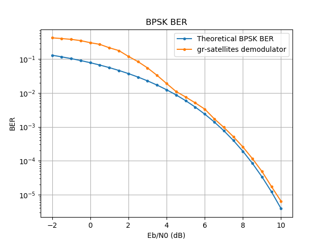
The BER curve for the BPSK demodulator using the default loop parameters can be seen below. There are some large implementation losses for low SNR, mainly due to jitter in the clock recovery and Costas loops. However, for Eb/N0’s greater than 4dB the demodulator follows the theory closely. As remarked above, this is done on purpose to achieve a good balance between fast lock-in and low BER.
The BER curve for the FSK demodulator is much worse than what the theory for non-coherent FSK states. The reason for this is the demodulation algorithm used in gr-satellites: the FSK signal is FM-demodulated using the Quadrature Demodulator block (which approximates the frequency of the signal by computing the phase difference between adjacent samples) and then some filtering and clock recovery is done with the output of this block. This gives suboptimal results.
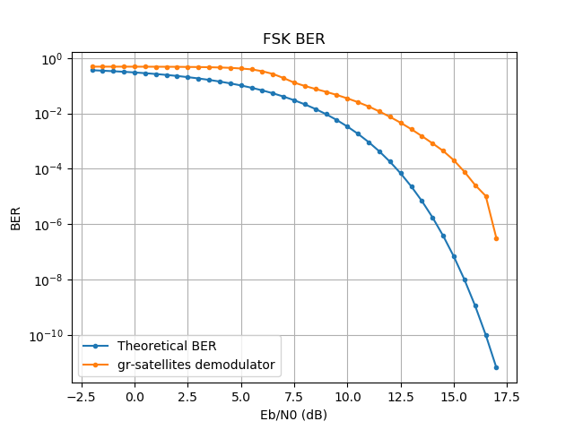
A much better way to demodulate non-coherent FSK is to shift each of the tones to baseband, accumulate coherently for a symbol period, take the power, and compare to see which tone gives the largest power (basically, what is shown by David Rowe here). However, this approach has the disadvantage that the FSK deviation needs to be known or estimated from the signal and that it can’t work with the audio or discriminator output of a conventional FM receiver.
There are still many people using conventional FM radios, and more importantly, most of the recordings of FSK satellites out there are of FM demodulated audio, rather than IQ RF. Also, the deviation of most FSK satellites is unknown and would have to be estimated on the fly or measured for each satellite. Therefore, I have decided to settle on the current demodulator even though it gives worse performance. I might add the other type of demodulator as an option in the future.
In the FSK demodulator, after quadrature demodulation, there is a square (integrate and dump) pulse filter, and a DC block to remove any offset due to frequency error. Then there is an optional AGC to adjust the signal to unit amplitude, and then the Symbol Sync block using the Gardner TED. The AGC is needed if the deviation is not known. It is always on if using a real input signal (which comes from an FM demodulator), since the gain of the FM demodulator is unknown virtually always. It defaults to off if using an IQ signal, since we have control of the gain of the FM demodulator. However, this requires that the deviation is specified correctly (or at least approximately), either in the SatYAML file or with the --deviation command line parameter. Otherwise, the AGC can be enabled with --use_agc.
The lock-in performance of the demodulators is tested with lockin.py. This generates a few short packets and dumps all the internal signals to files, so that they can be analysed and plotted later. The analysis is done in this notebook for BPSK and this notebook for FSK. There you can see how the different demodulator loops lock in at the start of each packet.
I have used this lock-in simulation to find some loop parameters that work well with most of the recordings in satellite-recordings. This is tested in the test.sh script. In some cases, it might be necessary to adjust the parameters slightly to obtain good decodes. For FSK, these parameters are the clock recovery bandwidth --clk_bw and clock recovery frequency error limit --clk_limit. BPSK has in addition the FLL bandwidth --fll_bw, and Costas loop bandwidth --costas_bw. It is also possible to disable the FLL with --disable_fll.
To aid in adjusting the parameters, it is possible to dump the internal signals of the demodulators to files by using the --dump_path parameter, which will create a few files in the indicated path. Then these can be plotted with Numpy.
As an example, let us examine the AU02 recording in satellite-recordings. If we run
gr_satellites AU02 --wavfile ~/satellite-recordings/au02.wav \
    --samp_rate 48e3 --dump_path /tmp/fsk
we don’t get a decode. We can plot the output of the clock recovery with
import numpy as np
import matplotlib.pyplot as plt

x = np.fromfile('/tmp/fsk/clock_recovery_out.f32', dtype = 'float32')
plt.plot(x, '.')
plt.show()
We get the plot below, which shows that the clock recovery has failed, but only slightly. It looks like there is just a clock cycle slip mid-packet.
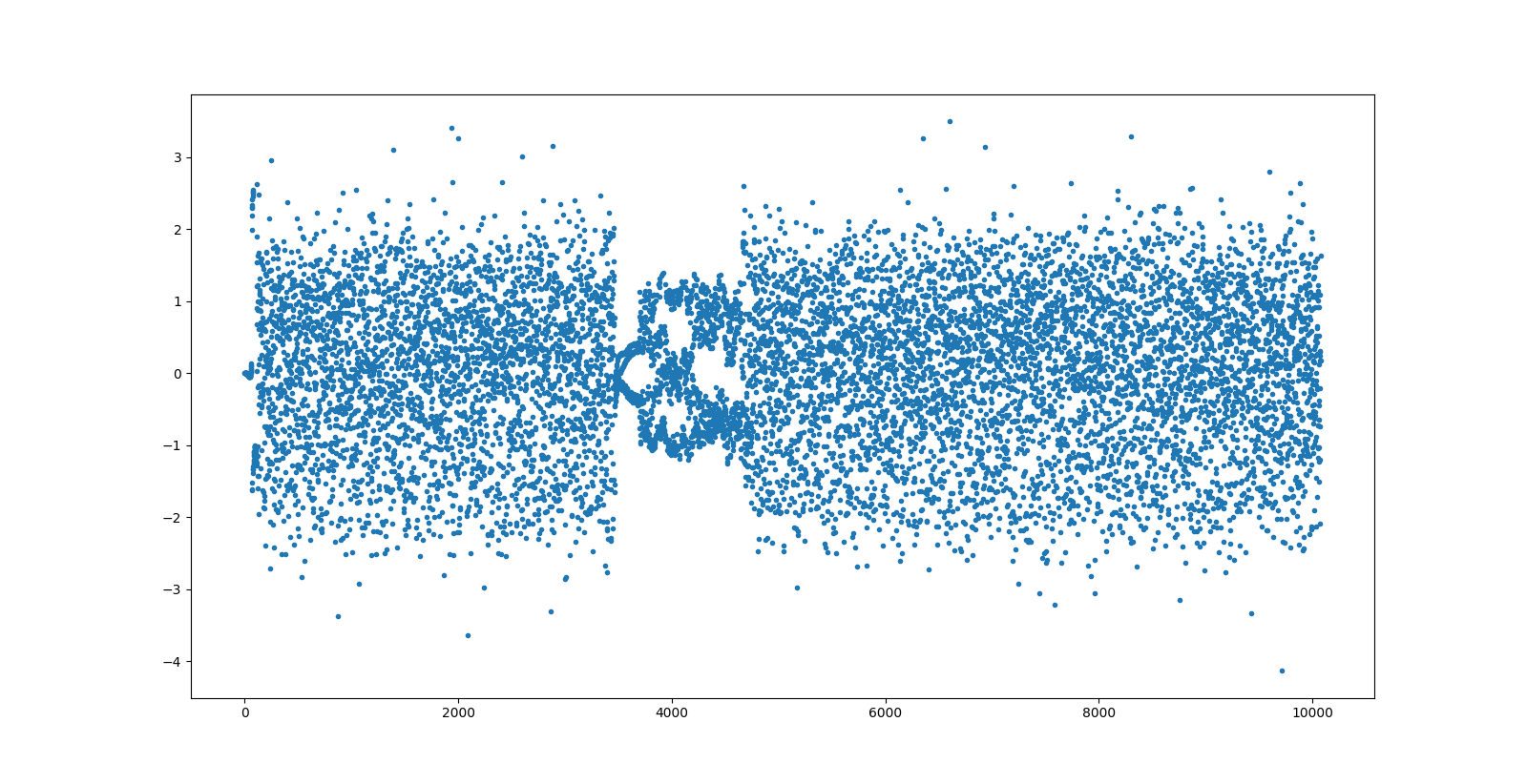
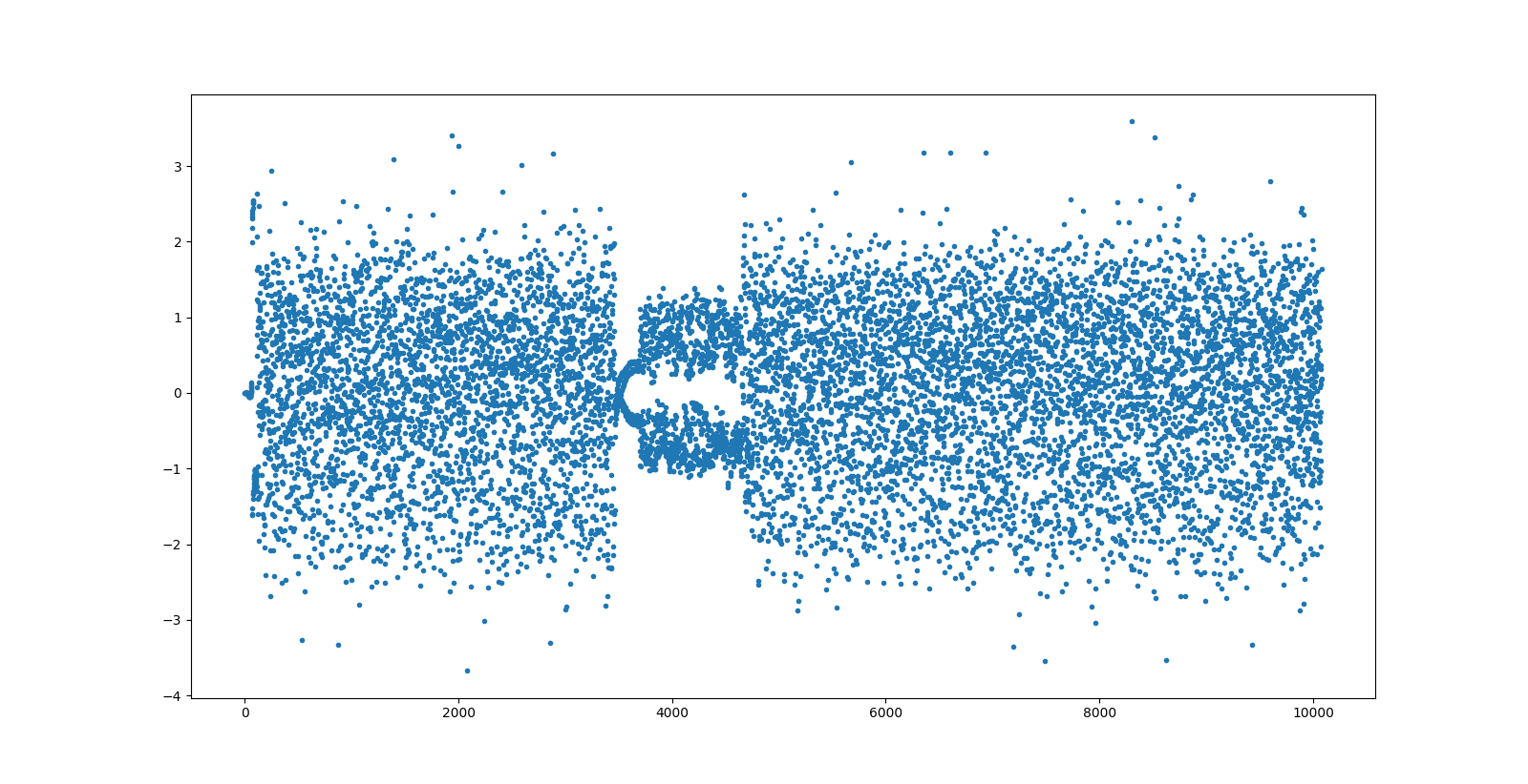
We increase the default clock bandwidth of 0.06 slightly to 0.1 by using --clk_bw 0.1 and then we see a decoded packet. We plot again the output of the clock recovery, seeing that this time the clock recovery has worked correctly and there are probably no bit errors.
With this alpha, the release of gr-satellites 3.0.0 seems now quite near, since almost all the functionality I wanted is already working. In practise, it might still take a month or two until it’s ready for release. Most of the work that still needs to be done is documentation. I want to write some documents explaining the architecture from the perspective of the user (since the amount of blocks and functionality might be overwhelming). Essentially this amounts to rewriting the README file completely (which is already very long) and adding new markdown files. I also want to provide some example flowgraphs showcasing the functionality (intended for people wanting to reuse gr-satellites blocks in their own decoders).
When all this is ready, the next branch will be moved to master, and a v3-beta version will be released. If everything goes well with the beta, it will become v3.0.0, which will be merged into maint-3.8, and the development of the v2.*.* series will stop.
Thank you so much for the updates and detailed explanations!
Regarding the following:
———
For most applications of gr-satellites, the received signals are packet bursts (some with rather short preambles) with moderate or strong SNR. Therefore, weak signal performance is not critical, and some is sacrificed for the sake of a fast lock-in.
———
… would there be any value (or is it even possible) to “auto-scale” the speed of the demodulator loops at a rate proportional to the SNR — to perhaps increase lock-in performance on weaker signals?
Thanks!
-Scott, K4KDR
Hi Scott,
Your idea to adapt the loop bandwidths to the SNR is interesting, and you’re not the first one to think about it. That is indeed a thing in the research literature. For example see this article about adapting loops of a GNSS receiver depending on signal conditions.
For the use case of gr-satellites, however, I think that using that idea successfully would require lots of experimentation and parameter tweaking, and I’m not even certain it would work very well after a lot of effort. The main difficulty is that the packets are short and the signal conditions are ever changing. One packet might be strong, but by the time you’ve noticed that, the packet is already gone, so you set your loop bandwidths hoping a strong signal for the next packet. The next packet might be weak however, due to fading.
A more sensible and far easier approach is to run several copies of the decoder with slightly different parameters in parallel (or sequentially, if processing a recording). This is just limited by computing power. Indeed, it can already be done by writing a script that runs gr_satellites on the same recording with different parameters. Something would be needed to remove the duplicate decodes.
Thank you for the great work!
Can you comment FLL graph:
https://github.com/daniestevez/gr-satellites/blob/eba8517ec92795ed203c98e7d039274fdce10b77/tests/Lock%20in%20BPSK.ipynb
It looks like FLL continue to move frequency even if lock acquired. Am I right?
I noticed strange FLL behavior on a signal with no beacons at the beginning. If no lock at the beginning, then FLL keeps iterating and offset frequency too much. And even if recording contains good beacons in the middle, they cannot be decoded.
I’m wondering if it is better to search FFT max power in that case.
Hi. In that particular graph the test is too short for the FLL to lock completely. This might be seen better in the plot of the PLL phase. The phase keeps increasing, but at a slower rate every time that a packet comes and the FLL moves down in frequency a little bit.
By now I’m not completely convinced about the usefulness of the FLL, at least in all situations, so there is a flag to disable it. The problem is that it’s somewhat slow to converge if the bandwidth is set low enough to avoid significant jitter.
As you say, it also keeps drifting whenever there are no signals (and we often have a few packets and that’s all). If the spectrum of the noise is more or less flat, then it shouldn’t drift too far, but if the spectrum isn’t flat then it can drift significantly.
I think that it’s quite useful for something like the FUNcube beacon, which is a continuous signal. It will lock correctly in frequency in a couple seconds, and then keep track. However for short packets I’m a bit sceptic about its usefulness.
Detecting the max power FFT bin (at least per se, without any other mechanisms) doesn’t seem a good idea, in my opinion. A more reasonable approach would be to detect the syncword by time-frequency correlation and use the detection to initialize the clock phase and PLL frequency.