K2SAT is a cubesat developed by the Aeroespace Systems and Control Lab in KAIST, a university in Daejeon, South Korea. It will be launched later this year, between September and October. The main mission of the satellite is to test the transmission of images taken with its onboard camera using an S-band QPSK transmitter that supports up to 2Mbps data rate. This will use the 2.4GHz Amateur satellite band, and the satellite has already coordinated a downlink frequency of 2404MHz. The K2SAT team at KAIST is the same one that built the QB50 KR01 (LINK) cubesat.
Since February, I have been collaborating with Pilwon Kwak and the rest of the K2SAT team to produce a GNU Radio receiver for the S-band image downlink and add it to my gr-satellites project. This receiver has now been publicly released. Here I explain the main details of the transmitter and protocol used by K2SAT and the implementation of the receiver.
The transmitter used by K2SAT is the STX from Clyde Space. This is a 2.4GHz transmitter that transmits either QPSK or OQPSK at a bitrate of up to 2Mbps (symbol rate up to 1Msps). The coding of the user bitstream in the STX transmitter goes as follows.
The bitstream is first scrambled using the V.35 Intelsat scrambler. This scrambler is also known as the IESS-308 scrambler and I have already spoken about it in my Outernet reverse engineering posts. The implementation for the descrambler in the K2SAT receiver is thus taken directly from gr-outernet.
After scrambling, the data is sent to a differential encoder. The output of the differential encoder goes to a convolutional encoder with \(k=7\), \(r=1/2\), and CCSDS polynomials. The output of the POLYB polynomial is encoded as the I of the QPSK symbol and the output of the POLYA polynomial is encoded as the Q of the QPSK symbol. The QPSK symbol is then transmitted over the air using an optional \(\alpha = 0.35\) RRC filter. Viterbi decoding is done in GNU Radio using the FECAPI CC decoder blocks.
When receiving a QPSK constellation, we have a phase ambiguity which is an integer multiple of 90º. A 180º phase shift corresponds to an inversion of the signal (multiplication by -1). For an inverted input, the Viterbi decoder gives an inverted output, since the polynomials have an odd number of non-zero coefficients. This inverted output is then handled by the differential decoder, which gives the correct output. Thus, we only need to care about a phase shift of 90º. This is handled by running two branches of the receiver in parallel: one on the received constellation, another on the received constellation rotated 90º (or -90º). Only one of the branches will succeed.
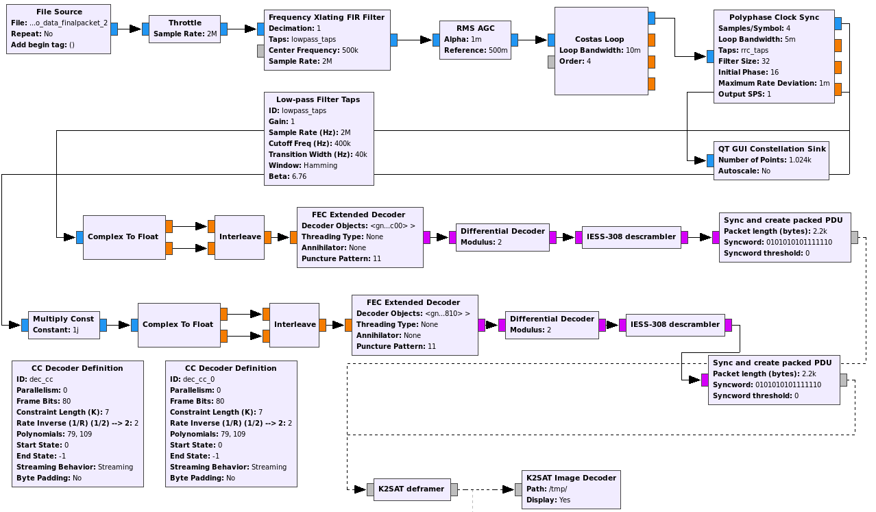
The full GNU Radio decoder flowgraph can be seen in the image below (click on the image to view it in full size).
The 2Mbps data rate includes FEC, so the maximum user data rate is 1Mbps. The STX supports the full data rate of 2Mbps and also reduced data rates of 1Mbps, 500kbps and 250kbps.
Regarding framing, the STX doesn’t implement any particular form of framing, so it is up to the user to implement their own. When transmitting data, the STX has two transmission modes: the synchronization mode and the data mode. In synchronization mode the transmitter will send repeatedly the CCSDS 32bit syncword 0x1ACFFC1D. This can be used to achieve byte synchronization in the receiver. In the data mode, the transmitter will send and consume the user data available in the TX FIFO, or the dummy data byte 0x55 whenever the TX FIFO is empty. When changing from synchronization mode to data mode, the STX also transmits a 0x55 byte before starting to send data from the TX FIFO. The change from synchronization mode to data mode may happen after any byte in the 32bit syncword, not only after a complete repetition of the whole 32bit pattern.
Therefore, to transmit packetized data, the user should put the transceiver in synchronization mode and start filling the TX FIFO with the beginning of the packet. When the TX FIFO is full and some time has passed so that the syncword has been repeated enough, the user should switch the STX to data mode and keep feeding the TX FIFO with the packet data. When all the packet has been fed to the TX FIFO and the TX FIFO empties, the user can switch off the STX. Depending on how fast this is done, additional 0x55 bytes may be transmitted at the end of the packet.
The framing for K2SAT is based on the AX.25 Telemetry and Telecommand Transfer Frames Format document originally prepared by the Swiss Space Centre for SwissCube, which was then used for the QB50 project. An older (but still valid to understand K2SAT framing) version of this document may be found here.
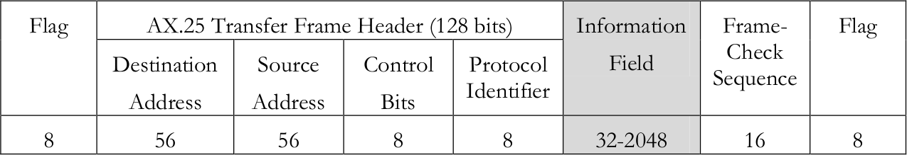
The Telemetry and Telecommand Transfer Frame format uses AX.25 UI (unnumbered) frames and includes a secondary header to provide additional functionality. The figure below shows the usual AX.25 packet, which is fully described in the AX.25 2.2 spec.
The secondary header and the payload are stored inside the information field, formatted as shown in the figure below.
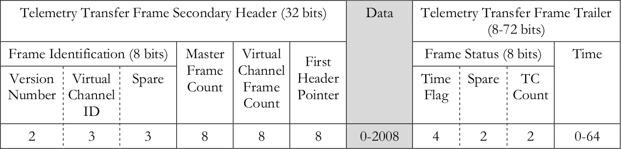
The current version number is 00. The virtual channel ID enables up to 8 simultaneous channels. The master frame counter and virtual channel frame counter are counters which count the number of packets sent (modulo 256) for this physical channel and for this virtual channel. They are used to detect packet loss. The first header pointer is used to handle fragmentation inside the data field (see the document for more details). The time flag indicates whether the optional time field is present (and its size). The TC count indicates the number of telecommands received, and is used to detect packet loss in the uplink.
Note that the secondary header losely resembles the CCSDS TM Space Data Link Protocol.
K2SAT uses the Telemetry and Telecommand Transfer Frame Format as indicated in the figure below.

The JPEG image is fragmented in chunks of up to 2023 bytes and transmitted in the data field. The first header pointer field is repurposed as follows: 0x00 indicates that this is the first chunk of the image; 0xFF indicates that this is the last chunk of the image; and 0xEE indicates any other situation (a chunk which is neither the first nor the last). The optional time field is not sent by K2SAT.
K2SAT has a few deviations from the AX.25 standard that it is worth mentioning. The first is that NRZI or bit stuffing is not used. This makes the detection of packet boundaries a bit difficult. In standard AX.25, bit stuffing ensures that the 0x7e HDLC flag cannot happen inside the packet. In the case of K2SAT nothing prevents the byte 0x7e from appearing inside the packet data.
Second, the CRC16 that is used is not the same as in standard AX.25. Using the notation from this website, standard AX.25 uses CRC16_X_25, while K2SAT uses CRC16_CCIT_FALSE. The difference is that in AX.25 the input and output are reflected and the output is XORed against 0xFFFF, while K2SAT doesn’t do this. Another difference is that in standard AX.25 the CRC covers the whole AX.25 packet, starting by the beginning of the destination address and ending with the last bit of the information field. In K2SAT the CRC also covers the initial 0x7e flag that comes before the destination address.
The framing used by K2SAT relates to the STX synchronization system as follows. A JPEG image is sent using several AX.25 frames without stopping the transmitter. At the beginning of the transmission, the STX is in synchronization mode so the repeating sync vector is sent. At some point, the transmitter is changed to data mode, so a 0x55 byte is sent. This byte is immediately followed by the 0x7e flag marking the packet start and then the first frame of the image is transmitted. After the final 0x7e flag of this packet, the STX continues in data mode. Therefore, several 0x55 bytes are sent until the next packet starts, first sending its 0x7e flag. This process continues until the last packet of the image is sent. After that, more 0x55 bytes are sent and then the transmitter turns off.
Knowledge of this interaction between the K2SAT framing and the STX enables us to detect packet boundaries more reliable (without this knowledge it would be rather difficult or inefficient). The K2SAT deframer in the GNU Radio receiver uses 0x557e to detect the beginning of the packet, using my “Sync and create packed PDU” block. When the sequence 0x557e is found, the 2200 bytes following this sequence are extracted into a PDU. This ensures that the full packet fits into the PDU.
The end of the packet is detected in the following manner. The PDU is scanned for the sequence 0x7e555555. When this sequence is found, it is assumed to mark the packet end and the CRC is checked. If the CRC check is successful, then the packet is passed along to the image re-assembler. If the CRC check is not successful, it is assumed that this is not the packet end and the PDU is scanned further in case another 0x7e555555 appears later. This packet boundary detection scheme is very reliable and more or less efficient.
The image re-assembler receives the PDUs and assembles the chunks to form the JPEG file. Packet lost is detected by looking at the virtual channel counter. In case a packet is lost, the reception of the image fails, since in general this is not a recoverable error because the size of the lost chunk is not known (in practise, K2SAT always uses the maximum chunk size except for the last chunk). The GNU Radio receiver uses feh to show the image in real time as it is being received. This is something I have already done for other image receivers such as those for BY70-1, D-SAT and 1KUNS-PF.
The image receiver for K2SAT is included as k2sat_image.grc in the apps/ folder of gr-satellites. To run, it needs the following example IQ file (206MB), which is a recording of the engineering model transmitter done by the K2SAT team. This file is a 2Msps IQ file containing a JPEG image transmitted at 500kbaud (500kbps taking FEC into account). The image can be seen in the figure below.
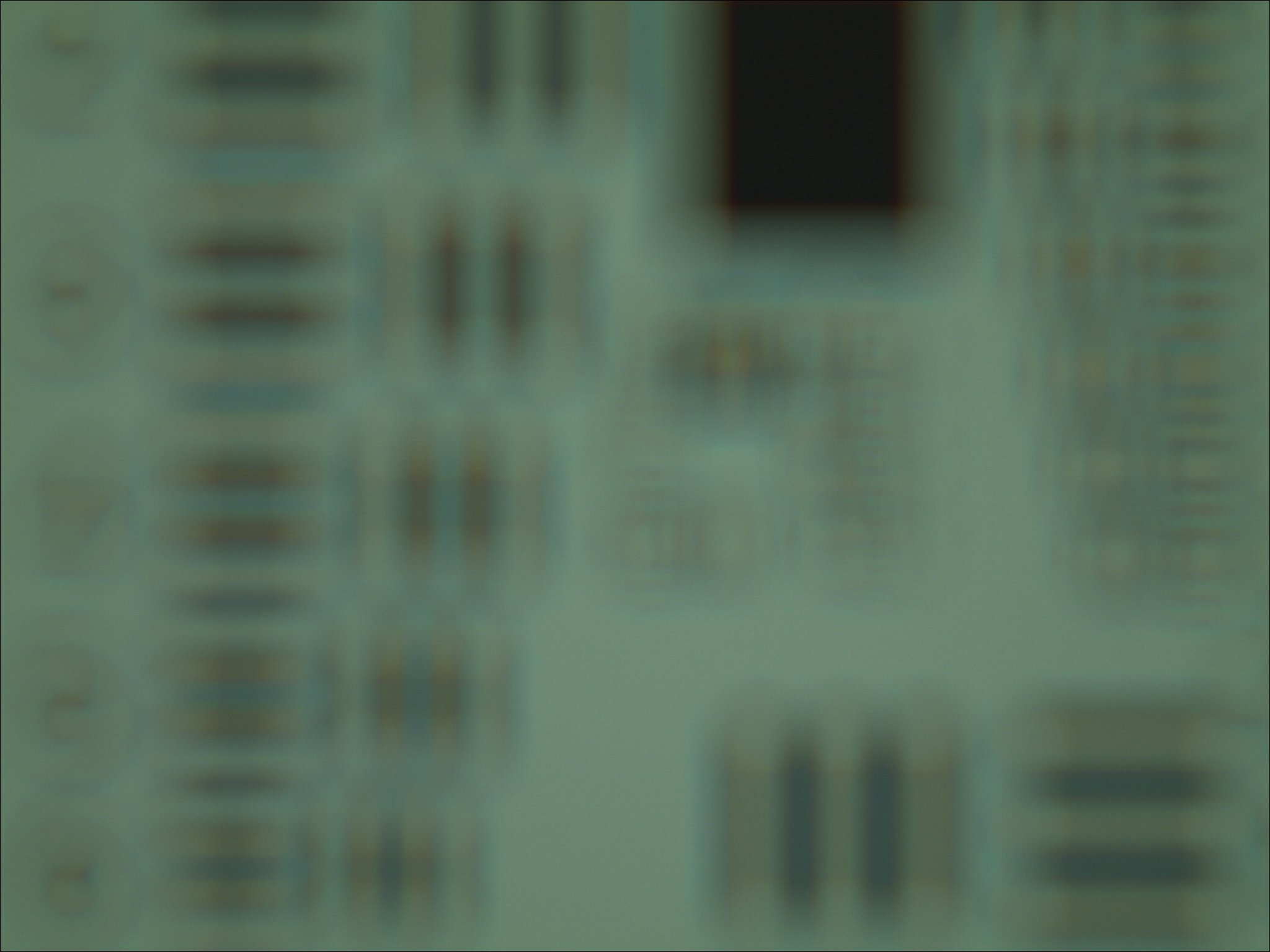
Its resolution is 2048×1536 and its size is 178024 bytes, so it should take 5.7 seconds to transmit without taking packet overhead into account. The QPSK transmission takes a total of 7 seconds.
It will be quite interesting to try to receive K2SAT when it gets launched. As far as I know, this is the first Amateur satellite that has a fast data mode (where fast means anything higher than 50kbaud) with a publicly available decoder. Other Amateur satellites have used fast transmitters in the S-band, but only their team had access the decoder.
Can’t wait to try it out! Is there any pre-launch estimate of what size antenna (dish?) will be required? Also, do we know if this will be a standard LEO polar orbit? Thanks!
Hi Scott,
I don’t have the full details for the transmitter, but the S-band transmitter they use has a maximum output power of 1W. They will probably use a nadir-pointing patch antenna with a gain of 8dBic by the same manufacturer or something similar. You can run your own calculations with this EIRP.
However, as a ballpark estimate, I expect that this signal will be of comparable strength to the ISS HamTV system (which uses 10W and a patch antenna). The power of K2SAT is lower, but the antenna pointing should be better. Also, I understand that HamTV always uses 2Msps, but this will most likely use lower speeds.
This satellite will be in LEO orbit, but I don’t know if it will be polar.
Thank you! I was just hoping to get some idea if even a high-quality omni antenna might be possible for a ground station or if rotator tracking with a dish or helix will be required.
An omni will probably be insufficient. Most likely you will need a small dish (say, 1m) with a rotator.
That is very helpful – thanks!
Great writeup! Was able to reproduce very easily. What modifications to the flowgraph might be made to capture live signal once launched over say RTL-SDR or USRP?
Hi Tony,
You just need to replace the file source block by an appropriate source block for your SDR and do filtering and decimation according to the sample rate you use.
Hi Daniel,
Thank you for your great jobs.
Is there any calculation error on 500 kbaud to 250 kbps with FEC. I think 500 kbaud QPSK is equal to 1 Mbps (Without FEC) and 500 kbps with FEC. Am I wrong?
Hi Mustafa, you are correct. It seems my mind slipped when writing this, as I’m more used to working with BPSK.
Hi Daniel,
That’s really useful !!!
But I don’t know why we need to interleave the signal in two branches after the demodulation?
Hi Jeff, that’s done to handle the 90º phase ambiguity in the Costas loop.
Hi Daniel,
Thank you for your answer. I’ve searched many paper for the phase ambiguity. I still didn’t know why we can handle that by interleaving the IQ data.
Hi Daniel,
We are using the same transmitter (STX) in our next CubeSat. This is the first time I’ve worked with something other than UHF/VHF frequencies so this has been a great source, thank you.
However I’m still having trouble decoding the transmitted signal. I transmitted raw data (sync keyword + some bytes) without any frame, recorded an IQ file using LimeSDR and SDR#, but couldn’t manage to display the decoded data. Any idea what could I be doing wrong?
Hi Eser,
I’m glad that you found this a useful resource. Any clues about where the problems in your receiver could be? Without more details, there are many parts that may not be working as expected. For instance, are you able to lock a good QPSK constellation? Are you able to find the syncwords? Is the Viterbi decoder working (meaning that it is correcting few errors, or that the path metrics are not so high)?
I’m not able to get a good constellation.
For full-rate transmission, the points slightly gather around the edges but for other data rates they are either concentrated around the center or make a diagonal.
Hi, in that case I think you need to work on improving your QPSK demodulator (or perhaps the quality of the signal you’re testing with). Only when you get a good constellation you can start caring about the subsequent steps.
Since it’s the same transmitter as the one you used for this project I don’t think I can do anything better at this point. I’ll try using the SDR directly as the source instead of an IQ recording to see if anything changes. Thanks.
Thank you for the great writeup. I tried the grc file in the examples folder with the IQ file given in the link. Unfortunately I couldn’t reproduce the image given in the article as output. Is there a specific gnuradio and gr-satellites release that I can try? I tried with the master branches of both, compiled from source.
Thanks Robert.
Probably you could use the Git history to try to match the date of the post with the version of gr-satellites that I used. It was certainly with GNU Radio 3.7, so something pretty old.
I don’t think going back with versions is a good idea. I would rather try to fix what’s wrong in the current version. Do you get at least some decoded frames?
Thank you for your reply. On Raspberry Pi, I have decoded 87 sequences of the image according to the logs of ImageReceiver block. The model outputs a jpeg file which gives an unsupported marker type error on Rpi when opened, on Windows and Mac I can open the file but it looks missing.
Hi Daniel, i have read your article and it was very well written. But i am having a doubt which i want to ask. Why have not you demodulated the signal ? You have directly decoded it after after polyphase clock sync.
What do you mean? The flowgraph includes a rather standard QPSK demodulator. What do you think is missing?
Hi Daniel, according to this article https://wiki.gnuradio.org/index.php?title=QPSK_Mod_and_Demod
A constellation decoder block is used. I think constellation decoder block or constellation soft decoder block should be there after polyphase clock sync block to recover decoded symbols and bits. If i am wrong, please make me correct
You are wrong. In a QPSK modulation, soft bits can be extracted directly from the real and imaginary parts of the symbols, which is what this flowgraph is doing. A Constellation Decoder block could be used, but it is not the only possible solution.
Ok Daniel, means i can use constellation soft decoder block in place of complex to float block in flowgraph ?
Yes. You could. If you configure it appropriately.