The Harbin Institute of Technology satellites LilacSat-2, BY70-1 and the upcoming LilacSat-1 all use a concatenated code with an \(r=1/2, k=7\) convolutional code and a (255,223) Reed-Solomon code according to the CCSDS TM Synchronization and Channel Coding blue book specifications. The GNU Radio decoder gr-lilacsat by Wei BG2BHC includes a custom implementation of the relevant part of the CCSDS stack, probably ported into GNU Radio from some other software.
Recently, I have been working on decoding KS-1Q and I’ve seen that it uses the same CCSDS coding as the HIT satellites. This has made me realise that most of this CCSDS coding can be processed using stock GNU Radio blocks, without the need for custom blocks. The only exception is Reed-Solomon decoding. This can be done easily with gr-libfec, which provides an easy interface from GNU Radio to Phil Karn’s libfec. Here I look at the details of the CCSDS coding and how to process it with GNU Radio. I’ve updated the decoders in gr-satellites to use this kind of processing. I’ll also talk about the small advantages of doing it in this way versus using the custom implementation in gr-lilacsat.
Here I focus in the decoding process. The encoding process just follows the same steps backwards. The first step in processing the CCSDS coding is Viterbi decoding of the \(r=1/2, k=7\) convolutional code. Here, it is important to understand how the convolutional code works, as there are several possible variations in the implementation. If the bitstream to be encoded is denoted by \(\{x_n\}_{n=-\infty}^\infty\), the encoder produces two streams\[\alpha_n = \sum_{k=0}^6 a_k x_{n-k},\quad \beta_n = \sum_{k=0}^6 b_k x_{n-k}.\]Here the calculations are done in \(GF(2)\). Usually, the coefficients \(a_k\) and \(b_k\) are encoded as the coefficients of the polynomials\[p_A(z) = \sum_{k=0}^6 a_k z^k = 1+z^2+z^3+z^5+z^6,\\p_B(z) = \sum_{k=0}^6 b_k z^k = 1+z+z^2+z^3+z^6\]Therefore, \(\{a_n\}\) and \(\{b_n\}\) are obtained as the convolution of \(p_A\) and \(p_B\) respectively against the input bitstream. This is what gives the convolutional code its name.
In the implementations, the polynomials \(p_A\) and \(p_B\) are usually called POLYA and POLYB and they are encoded in a byte as \(0a_6a_5a_4a_3a_2a_1a_0\) and similarly for POLYB. Thus, POLYA = 0x6d and POLYB = 0x4f.
The possible variations of the code account for how the sequences \(\{\alpha_n\}\) and \(\{\beta_n\}\) are transmitted. The most straightforward way is to transmit\[\ldots,\alpha_{n-1},\beta_{n-1},\alpha_n,\beta_n,\alpha_{n+1},\beta_{n+1},\ldots,\]so the \(\alpha\)’s and \(\beta\)’s are transmitted in turns starting with the \(\alpha\)’s. In the implementation, it is usual to say that the code first uses POLYA and then POLYB. This is what the GNU Radio “Decode CCSDS 27” block expects. However, it is not what it is used in many implementations.
If you have been reading my Outernet posts, perhaps you recall that the M7 Inmarsat modem transmits\[…,\beta_{n-1},\alpha_{n-1},\beta_n,\alpha_n,\beta_{n+1},\alpha_{n+1},\ldots\]In other words, it first uses POLYB and then POLYA. It is also common practice to invert one of the sequences (which corresponds to adding \(1\) in \(GF(2)\)). The NASA-DSN convention is to transmit\[\ldots,1+\alpha_{n-1},\beta_{n-1},1+\alpha_n,\beta_n,1+\alpha_{n+1},\beta_{n+1},\ldots\]The CCSDS/NASA-GSFC convention is to transmit\[\ldots,\beta_{n-1}, 1+\alpha_{n-1},\beta_n,1+\alpha_n,\beta_{n+1},1+\alpha_{n+1},\ldots\]In the implementations, this inversion is encoded by using -POLYA instead of POLYA. Therefore, NASA-DSN is first -POLYA and then POLYB and CCSDS/NASA-GSFC is first POLYB and then -POLYA.
Be aware that replacing POLYA by -POLYA has no real mathematical meaning. It is just a software trick to encode that the bitstream corresponding to POLYA should be inverted. Since the constraint of the code is 7, the most significant bit of POLYA and POLYB is 0, so it can be used to encode whether inversion is needed. The software then looks at the sign of the byte which encodes the polynomial and acts accordingly. For instance, see this excerpt from viterbi27_port.c in libfec:
void set_viterbi27_polynomial_port(int polys[2]){
  int state;

  for(state=0;state < 32;state++){
    Branchtab27[0].c[state] = (polys[0] < 0) ^ parity((2*state) & abs(polys[0])) ? 255 : 0;
    Branchtab27[1].c[state] = (polys[1] < 0) ^ parity((2*state) & abs(polys[1])) ? 255 : 0;
  }
  Init++;
}
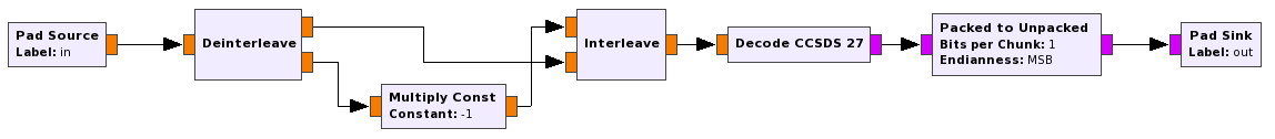
With this in mind, it is very easy to transform the convolutional coded bitstream into the convention that the stock GNU Radio block “Decode CCSDS 27” expects. The flowgraph below does Viterbi decoding with the CCSDS/NASA-GSFC convention. It is a hierarchical block, so it can be used in other flowgraphs. It outputs an unpacked bitstream, which is generally more useful than the packed bytestream that “Decode CCSDS 27” outputs.
After Viterbi decoding, there is an optional step which consists in differential decoding. A differential code is only used when there is an ambiguity in the polarity of the signal, such as when the modulation is BPSK. It is not used for FSK. A “Differential Decoder” block with “Modulus = 2” can be used to perform this step. In gr-lilacsat, this step is called M-code, and the implementation uses a Gray decoding lookup table. This implementation managed to confuse me for a while, since I didn’t understand how this M-code was supposed to work, as we haven’t achieved byte synchronization yet. However, I realised that this implementation is just doing differential decoding, but working on bytes with a lookup table (which by some interesting property of Gray coding, it turns out to be the same table that you would use for Gray decoding).
Note that sometimes convolutional coding is not used (for instance, in the LilacSat-2 300bps subaudio telemetry), therefore, the Viterbi decoding step is skipped in these cases. The next step in the processing chain is synchronization. The 32bit syncword is 0x1acffc1d. After the syncword, we have to extract \(8(F+32)\) bits, where \(F\) is the frame length in bytes and 32 accounts for the Reed-Solomon parity check bytes. This can be accomplished easily in GNU Radio by using “Correlate Access Code – Tag” to find the syncword and “Fixed Length Packet Tagger” from gr-synctags and “Tagged Stream to PDU” to extract a PDU with the packet. This is done in the hierarchical block shown below for ease of reuse.

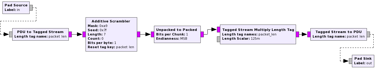
After synchronization, we need to perform descrambling. The scrambler used in the CCSDS stack is an additive (synchronous) scrambler. Its polynomial is usually written as \(p(x)=x^8+x^7+x^5+x^3+1\), but if using the notation I used in my post about scramblers, it should be \(q(x)=1+x+x^3+x^5 + x^8\). Note that \(q(x) = x^8p(x^{-1})\) is just the reversed polynomial of \(p\). So, if thinking in terms of LFSRs this difference in notation is just a matter of which way the elements of the LFSR are numbered. The seed is all ones regardless of which notation you use. Therefore, in GNU Radio we can use an “Additive Scrambler” block with “mask = 0xa9”, “seed = 0xff” and “length = 7”. See my post about scramblers for how to arrive at these parameters, especially the mask.
We do descrambling in a hierarchical block. It expects PDUs containing unpacked bits from the previous step in the chain and outputs PDUs containing packed bytes, which are more useful for Reed-Solomon decoding.
After descrambling, Reed-Solomon decoding is performed. The stock GNU Radio blocks do not provide a good way to do Reed-Solomon decoding (it is not supported by the gr-fec framework currently). Therefore, I use my gr-libfec, which provides an easy interface from GNU Radio into the functions decode_rs_8() (CCSDS code with conventional basis) and decode_rs_ccsds() (CCSDS code with dual basis) from libfec. The block “Reed-Solomon” decoder expects a PDU with a codeword on the input and it outputs a PDU with the decoded message. It only takes a parameter “Verbose” which controls if the decoder outputs the number of byte errors to the console or not and a “Basis” parameter, where you can select either conventional or dual basis. The padding for the shortened Reed-Solomon code is calculated from the size of the input PDU. It doesn’t support erasures. It is convenient to note that the CCSDS standard specifies dual basis representation (not conventional representation). KS-1Q follows this, but the satellites from HIT (LilacSat-2 and -1 and BY70-1) use conventional representation instead.
The CCSDS stack processing ends with Reed-Solomon decoding. However, both HIT satellites and KS-1Q do something interesting. The packets that one gets after Reed-Solomon decoding are not the CSP packets (all these satellites use CSP). Instead, they form part of a KISS stream. The CSP packets are framed inside this stream. This is not a bad idea, as it allows for several things. First, it allows for Reed-Solomon frames to be all the same length, because padding by 0xc0 bytes at the end of the packet can be used. This works because a KISS stream consisting of 0xc0 bytes is just idling. The satellites from HIT use a (146,114) shortened code and KS-1Q uses the full (255,223) code. Second, it allows for several small CSP packets to be fitted inside one Reed-Solomon frame. Third, it allows for idle frames consisting only of 0xc0 bytes to be sent between the useful frames. This is used to maintain a continuous transmission even if there is not enough data to transmit, which simplifies the tracking of the signal. I hear that this is currently being used with BY70-1. Finally, it would allow transmitting CSP packets which are larger than a Reed-Solomon block, although I haven’t seen any satellite doing this. Processing the KISS stream to extract the CSP packets in GNU Radio is easy. We can use “KISS to PDU” from gr-kiss.
KS-1Q also includes a twist of this concept, because after Reed-Solomon decoding each frame has a 3 byte header with the spacecraft ID and type of packet (presumably only one type is in use). After this 3 byte header, the KISS stream follows. The HIT satellites also have a special requirement. Usually the first byte of a KISS frame is a control byte. This is what the standard specifies. However, the HIT satellites use no control byte, so the first byte of the KISS frame is already the first byte of the CSP packet. I have added an option in “KISS to PDU” to account for this.
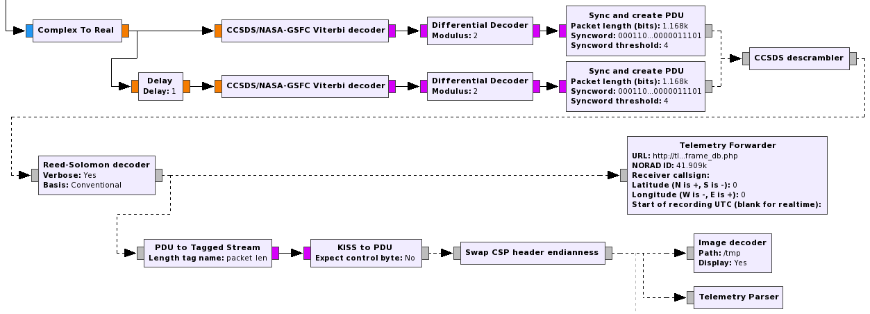
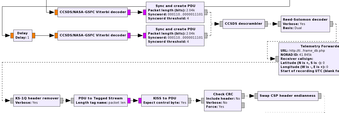
Below you can see a couple of examples of the processing chain of some decoders in gr-satellites.
The advantages that I see in doing the processing in this way versus using the implementation in gr-lilacsat are as follows. First, we are reusing much more code from GNU Radio, so it is easier to track bugs down and do improvements. It is also important to be able to split the whole CCSDS processing stack into well defined hierarchical blocks that can be used for other satellites that may use a similar coding. This eases the maintenance of gr-satellites and makes it easier to support new satellites. Also, it is probably easier for someone who wants to understand how everything works to study this implementation using hierarchical blocks.
Finally, there are some small advantages from the practical point of view. Viterbi decoding is now always done using soft symbols. In contrast, the decoder for LilacSat-2 9k6 FSK telemetry in gr-lilacsat uses hard symbols. Also, the Viterbi decoder from GNU Radio is slightly different to the one used in gr-lilacsat. Both use unsigned bytes for the soft symbols. The decoder in gr-lilacsat maps the range [-1,1] into [0,255], clamping to 0 or 255 everything outside [-1,1]. The decoder in GNU Radio, however, maps [-1,1] into [28,228], clamping to 0 or 255 everything that would fall outside [0,255] using this linear (or rather affine) mapping. I haven’t run any performance test, but this second approach seems more sensible. Another small advantage is that now the threshold for finding the syncword is easy to set. In gr-lilacsat it is hardcoded to 1 bit error at most, which might be too low in some circumstances.
KS-1Q use a FPGA for telemetry & telecommand baseband processing. dual-basis RS(255,223) code uses fewer element in hardware implementation. Lilacsat use a STM32 to encode / decode RS code, which conventional RS code will be faster.