Peregrine Mission One is a lunar lander built by Astrobotic Technology. It is the first mission to be launched under the NASA Commercial Lunar Payload Services program, and Astrobotic’s first mission. It was launched in January 8 from Cape Canaveral in the maiden flight of ULA‘s Vulcan Centaur. Shortly after the launch, the team detected an issue with a propellant leak that prevented the spacecraft from achieving a soft landing on the Moon. Since then, the team has continued operating the spacecraft to the best of their capacity and collecting as much engineering and science data as they can for the next mission. Astrobotic has been doing a superb work of communicating the progress of the mission with regular updates in the Twitter account, which should specially be praised because of the difficulties they’ve faced. Congratulations for all they have achieved so far, and best luck in the upcoming missions.
In this post I won’t speak about propulsion anomalies, but rather about low-level technical details of the communications system, as I usually do. Peregrine Mission One, or APM1, which is NASA DSN‘s code for the mission, uses the DSN groundstations for communications, as many other lunar missions have done. However, it is not technically a deep space mission. In CCSDS terms, it is a Category A mission rather than a Category B mission (see Section 1.5 in this CCSDS book), since it operates within 2 million km of the Earth. Communications recommendations and usual practices are somewhat different between deep space and non-deep space missions, but APM1 is specially interesting in this sense because it differs in several aspects of what typical deep space missions and other lunar missions look like.
For this post I have used some IQ recordings done by the AMSAT-DL team with the 20 metre antenna at Bochum Observatory. To my knowledge, these recordings are not publicly available.
Modulation and coding
Alan Antoine F4LAU did a preliminary analysis of modulation and coding shortly after launch. The signal is PCM/PSK/PM, which means that telemetry is BPSK modulated on a subcarrier, which is then phase modulated with residual carrier onto the RF carrier. The baudrate is 13 kbaud, and the subcarrier frequency is 1024 kHz. Due to the large subcarrier over baudrate ratio, the signal leaves a huge empty gap between the data subcarrier and the residual carrier, and occupies much more bandwidth than it should. For a baudrate as low as 13 kbaud, typically much lower subcarrier frequencies of around 60 kHz are used. This is a CCSDS recommendation even for Category A missions (see 2.4.14A in the blue book). I wonder if there was a reason behind the choice of such a large subcarrier frequency, such as perhaps using the gap between the data subcarrier and the residual carrier for ranging signals, to somehow use the large separation of the data subcarriers for navigation, or to accommodate much larger symbol rates using the same subcarrier frequency.
The coding is the CCSDS C2 LDPC code. This is a code that is designed for near Earth missions that need to operate at high data rates on the order of 100 Mbps. It focuses on low encoding and decoding complexity to allow these fast rates, rather than on achieving very good Eb/N0 performance. Thus, it is favoured by Earth observation satellites and similar missions, which need to transfer large volumes of data but usually have good link budgets. Section 8 of the TM Synchronization and Coding green book contains a more detailed discussion of this LDPC code and how it compares with the AR4JA family of codes, which are designed for good Eb/N0 performance and are the ones that are typically used in deep space and lunar missions (for instance, the Artemis I Orion vehicle used the r = 1/2 AR4JA code).
The C2 code has a rate of approximately 7/8. More precisely, the rate is 223/255, since the C2 code is an (8160, 7136) code designed so that the coded block and information block sizes are exactly 4 times those of the Reed-Solomon (255, 223) code. This makes it easier to replace Reed-Solomon by the C2 code in existing systems. The DSN has good support of the C2 code, as can be seen at the bottom of Table 3 in this document. Nevertheless, I can’t help but think that using the C2 code instead of an AR4JA code for this mission is an unusual and interesting choice. To me, the C2 code feels like a thing typical of low Earth orbit satellites, not deep space or lunar missions. Maybe Astrobotic based their communications system on existing low Earth orbit technology. This is not necessarily a bad thing. After all, there is a reason why the DSN supports the C2 code in addition to the AR4JA codes.
Since I hadn’t dealt with the C2 code before, I have added a command to ldpc-toolbox to generate the alist for the code. This allows me to use gr-ldpc-toolbox (or any other LDPC decoder that supports alists) to decode the LDPC codewords. However, the C2 code is somewhat peculiar because it is obtained from a basic (8176, 7156) LDPC code by expurgation, shortening and extension. The following figure is a good representation of what these operations involve.
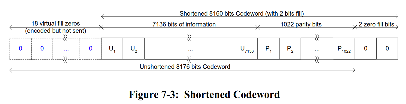
The LDPC decoder works with the unshortened 8176 bits codeword, but what we receive is the shortened 8160 bits codeword. Therefore, to decode it is necessary to discard the symbols corresponding to the 2 zero fill bits, and add 18 symbols with LLRs that indicate a very high confidence in the bit zero in the place of the 18 virtual fill zeros. We treat the resulting codeword as a codeword of a systematic (8176, 7154) code with the same alist as the basic code (note that the value of \(k\) differs by 2 from that of the basic code), and drop the first 18 bits of the decoded codeword. This gives us the 7136-bit information word. All these operations can be done with stream and vector operations in GNU Radio, so it is possible to adapt the LDPC decoder from gr-ldpc-toolbox to work with the C2 code by adding some external blocks.
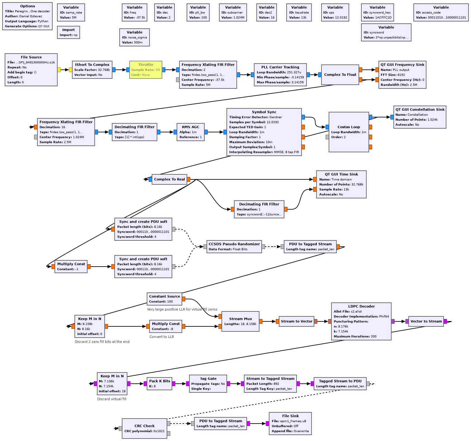
The following figure shows the GNU Radio flowgraph that I have used to decode Peregrine Mission One. The first part of the flowgraph is a typical demodulator for PCM/PSK/PM. The second part of the flowgraph includes the LDPC Decoder block from gr-ldpc-toolbox and the auxiliary blocks used for the codeword manipulations.
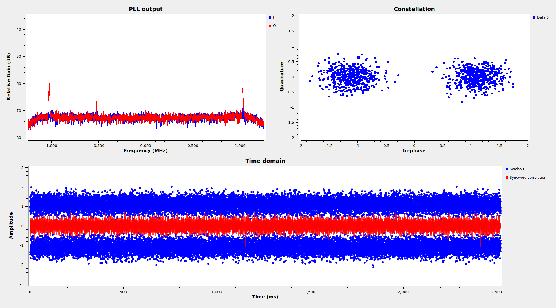
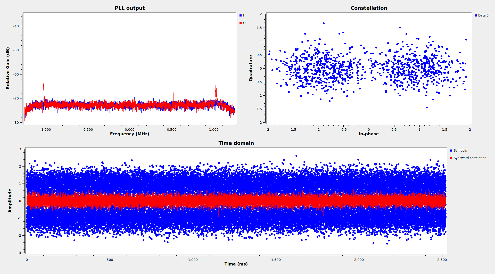
This is the GUI of the flowgraph running on one of the AMSAT-DL recordings. In this case the SNR is very good and there are no bit errors, but the signal has some periodic fading, and there are times when the SNR becomes much worse. The large empty space between the data subcarrier and the residual carrier can be seen in the spectrum. There are CW tones at what appears to be one half of the subcarrier frequency. I don’t know if these are an artefact of the signal generation, or purposely used for navigation.
AOS frames
For this analysis I have used a recording done on 2024-01-08 22:10:22 UTC. The recording has a duration of 1 hour and 6 minutes.
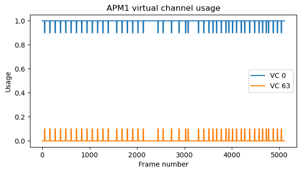
The frames are CCSDS AOS frames. The spacecraft ID is 0xE0. This doesn’t appear to be in the SANA registry. Virtual channels 0 and 63 are in use. Virtual channel 0 contains telemetry, and virtual channel 63 is the only-idle-data virtual channel. There are very few frames from virtual channel 63, since most often there is something to send on virtual channel 0. All the frames have a Frame Error Control Field (CRC-16), which is checked by the GNU Radio decoder.
All the bytes in the virtual channel 63 frames, except for the AOS primary header and the FECF, are filled with the value 0x8d. This is an unusual choice. The values 0xaa or 0x55 (which have alternating ones and zero in binary), 0x00, or an 8-bit counter, are more common choices.
The frames in virtual channel 0 use the M_PDU protocol to carry CCSDS Space Packets. These frames also have an Operational Control Field (OCF) carrying a Communications Link Control Word (CLCW). The contents of the CLCW of the first decoded frame in virtual channel 0 are the following.
Container:
control_word_type = False
clcw_version_number = 0
status_field = 0
cop_in_effect = 1
virtual_channel_identification = 0
rsvd_spare = 0
no_rf_avail = False
no_bit_lock = False
lock_out = False
wait = False
retransmit = False
farm_b_counter = 1
rsvd_spare2 = 0
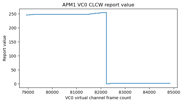
report_value = 245
The only field that changes value throughout the recording is the report value, which increments as each telecommand is received. The value of this field is plotted here. In total, 14 telecommands were received during the recording.
The next figure shows the frame loss in virtual channel 0, computed using the virtual channel frame count. There are periods when no frames are lost, but there are other periods where the frame loss is much higher. In total, there is a frame loss of around 14%.
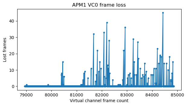
The periods when there is large frame loss correspond to fading in the signal. I haven’t tried to optimize the decoder for best results, but at times the constellation plot looks like this due to fading. The C2 code needs around 4 dB Eb/N0 to work, and probably the fades are going below this value.
The next figure shows the virtual channel usage, measured in 10 frame averages. Each spike in VC 63 corresponds to a single frame.
Space Packets
There is something quite unusual about the Space Packets transmitted in Virtual Channel 0. Most of them have the value 1 rather than 0 in the packet version number field in the primary header. The CCSDS Space Packet Protocol blue book specifies that the packet version number field should be zero. This is a somewhat confusing aspect of CCSDS: protocol versions are numbered starting by 1 (so the Space Packet Protocol is actually version 1), but the version number field encodes version minus one rather than version, so its value should be 0, not 1. In fact, packet version numbers are registered in SANA, and packet version 2 (which corresponds to the value 1) was formerly used for SCPS-NP CCSDS 713.0-B-1, but is now deprecated.
More interestingly, the packets from APID 128 correctly have a value of 0 in the packet version number field. However, the packets from the rest of the APIDs have the value 1. I wonder what is special about APID 128. Maybe it is generated by a different software. Due to this mistake with the packet version number, I had to patch my Space Packet defragmentation code, since it checks the packet version number as a sanity check.
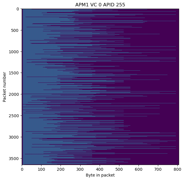
APID 255 is used for idle Space Packets. This is another deviation from the CCSDS standard, which specifies that the idle APID should be 2047 (all ones in a 11-bit field). Maybe Peregrine Mission One is limited to 8-bit APIDs for some reason, because all the APIDs used are smaller than 256.
The packets in all the APIDs except APID 255 have the secondary header flag enabled. It appears that the length of the secondary header is 10 bytes. The first 2 bytes have a relatively small set of possible values: 0x044f, 0x082f, 0x083f, 0x08ee, 0x0c3f, 0x0c4f. I don’t know what these mean. The next two bytes are always 0x001e. The remaining 6 bytes are a timestamp, encoded as a 32-bit integer giving the number of seconds elapsed since the J2000 epoch (2000-01-01 12:00:00) and a 16-bit integer giving the fraction of the second.
I think that perhaps the 0x1e preceding the timestamp is intended to be the CCSDS P-field that describes the format of the timestamp. Such a value would indicate correctly the length of the integer seconds and fractional seconds fields, but it also indicates the CCSDS standard epoch of 1958-01-01, rather than an agency-defined epoch (which is what should be used for the J2000 epoch).
The payload of APID 255 packets starts by 0x083f001e0000 (unless the packet payload is shorter than 6 bytes, in which case the payload is trimmed accordingly). This seems quite similar to the secondary header of the non-idle packets, even though the secondary header flag is disabled in this APID. After these 6 bytes, there is ASCII text: first LE, and then IDLE repeating until the end of the packet. Thus, the payload of idle packets is basically filled with repetitions of the ASCII text IDLE. This is a fun detail. Peregrine Mission One is the first spacecraft that I have seen doing this. Other spacecraft use as filler either some Easter egg message in ASCII or something more boring such as 0xaa, 0x55, a counter or a pseudorandom sequence. Interestingly, the repetitions of IDLE start by LE rather than by IDLE. Maybe this is just because of the fixed 6 bytes at the beginning, which overwrite 2.5 repetitions of the 4-character sequence IDLE.
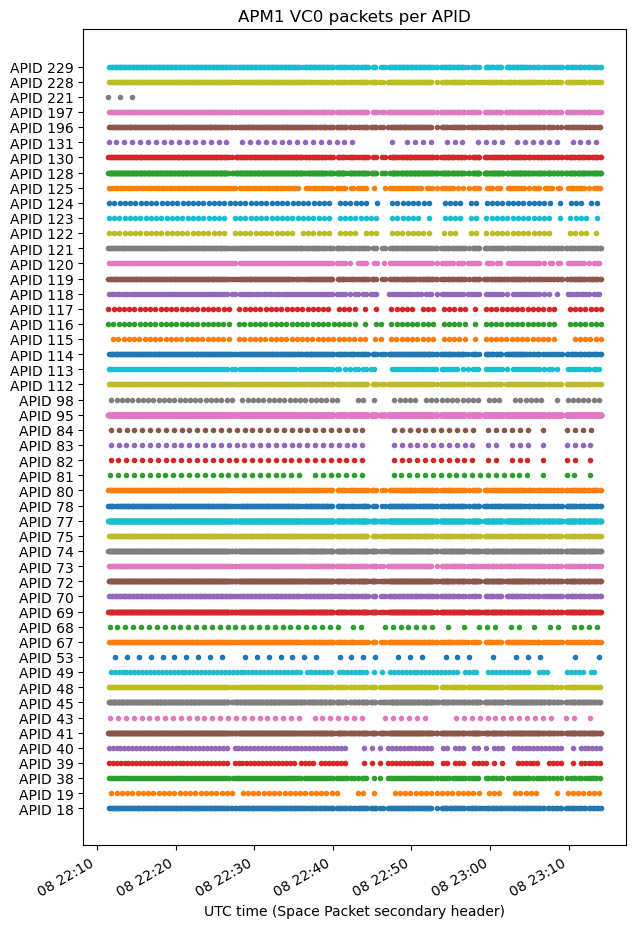
The next plot shows the timestamps of the Space Packets transmitted in each non-idle APID. It is apparent that there are many APIDs in use, and that each of them has a different periodicity. The gaps in some of the APIDs are most likely due to frame loss rather than the spacecraft actually stopping to send these packets (except for APID 221, which clearly stops near the beginning of the recording).
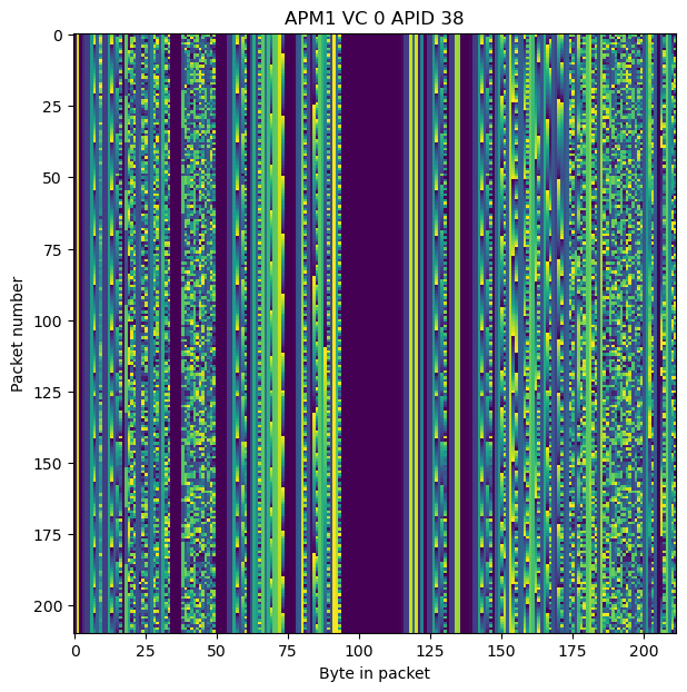
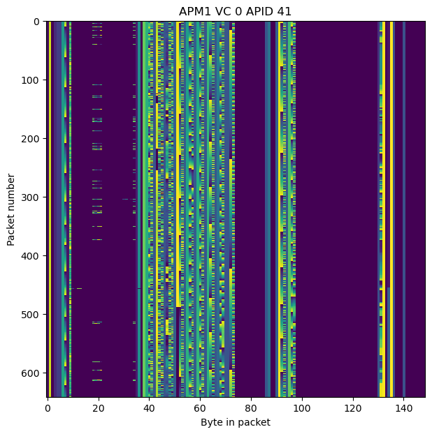
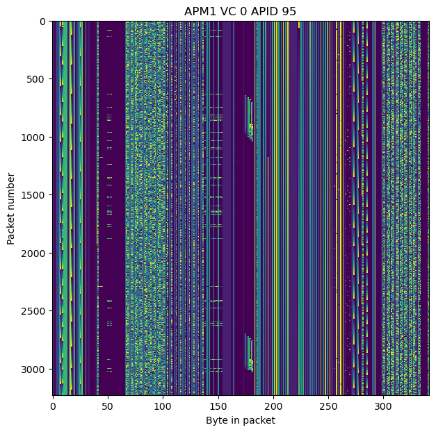
The Jupyter notebook in which I analysed this data contains raster maps for the packets in each of the APIDs. The packets in the non-idle APIDs line up neatly, with fields having the same positions in all the packets in the same APID. In the raster map many numerical fields can be distinguished by the patterns they form. I haven’t taken a look at any of these, because it would be a lot of work, since there is a lot of data that is readily accessible. Here are some representative examples of raster maps. The notebook contains all of them.
The raster map for the idle APID 255 is also interesting to see. The ASCII text shows up in blue, and we see that each packet has a different length (the purple part on the right does not form part of the packets), since they are used to flush an AOS frame by filling the remaining part of its packet zone.
Code and data
The GNU Radio flowgraph and Jupyter notebook used in this post can be found in this repository, together with a binary file containing the decoded AOS frames.
Hi Daniel,
You stated in this article that “these recordings are not publicly available”.
Do you know whether AMSAT-DL will release or will consider publicly releasing the IQ recordings for the peregrine mission?
It would be nice to obtain an IQ recording for an actual link that uses the CCSDS/NASA (8160, 7136) LDPC code if possible.
Thanks and also a very interesting article again,
Dave M
Hi Dave, I’ve asked AMSAT-DL about this and they will not publicly release these recordings.