The DSCS satellites are a constellation of US military communication satellites. While the constellation is old and it is being replaced by WGS, there are still several active DSCS-III satellites. A few days ago, Scott Tilley VE7TIL tweeted about the DSCS-III-A3 X-band beacon. The satellite DSCS-III-A3, also known as USA-167, is the second most recent DSCS-III satellite, having been launched in 2003. It has an X-band beacon at 7604.6MHz.
Scott’s tweets included a very impressive and interesting find: a Master’s thesis about a DSCS-III beacon decoder made by James Coppola in 1992. The thesis contains a wealth of information about the beacon, as well as the complete C source code for the decoder.
Scott has also been kind enough to share with me some recordings that he made of the beacon, so in this post I’ll be looking at these and how they relate to the information in the thesis.
The modulation on its own is not very interesting. As you can see in Scott’s tweet below, the beacon has a central narrowband carrier and two other narrowband carriers spaced some 75kHz away from the centre frequency. The central carrier is an 800baud BPSK signal, while the carriers on the sides are 1kbaud BPSK signals. The thesis speaks only about the 800baud signal.
The 800baud signal is demodulated with the GNU Radio flowgraph dscs_demod_800baud.grc, which is just a simple BPSK demodulator that outputs soft bits. The soft bits are then examined in a Jupyter notebook.
The thesis explains that the 800 baud beacon is organized in 8-bit frames. Each of the bits in the frame can be thought of as a TDMA channel, as shown in the table below.
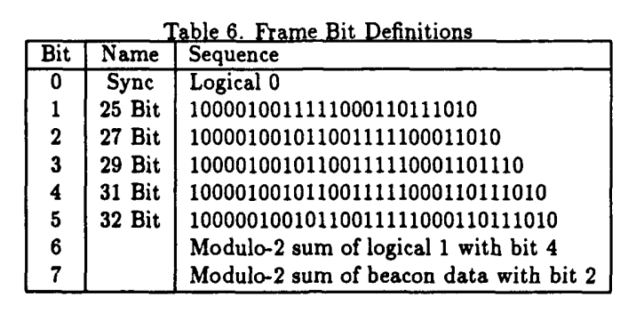
The first channel contains a constant stream of zeros, so it can be used for frame synchronization and to resolve the BPSK phase ambiguity. Channels 1-5 contain PN sequences of 25, 27, 29, 31 and 32 bits. Since these lengths are pairwise coprime, the combination of the five sequences takes 19418400 frames to repeat (which corresponds to 53.94 days). Channel 6 contains the inverse of channel 4 (I’m not so sure about the reason behind this design decision).
Now, the thesis says that channel 7 contains the XOR of the telemetry and channel 2. This is stated both in the table shown above and in the main text. However, I think this is an error (or at least USA-167 does it differently), since in the recordings that Scott has sent me channel 7 is actually the XOR of the telemetry and channel 3.
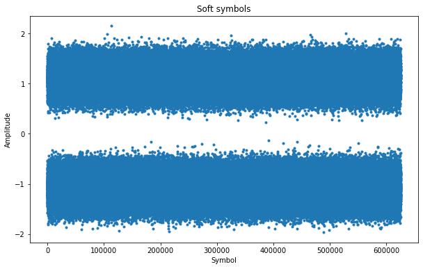
The figure below shows the soft symbols obtained from the demodulator. We see that the SNR is good enough to guarantee that there are no bit errors.
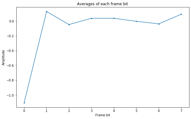
I have grouped the symbols in frames of 8 symbols and performed the average of each of the bits in the frame (i.e., of each channel) to check which one is bit 0. The figure below shows the averages, where I have already aligned the stream so that frame bit 0 is constantly -1, as indicated by the table above.
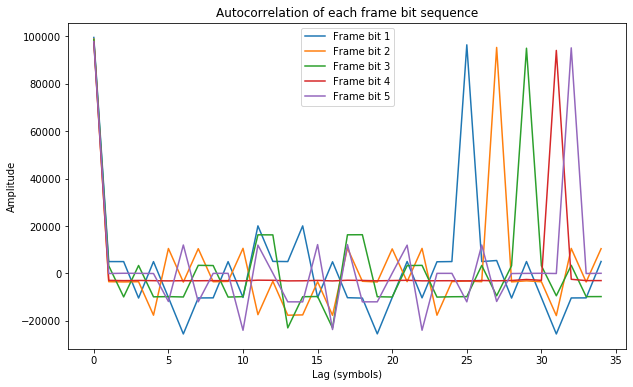
It is interesting to compute the autocorrelation of channels 1 through 5 to check that they contain a repeating sequence of the length indicated in the table above.
I have also checked that channel 6 contains the inverse of channel 4.
Regarding the telemetry data, the thesis says that a telemetry frame has 100 bits. These 100 bits are convolutionally encoded with r=1/2 to produce 200 bits that go in channel 7, so a telemetry frame takes 2 seconds to transmit. As I said, the information in the thesis that the telemetry stream in channel 7 is XORed with channel 2 is incorrect. If we take the XOR of channels 2 and 7 and compute the autocorrelation, we only obtain weak peaks. However, if we take the XOR of channels 3 and 7 instead, then we get strong autocorrelation peaks at lags which are integer multiples of 200 bits.
The description in the thesis about synchronization to the 200 bit data frame is done is shown below.
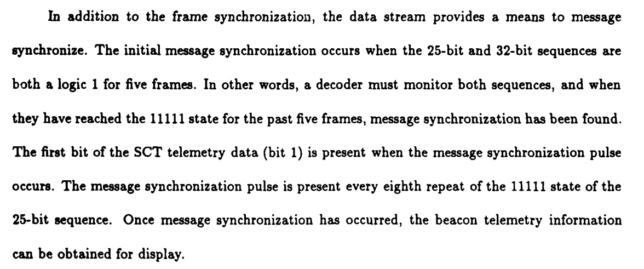
I find this paragraph a bit ambiguous to understand. We can see that the 25 and 32 bit sequences have a single run of 5 ones each (and no longer runs of ones). These runs of 5 ones are transmitted simultaneously every 800 frames, owing to the coprime periods of the sequences. So we learn that whenever the runs of 5 ones in both sequences coincide, there is the start of a data frame. A data frame is only 200 frames long, so there are also data frames starts elsewhere. This is what is meant by “The message synchronization pulse is present every eigth repeat of the 11111 state of the 25-bit sequence”.
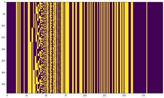
Now, it is not completely clear to me from this paragraph whether the first bit of the data frame is transmitted in the next frame after the coincident runs of 5 ones, or in the last frame of the run, or something else. It turns out that the second option is the correct one.
The figure below shows the data frames already synchronized, with one 200 bit frame per row.
The r=1/2 convolutional code is something rather peculiar. In contrast to the usual convolutional codes, it is systematic. This is said in the thesis only in passing as:
It should be noted that the GPM is the only demodulator/decoder which takes advantage of the convolutional encoder by using it in conjunction with a Viterbi decoder to improve the bit-error-rate performance. The other two receivers just ignore the extra bit.
This is very convenient, since it means that we can throw away the extra bit added by the encoder and obtain the 100 bit data frame, just as the “two other decoders” do. It turns out that the even bits are the data bits, and the odd bits are the FEC bits added by the convolutional encoder. To see this, we split the 200 bit frames into the two possible 100 bit frames, getting the figures below.
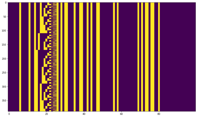
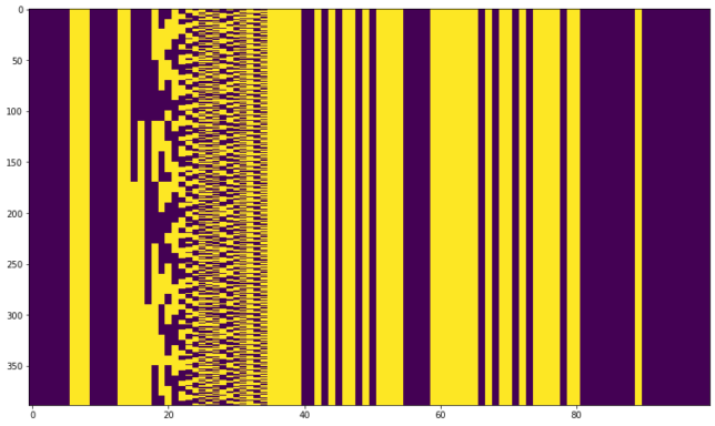
In the even bits we see that most of the data is static (it is the same in all the frames) but there is also something that looks pretty much like a binary counter. In contrast, the behaviour of the odd bits is more complicate and one can even imagine how the effect of the binary counter propagates through the shift register of the convolutional encoder.
A closer inspection at the data for the binary counter reveals that it is not a single counter, but several cascaded counters (which reset at values which are not powers of two). Indeed, the table below shows that the first 48 bits of the telemetry frames are essentially a huge clock. The way the fields are written suggests that BCD is used, and this is indeed the case. It is interesting that the clock value has 5us resolution but it is only sampled every 2 seconds.
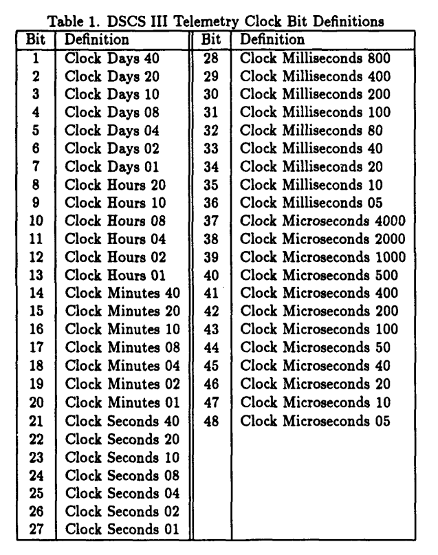
Relating this table to the figure above that shows the data bits, we see that the bits that move as a binary counter correspond to the seconds and minutes. The hours and days do not change, since the recording is not that long, and the milliseconds and microseconds do not change either, since the clock is measured exactly every two seconds.
I have checked that by using the offsets given in this table to read the minutes and seconds I get a counter that increments in steps of two (by the way the least significant bit of the seconds is always set, so the clock counts odd seconds). This validates that I have aligned to the start of the frames correctly.
Pages 9 through 12 in the thesis contain tables describing the remaining bits in the telemetry, but I haven’t explored their values.
Regarding the 1kbaud subcarriers, I have only taken a quick look at the autocorrelation, which doesn’t reveal any obvious patterns. There is a strong negative autocorrelation at a lag of one symbol. This suggests that perhaps the stream is differentially coded and the data stream is unbalanced (there are more ones than zeros). Scott shows that there is an audible event every minute approximately, so at least it should be possible to see what causes this event.
2 comments