Lately, I have been playing around with the concept of doing acquisition and wipeoff of JT9A signals, using a locally generated replica when the transmitted message is known. These are concepts and terminologies that come from GNSS signal processing, but they can applied to many other cases.
In GNSS, most of the systems transmit a known spreading sequence using BPSK. When the signal arrives to the receiver, the frequency offset (given by Doppler and clock error) and delay are unknown. The receiver runs a search correlating against a locally generated replica signal which uses the same spreading sequence. The correlation will peak for the correct values of frequency offset and delay. The receiver then mixes the incoming signal with the replica to remove the DSSS modulation, so that only the data bits that carry the navigation message remain. This process can be understood as a matched filter that removes a lot of noise bandwidth. The procedure is called code wipeoff.
The same ideas can be applied to almost any kind of signal. A JT9A signal is a 9-FSK signal, so when trying to do an FFT to visually detect the signal in a spectrum display, the energy of the signal spreads over several bins and we lose SNR. We can generate a replica JT9A signal carrying the same message and at the same temporal delay than the signal we want to detect. Then we mix the signal with the complex conjugate of the replica. The result is a CW tone at the difference of frequencies of both signals, which we call wiped signal. This is much easier to detect in an FFT, because all the energy is concentrated in a single bin. Here I look at the procedure in detail and show an application with real world signals. Recordings and a Python script are included.
As an example, the image below shows the FFT of a JT9A signal at -27dB SNR in AWGN (over a 2500Hz bandwidth). The signal is at 1400Hz, but it is barely visible.
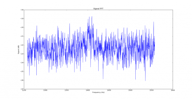
The parameters used for this FFT are a sampling rate of 12000Hz, FFT length of \(2^{16}\) samples, Blackman window, transforms overlapping 50%.
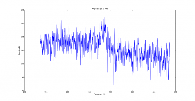
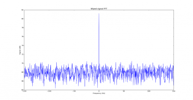
Below we can see the wiped signal. It is around 11dB over the noise floor. The parameters for the FFT are the same as above.
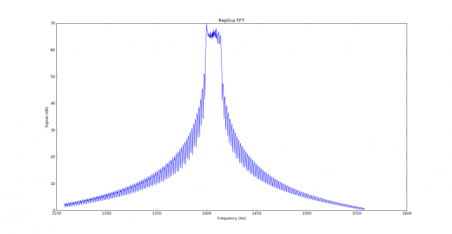
Before looking at correlations between the signal and replica, it is usual to look at the autocorrelation of the replica, to see what properties it has. First we show the FFT of the replica. We can see that a JT9A signal is 15.6Hz wide, so it spreads over many FFT bins. Each FFT bin is 0.18Hz wide, so the signal spreads over 85 bins. After wiping off, we concentrate all the power in a single bin, obtaining an large increase in SNR.
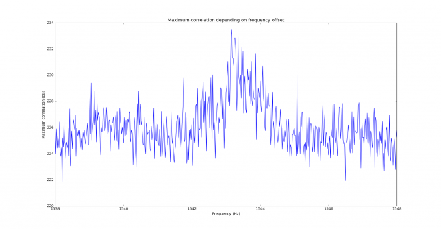
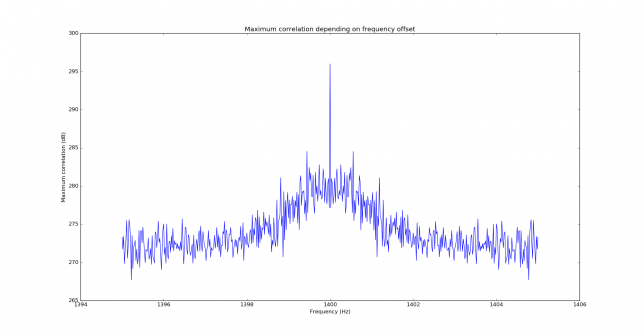
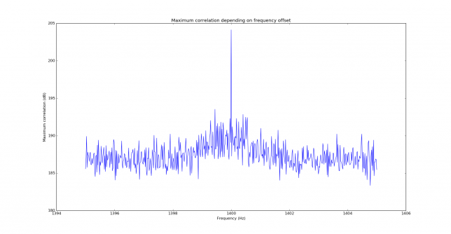
The correlation is performed both in frequency and time. In fact, only the time offset is needed to perform wipeoff, but to obtain the time offset, first the frequency offset must be found, since time correlation only works properly when the frequency offset is known. The figure below shows the maximum of the correlation in time for each frequency offset. By peaking this maximum we find the correct frequency offset. In this case, the signal has been found at 1400Hz, which is the frequency we are using for the replica. We note that the sidelobes in the figure below are 11.5dB down.
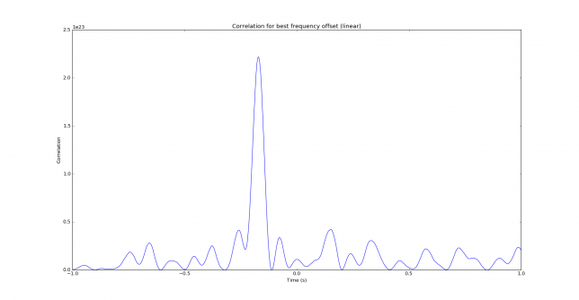
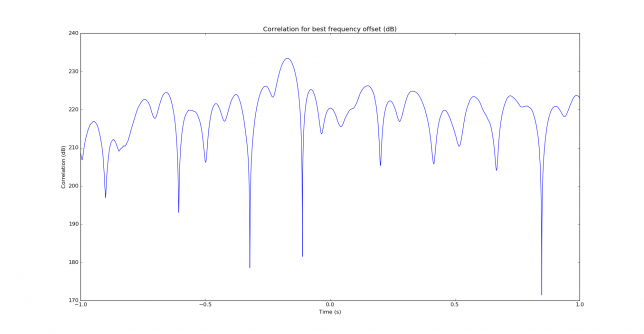
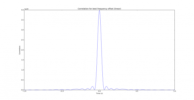
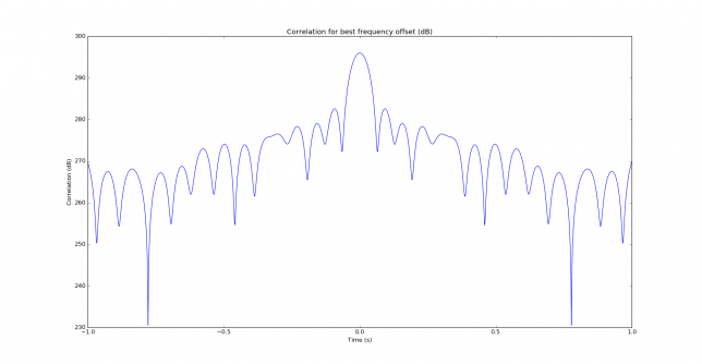
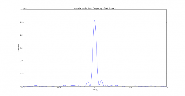
The two figures below shows the correlation in time for the correct frequency offset, in a linear and dB scale. We see that not a lot of temporal resolution is provided by JT9A. This is expected, since the keying rate is rather low. The peak is 3dB down at 29ms time offset, so the temporal resolution given by correlation is on the order of 60ms. This corresponds to 18000km, so multipath cannot be seen by studying the correlation in time.
Still, it is interesting that an m-FSK signal such as JT9A improves the resolution in time. In contrast, an unfiltered BPSK signal carrying a PRN sequence has a resolution in time on the order of the inverse of the baudrate, which for JT9A is 576ms.
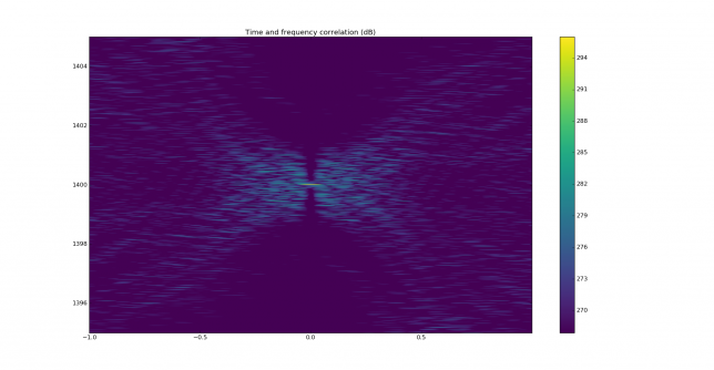
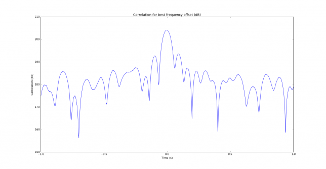
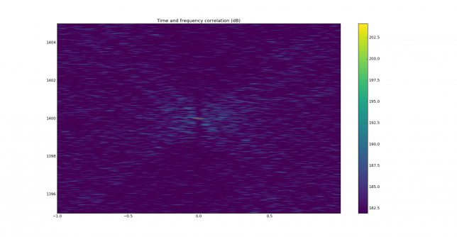
Finally we show the autocorrelation in frequency and time. We can see that, although resolution in time is poor, the resolution in frequency is rather good, and in fact for the correct time offset, the autocorrelation has a very sharp response in the frequency parameter.
Now we show the correlation plots for the -27dB SNR signal over AWGN. They are essentially the same as the autocorrelation of the replica, but with added noise.
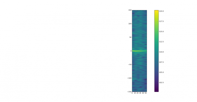
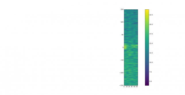
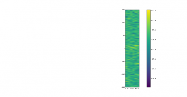
To study time-varying signals, such as signals with fading or frequency drift, a waterfall is quite useful. The figure below shows the waterfall for our -27dB SNR signal. It is barely visible. The parameters are an FFT size of \(2^{15}\), Blackman window, transform overlap of 50% and 6 averaged transforms per waterfall line. The dynamic range is 20dB.
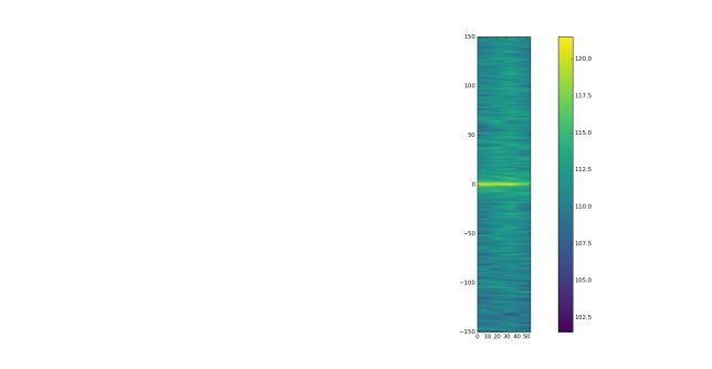
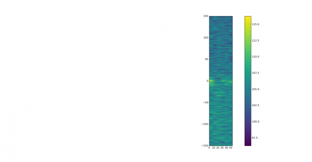
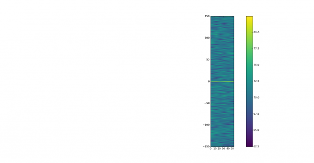
The wiped signal is clearly visible in the waterfall below, which was computed with the parameters given above.
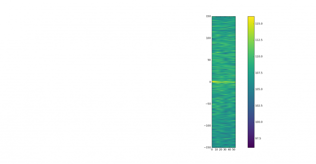
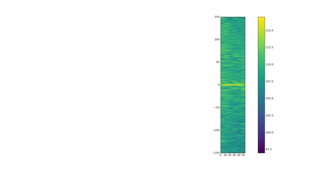
For signals having large frequency spread it is sometimes useful to compute a waterfall with a coarser resolution in frequency, using an FFT size of \(2^{14}\), Blackman window, transform overlap of 50% and 16 averaged transforms per waterfall line. The dynamic range is also 20dB.
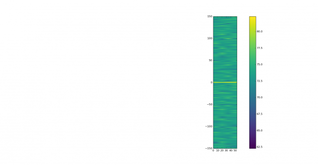
While this procedure works beautifully with ideal signals such as our -27dB SNR over AWGN signal, real world signals have multipath, Doppler spread, phase noise and all sorts of things. These factors make the correlation more difficult by spreading the correlation peak. Also, after wipeoff, the wiped signal inherits all the spectral properties from the original signal. For instance, if the original signal drifts in frequency, the wiped signal will also drift in frequency in the same way.
This is interesting because it can serve as a way to analyse the propagation path: Doppler spread can be judged better on a single tone in the wiped signal, reflections off aircraft scatter are visible by their Doppler shift in the wiped signal and so on. In fact, this is one of the practical applications that I see for these techniques. On August 5, Iban EB3FRN and I were doing some tests with JT9A over a 403km path in the 2m and 70cm bands. We were not quite sure if we were hearing each other by tropospheric scatter or by aircraft scatter. This is what motivated this research.
Another application is to detect visually the presence of JT9A signals which are a few dB below the decoding threshold. This indicates whether a QSO could be possible if conditions improve slightly. By correlating against the known transmitted message, a large improvement in SNR is obtained.
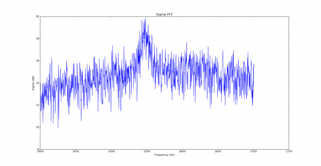
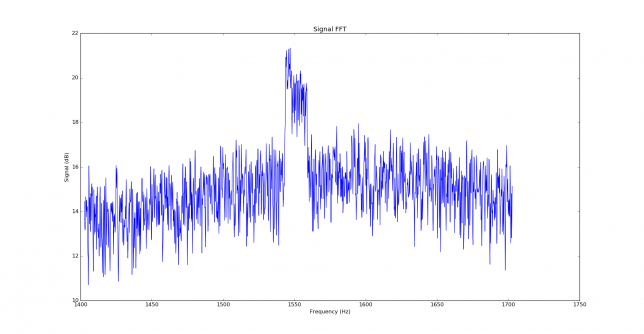
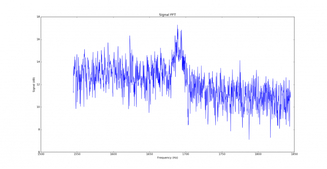
As a real world example, I am using the signals I received from EB3FRN on August 5. We managed a QSO in 2m quite easily, while in 70cm we couldn’t do it, because I only managed to hear Iban once (while he was hearing me most of the time). The first signal decoded from Iban in 2m was at 11:01, with the message “EA4GPZ EB3FRN JN01”. The signal is visible in the FFT plot.
The correlation in frequency produces lots of responses caused by Doppler spread and possibly aircraft scatter reflections.
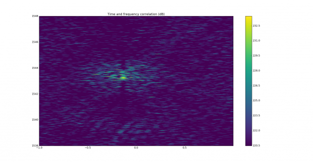
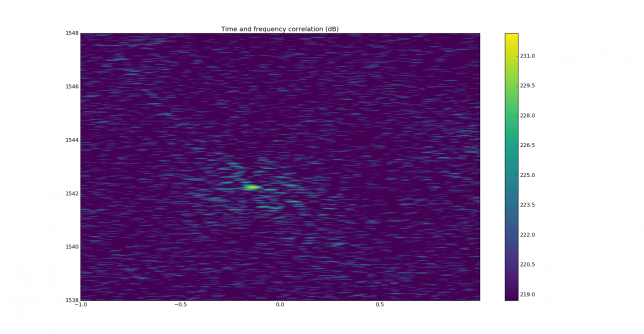
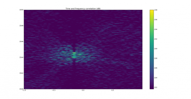
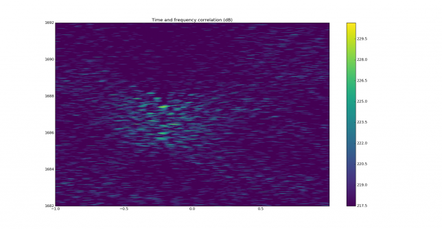
In the time and frequency plot we can see that the main correlation peak is smeared, while there are several other correlation peaks. These should be discarded, as the difference in time delay is too large and not compatible with any multipath that may happen over a 400km path.
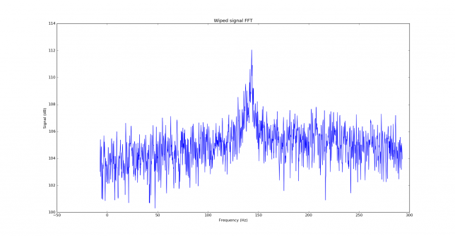
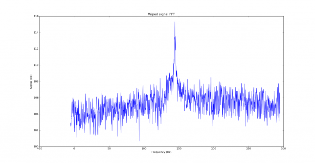
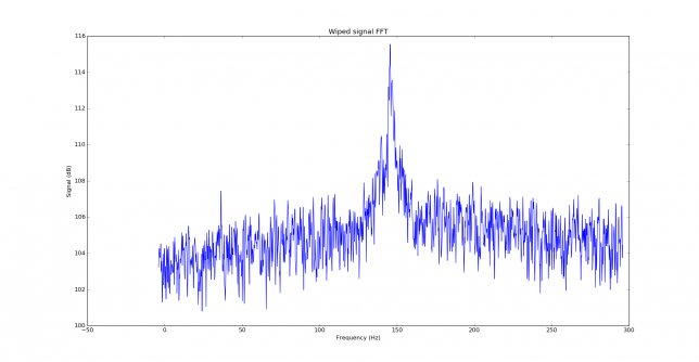
The FFT of the wiped signal shows frequency spread, most likely given by the tropospheric scatter, and responses at some frequencies that might come from aircraft scatter reflections. These are best seen in the waterfall plots.
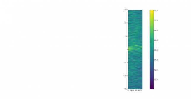
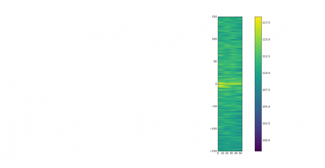
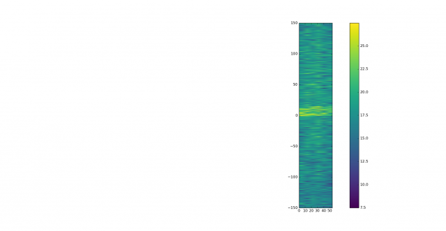
The waterfall plot of the original signal doesn’t show much, except for a strong signal between 0 and 10 seconds, slightly lower in frequency than the main signal.
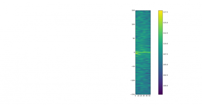
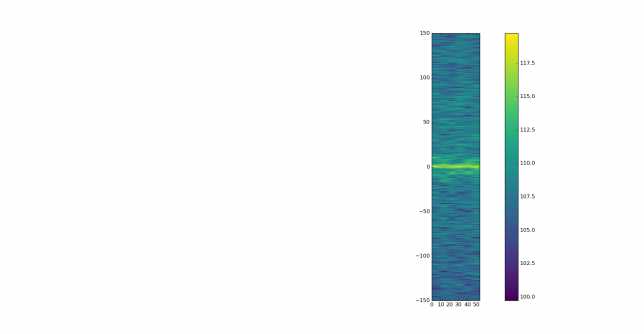
This strong signal can be seen better in the waterfall of the wiped signal. It probably comes from aircraft scatter. The main tropospheric signal can be seen drifting down in frequency slightly, while one can discern two individual reflections at lower frequencies.
These are best seen in the coarse waterfall.
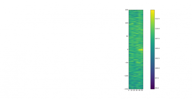
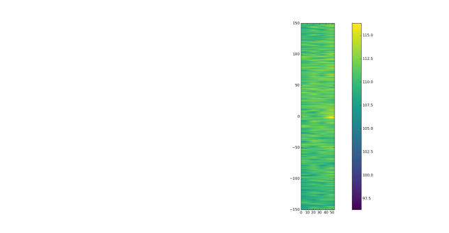
The next signal, at 11:03 didn’t decode, but it shows good correlation against the message “EA4GPZ EB3FRN JN01”. We show the time and frequency correlation and the waterfalls for the wiped signal. It is apparent that the signal was only present for the last 15 seconds of the period, probably received from aircraft scatter.
The signal at 11:05 is the strongest and cleanest signal received. We show the signal FFT, time and frequency correlation, FFT of the wiped signal, waterfall of the signal, and the two waterfalls of the wiped signal.
Below we show the wiped signal corresponding to 11:07, which carries the message “EA4GPZ EB3FRN R-27”.
Next, at 11:15 we have “EA4GPZ EB3FRN RRR”.
At 11:17 we have “EA4GPZ EB3FRN 73”. This signal is strong and interesting, because the FFT of the wiped signal shows a peak 60Hz below the main signal. This could correspond to an aircraft scatter reflection, as 60Hz of Doppler corresponds to around 450km/h. However, this peak is not visible in the waterfall, perhaps because the reflection had a short duration.
At 11:41 we have the only signal that I managed to copy in 70cm. The message is EA4GPZ EB3FRN -22. We show the signal FFT, time and frequency correlation, wiped signal FFT and signal and wiped signal waterfalls. The correlation is quite smeared, the wiped signal is almost as wide as the original signal and the signal is only easily visible during the first 15 seconds, so it seems amazing that WSJT-X can decode this signal.
The SNR in these recordings is not so strong as to bring out all the details of the propagation path. Doing the same experiment with much stronger signals will probably show some interesting details of the Doppler spread caused by tropospheric scatter and perhaps bring out weak aircraft scatter reflections.
The WAV recordings used in this post can be downloaded here (84MB). The Python code I have used is in this gist. The script wipeoff.py can be used in two ways. First, as
wipeoff.py 170805_1101.wav
it will use jt9 to decode the file and get the message and a coarse frequency estimate for the signal. This can be used with files that jt9 is able to decode. If jt9 is not able to decode a file but the message and coarse frequency are known, wipeoff.py can be run as
wipeoff.py 170805_1101.wav 1543 "EA4GPZ EB3FRN JN01"
to get these parameters directly from the command line. The coarse frequency needs to have an accuracy of 5Hz.
