Recently I have been posting about V16 beacons, which are car emergency warning beacons that have been introduced this year in Spain, and which use the LTE NB-IoT cellular network to transmit their geolocation data to the traffic authority network when they are switched on. As part of experimenting with these beacons, I made recording of the downlink and uplink NB-IoT signals while the beacon was sending data to the network. My hope was to be able to decode these signals and extract the two-way traffic that shows how the beacon attaches to the LTE network and sends its data. I already decoded all the uplink transmission in a previous post. In this post I will decode the corresponding recording of the downlink channel.
However, as I already suspected when I was decoding the uplink recording, due to how I physically set up the experiment to avoid saturating the SDR receiver with the beacon transmissions, it turns out that the beacon was talking to an NB-IoT cell that is relatively weak in the downlink recording. More specifically, the antenna for the SDR receiver was set up near a window in the north side of the house, while the beacon was placed on the window sill on the south side of the house. The SDR receiver sees strong downlink signals from cell 145, which is located northeast of the house and is the cell to which the beacon connected in a previous experiment I did with the beacon placed in the north window. However, in this experiment with the beacon on the south window, the beacon connected to cell 261, which is southwest of the house. The signal from this cell is weaker in the downlink recording and is frequently overwhelmed by the signals from cell 145 and other strong cells. So I have had partial success decoding the transmissions that the network sent to the beacon.
This post is mainly about the NB-IoT downlink in general. At the end I focus on the downlink transmissions to the V16 beacon that I have been able to decode. It is a rather long post, because I cover all the main physical channels and signals of the NB-IoT downlink. I show how the NPSS and NSSS primary and secondary synchronization signals and the NRS reference signals work, how to decode the MIB-NB in the NPBCH, how to decode the SIB1-NB and SI messages carrying other SIB-NBs, how to decode NPDCCH transmissions in the Type1 common search space, which corresponds to paging, as well as decoding the corresponding NPDSCH transmissions carrying paging messages, how to do blind decoding of NPDCCH transmissions in the Type2 common search space and UE-specific search space, which correspond to uplink grants and downlink scheduling, and decode the corresponding NPDSCH transmissions that send data to the V16 beacon.
The recording used in this post is published in the dataset Recording of the NB-IoT downlink of a V16 beacon in Zenodo.
NB-IoT downlink signal structure
While writing this post, I have been referring frequently to the paper A Tutorial on NB-IoT Physical Layer Design, by Matthieu Kanj, Vincent Savaux, and Mathieu Le Gue. This is an illustrated and concise introduction to the NB-IoT physical layer which is much easier to follow on a first read than the 3GPP TS documents. The TS documents still need to be consulted for many of the details.
The signal structure depends on whether the cell is FDD, TDD or NTN FDD. Here I will be treating only the FDD case, which is the most common for NB-IoT, because that is what is used in my recording. Additionally, there are some differences depending on whether the NB-IoT carrier is placed in-band (that is, inside the resource element raster of an LTE carrier), or in the guardband or standalone. These differences boil down to the fact that for in-band operation the NB-IoT signal needs to avoid resource elements which are used by the LTE CRS (cell-specific reference signals) and the control region, which occupies the first 1 to 3 symbols of each subframe depending on the configuration. My recording is of a guardband cell, so I will only treat this case.
The following figure, taken from the NB-IoT tutorial paper, shows the signal structure for the NB-IoT downlink in these two modes. Recall that NB-IoT uses a resource element grid that has 12 subcarriers in the frequency domain, and the same structure as LTE in the time domain, which means that each 1 ms subframe is divided into 14 OFDM symbols, of which symbols 0 and 7 have a slightly longer cyclic prefix.
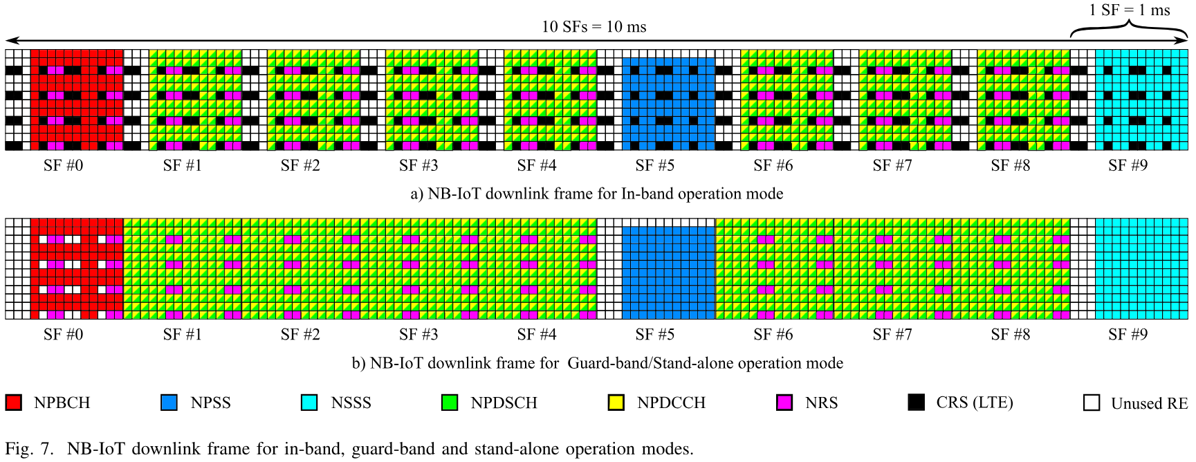
The frame structure repeats every radio frame (10 ms), and within a radio frame, each subframe is dedicated to a given purpose. Subframe 5 is always used to transmit the NPSS (narrowband primary synchronization signal). Subframe 9 is used to transmit the NSSS (narrowband secondary synchronization signal) in even subframes only. Subframe 0 is used to transmit the NPBCH (narrowband physical broadcast channel), which carries the MIB-NB. The remaining subframes, including subframe 9 in odd radio frames, can be used for the NPDCCH (narrowband physical downlink control channel) or for the NPDSCH (narrowband physical downlink shared channel). A given subframe can be used either for the NPDCCH or for the NPDSCH, in contrast to LTE, in which the first 1 to 3 symbols of each subframe are reserved for the PDCCH and other control signals, and the remaining symbols in the subframe are used for the PDSCH. We will see below that subframe 4 plays a somewhat special role because it is where the SIB1-NB can be transmitted. However, the SIB1-NB is carried in the NPDSCH, so from the point of view of the signal structure, this does not have anything special.
There are a few other interesting things to remark related to the above figure. The first is that the NPSS, NSSS and NPBCH avoid the first 3 symbols of the subframe. The reason is that until the MIB-NB in the NPBCH is decoded, the UE does not know if the cell is in-band or guarband/standalone. So the structure of these signals must be the same in all cases, and account for the case in which up to the first 3 symbols in the subframe might be taken up by the LTE control region.
In the case of the NPSS and NSSS, some resource elements may or may not be used depending on whether they are taken by the LTE CRS (this depends on whether the NB-IoT carrier is in-band and on how many antenna ports are used by the LTE carrier). This is fine. Since these signals are intended to be detected by correlation, potentially having some resource elements used for the CRS instead only causes some small correlation losses in the UE. On the other hand, the NPBCH carries data, so in all cases it avoids all the resource elements that can potentially be taken by the CRS (assuming the worst case, which corresponds to 4 antenna ports used by LTE). Note that the location of the reference signals in the frequency domain (both the CRS and the NB-IoT NRS) depends on the cell ID modulo 6. The figure shows the case where the cell ID modulo 6 is zero. In other cases, the locations of these signals in the frequency domain are shifted accordingly.
Another thing to note is that the NPSS does not use the uppermost subcarrier. The reason is that it is based on an 11-element Zadoff-Chu sequence that gets mapped to the lowest 11 subcarriers, as we will see below in more detail.
Finally, the figure shows the NRS (narrowband reference signal) for the case of 2 antenna ports in NB-IoT. This is probably the most common case, and it is what is used in the eNBs in this recording. However, NB-IoT also supports one antenna port. In this case there are fewer resource elements used by the NRS, but the NPBCH still avoids the resource elements corresponding to the 2-port NRS, since the UE does not know the number of ports until it decodes the MIB-NB.
In the case of a guardband/standalone carrier, the NPDCCH and NPDSCH always use all the 14 symbols in a subframe. In an in-band carrier there are higher layer configuration parameters that specify how many symbols are avoided by the NPDCCH and by the NPDSCH at the beginning of each subframe, which is necessary to avoid a conflict with the LTE control region. One drawback of this approach is that the size of the LTE control region can change on a per-subframe basis by using the PCFICH, whereas this setting in NB-IoT is given by the SIB1-NB, and so it cannot change often, and needs to account for the worst case of what the LTE carrier is allowed to do.
Initial waterfall analysis
I always like to look at a waterfall plot with Inspectrum and compare it with the signal structure described above. This is a great way to assess the signal quality and to get an idea of the traffic in the cell. If you know what to look for, it is possible to distinguish many of the physical channels and signals in the waterfall.
The following shows the waterfall of the beginning of the recording. I have used cursors to mark the radio frames so that each signal is easier to find.

In the middle of the radio frames, conveniently at the 0.01 s, 0.02 s and 0.03 s marks just by chance, we have the NPSS. Note that its texture looks somewhat different from the other signals. This is because of the Zadoff-Chu sequence that is used in this signal. The LTE PSS has a similar construction that causes a similarly distinct texture. We can also see that each time that the NPSS is transmitted, it looks somewhat different. We will see why below.
Because there isn’t much activity in this part of the recording, most of the subframes are not in use and they only carry the NRS, which we can see as two vertical bars in each unused subframe. Even though the NRS only occupy one in every 3 subcarriers, here we see the signals from multiple cells, so all the subcarriers are used.
At the beginning of each radio frame we can see that subframe 0 is used by the NPBCH. It is also clear that the first 3 symbols in this subframe are unused. The first radio frame that I have marked is an odd subframe, so it does not carry the NSSS in subframe 9. We can see that the NSSS appears in the next radio frame, at the 0.024 s mark. We also see that subframe 4 (the one immediately preceding the NPSS) is in use. As we will see later, this corresponds to the SIB1-NB transmissions.
The next figure shows a waterfall from another part of the same recording. Here the cell is busy and is using all the available subframes to send the NPDCCH/NPDSCH. Still, we can distinguish the radio frame boundaries and some of the signals. The NPSS always stands out because of its texture. Additionally, the 3-symbol gaps at the beginning of the NPBCH and NSSS (and NPSS) are visible. These serve us to find the frame boundaries and to know what frames are even. In this figure, the frame at the 59.0 second mark is even, since we can see the gap before the NSSS in the last subframe.

NPSS
The NPSS (narrowband primary synchronization signal) is defined in Section 10.2.7.1 of TS 36.211. It is based on a Zadoff-Chu sequence, and constructed as\[d_l(n) = S(l)e^{-i\pi u n (n+1)/11},\]where \(l = 3,\ldots,13\) indicates the symbol number, \(n = 0, \ldots, 10\) indicates the subcarrier number, and the Zadoff-Chu sequence index \(u\) is fixed to \(u = 5\). The sequence \(S(3),\ldots,S(13)\) is given by \(1, 1, 1, 1, -1, -1, 1, 1, 1, -1, 1\). Note that in contrast to LTE, in which a different PSS sequence is used depending on the cell ID modulo 3, in NB-IoT all the cells use the same sequence. This makes sense, because with just 11 elements in the sequence, it is not possible to ensure good enough orthogonality properties between three sequences, unlike with the 63-element LTE PSS sequences.
The following figure shows a cross correlation between the first 100 ms of the downlink recording and the expected NPSS waveform. Before doing this correlation, it is necessary to do a coarse carrier frequency offset estimate and remove it. The NPSS is almost 1 ms long, so if the carrier frequency offset is larger than around ±500 Hz, we will have large sinc losses in the cross correlation. So what I have done is to do the correlation for multiple frequency offsets as a way to estimate and remove the carrier frequency offset.
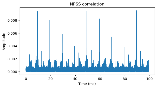
In the correlation plot we can see large peaks every 10 ms. They are slightly before the 10 ms, 20 ms, 30 ms, 40 ms… marks. It is interesting that the amplitude of these peaks varies, and it follows a pattern of 4 peaks. We can see two repetitions of this pattern in the plot, and the start of the next repetition, but the pattern continues like this afterwards.
The reason for this pattern is that the eNBs beamform each NPSS transmission differently, in order to give better chances to UEs to detect the NPSS regardless of their location, because they will be illuminated by one of these beams at some point. The mental image I always have about this is a lighthouse scanning with its beam. TS 32.211 says the following about this in Section 10.2.7.1.2: “UE shall not assume that the narrowband primary synchronization signal is transmitted on the same antenna port as any of the downlink reference signals. The UE shall not assume that the transmissions of the narrowband primary synchronization signal in a given subframe use the same antenna port, or ports, as the narrowband primary
synchronization signal in any other subframe.” This basically says that each NPSS transmission can have a completely independent beam, unrelated to any of the other cell transmissions. Therefore, it leaves the decision fully open to the eNB implementers. Here we see that there is a scan pattern formed by 4 distinct beams, and the pattern repeats regularly.
We also see other peaks in the correlation plot. For instance, there is one around the 13 ms mark, shortly after the first strong peak. Initially I dismissed these peaks as false correlations with other data transmitted by the cells. I did all the analysis of the recording based on the correlation peaks that happen near 10 ms, 20 ms, etc., and I couldn’t find any trace of cell 261, which is the cell to which I knew that the V16 beacon was connected to. When I started writing this post, I noticed these peaks again and decided to investigate more.
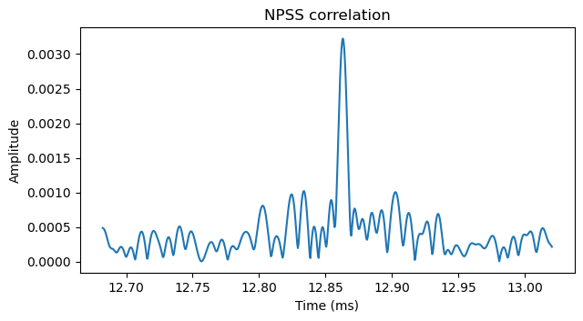
It turns out that these smaller correlation peaks correspond to the NPSS of cell 261, which is not aligned in time with the other cells. I don’t know why this happens, since cells are supposed to be aligned in time to reduce co-channel interference. Many physical layer design choices for LTE and NB-IoT are based on the assumption that all the cells are transmitting in the same time-aligned OFDM raster. So I guess that this particular cell had a synchronization problem, and perhaps no one had noticed.
In fact, if we go back to the Inspectrum waterfall, we can see the NPSS transmissions for cell 261 some 3 ms after the NPSS transmissions from all the other cells. I have marked them in red here. Now that we know they are there, it is even possible to see other transmissions from this cell, such as the NPBCH around the 0.017 second mark.

After realizing this, I had to repeat my analysis by considering a different OFDM raster for cell 261, and then I was able to decode some of the downlink transmission from this cell to the V16 beacon.
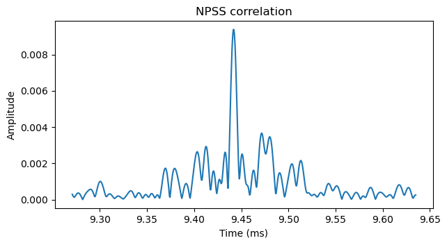
The following plot shows a detail of the first correlation peak, which corresponds to most of the cells that are present in the recording, since they are time-aligned.
The next plot shows a detail of the first weaker correlation peak, which corresponds to cell 261 (and perhaps other cells in the same eNB that are too weak to be detected in this recording).
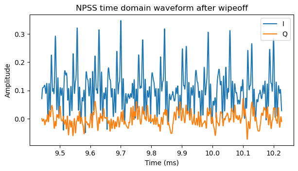
Once the location of the NPSS is known, it is useful to multiply the received IQ data at that location by the complex conjugate of the expected NPSS waveform so as to wipe off the NPSS modulation. We can get a more accurate estimate of carrier frequency offset from the phase rotation over time of the resulting signal. The plot below shows the wipeoff of the first NPSS transmission of all the cells except cell 261. I have applied a constant phase rotation to this waveform so that the result is real and positive, making it is easier to see that there is no phase rotation over time, because the carrier frequency offset has already been estimated and removed.
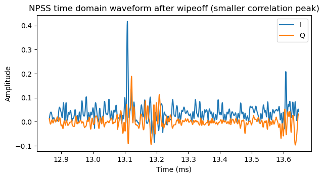
The corresponding plot for the first NPSS transmission of cell 261 is shown here. There is some strong interference from the NRS of the other cells around 13.15 ms and 13.65 ms.
Using the timing obtained from the NPSS correlation, we can perform OFDM demodulation over all the recording. I am doing two independent OFDM grids. One for cell 261, and another for the rest of the cells. OFDM demodulation requires a model of carrier frequency offset and symbol time offset throughout the recording. Initially I begin with a crude model, and I refine the model later on when I get to the NRS reference signals. Then I run OFDM demodulation again with the refined model.
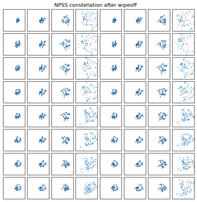
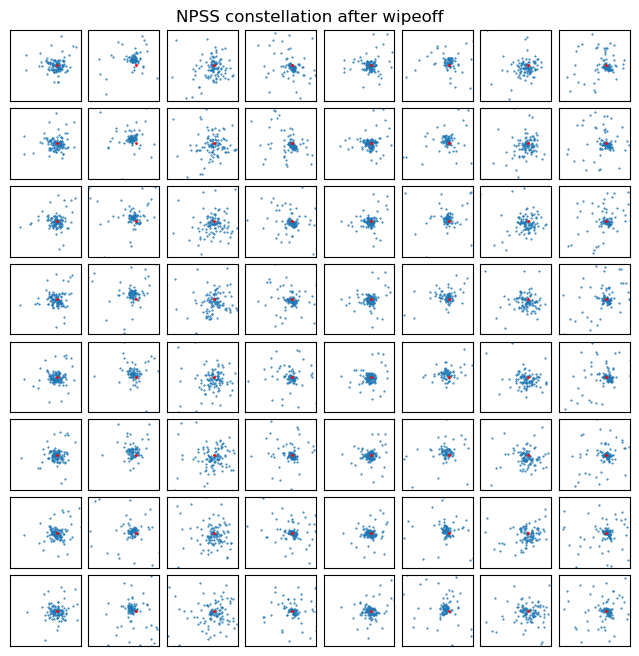
The following plot shows the constellation of the NPSS signal after OFDM demodulation. In ideal conditions we would obtain the Zadoff-Chu sequence symbols, which lie in the unit circle. However, here we can see the amplitude changes in groups of 4 caused by beaming. Also, since we have interference from the signals of multiple cells, the constellation we get is rather ugly.

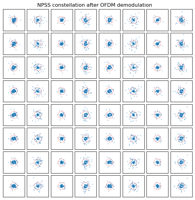
We can wipe off the expected NPSS symbol sequence and use the amplitude and phase of the average of the resulting symbols to do equalization. The result is shown here. We see again the same pattern of groups of 4, where a more spread out constellation indicates a lower SNR. Additionally, we see that in each group the constellation shape is similar but evolves over time. These shapes are caused by the specific way in which all the cells interfere at the receiver.
The corresponding plots for cell 261 are shown here. The SNR is much lower and there is also interference from the NRS of other cells, but on the other hand we don’t get interference from the NPSS of other cells.
A way in which it is more interesting to study the channel for the NPSS is to plot the amplitude over time. Because we have seen that the eNBs use 4 beams sequentially, I am plotting 4 separate traces depending on the SFN (system frame number). The plot below corresponds to the NPSS for all the cells except 261.
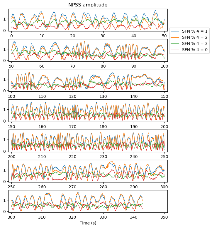
Later we will see that the first NPSS transmission in the recording corresponds to an SFN that is congruent with 1 modulo 4. We can see interference patterns in each of the beams, with “fringe rates” on the order of 0.5 Hz to 1 Hz. Moreover, the fringe rates seem to jump rather discretely. I believe that these are caused by the frequency disciplination of the eNBs. We will see this in more detail in the analysis of the NRS, but they appear to have control loops that do jumps on the order of 1 Hz. Therefore, if the eNBs are in frequency except for an error of a fraction of a Hz caused by these jumps, we will see these fringes as the NPSS of different eNBs interfere constructively and destructively at the receiver.
The corresponding plot for the NPSS of cell 261 is shown here. The first NPSS of cell 261 (the one which occurs about 3 ms after the first NPSS of the other cells) corresponds actually to the next radio frame, so the corresponding beam is SFN congruent with 2 modulo 4.
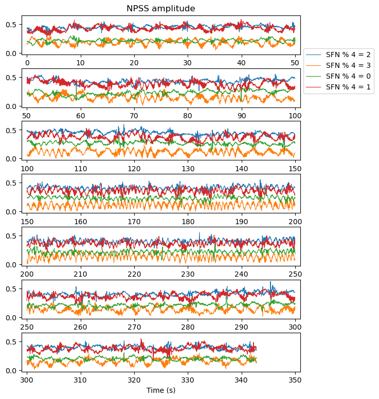
We also see some interference fringes in the amplitude of these beams. The amplitude of the fringes is smaller than in the NPSS of the other cells. These fringes are possibly caused by interference from the NRS of other cells.
NSSS
After detecting the NPSS, a UE uses the NSSS (narrowband secondary synchronization signal) to obtain the physical cell ID and get synchronization to the SFN modulo 8. The NSSS is defined in Section 10.2.7.2 of TS 36.211. It is a sequence of 132 elements that is constructed using a 131-element Zadoff-Chu sequence. The 132-element sequence is mapped to the last 11 symbols in the subframe and to all the 12 subcarriers, in lexicographic order of time and frequency as usual. The sequence is defined as\[d(n) = b_q(m) e^{-2\pi i \theta_f n}e^{-i\pi u n'(n’+1)/131},\]where the index \(n = 0, 1, \ldots, 131\) corresponds to the element number, the index \(n’ = n \mod 131\) is used to index into the Zadoff-Chu sequence, the index \(m = n \mod 128\) is used to index into a 128-element sequence \(b_q\), the Zadoff-Chu sequence index is \(u = (N^{\mathrm{Ncell}}_{\mathrm{ID}} \mod 126) + 3\), and the value \(\theta_f\) is given by \(\theta_f = \frac{33}{132}\cdot(n_f / 2 \mod 4)\), where \(n_f\) is the SFN. There are four 128-element sequences \(b_q\), \(q = 0, 1, 2, 3\), which consist of 1’s and -1’s and are orthogonal. The index \(q\) is chosen as \(q = \lfloor N^{\mathrm{Ncell}}_{\mathrm{ID}} / 126 \rfloor\), so the cell ID \(N^{\mathrm{Ncell}}_{\mathrm{ID}}\) is identified by the pair of numbers \(u, q\). Since the NSSS appears only on even radio frames and the value \(\theta_f\) is different depending on \(n_f / 2 \mod 4\), detection of the NSSS establishes synchronization to the SFN modulo 8.
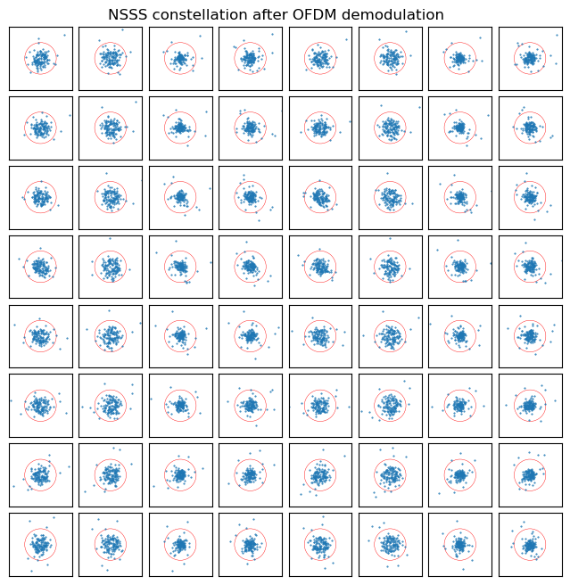
The following plot shows the constellation of the first 64 NSSS transmissions after OFDM demodulation. By construction, the NSSS symbols lie in the unit circle. However, here the constellation is a mess because the sequences used by each cell are different and interfere.
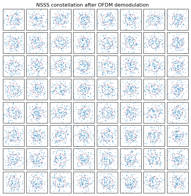
The plot for cell 261 shows a similar mess, although the amplitude is clearly much smaller.
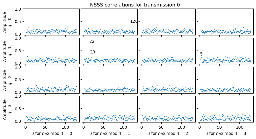
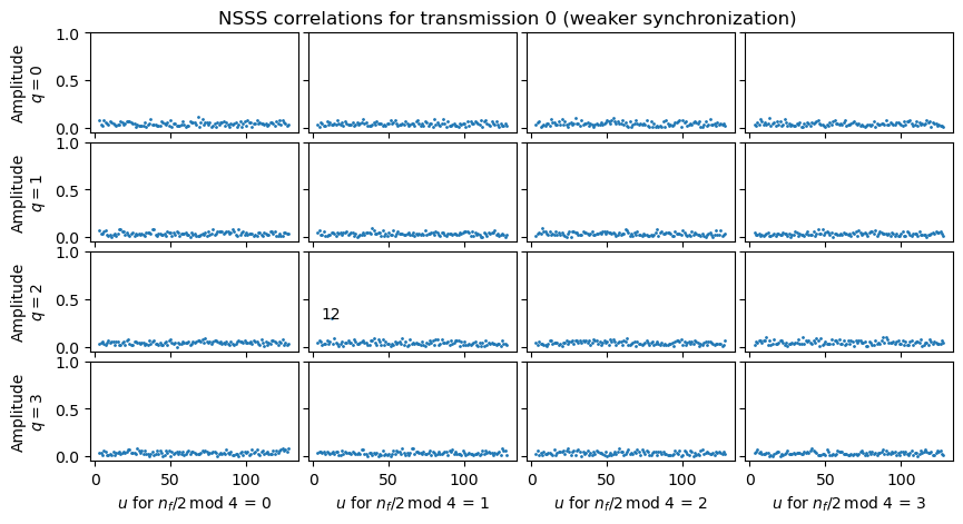
In order to detect the sequences I have used a brute force correlation approach. For each value of \(u = 3, 4, \ldots, 128\), \(q = 0, 1, 2, 3\), \(n_f / 2 \mod 4 = 0, 1, 2, 3\), I generate the corresponding NSSS sequence, use it to wipe off the constellation after OFDM demodulation, perform a coherent average, and take the amplitude.
The plot for the correlation amplitude for the first NSSS transmission in the recording is shown here. The 4 rows correspond to the values of \(q\), the 4 columns correspond to the values of \(n_f/2 \mod 4\), and within each plot the x-axis gives the value of \(u\). For points that are above a certain threshold, the value of \(u\) is labelled next to the point. We see that the detected sequences correspond all to \(n_f/2 \mod 4 = 1\), and that there is \(q = 0, u = 126\), and \(q = 1\), and \(u = 22, 23\).
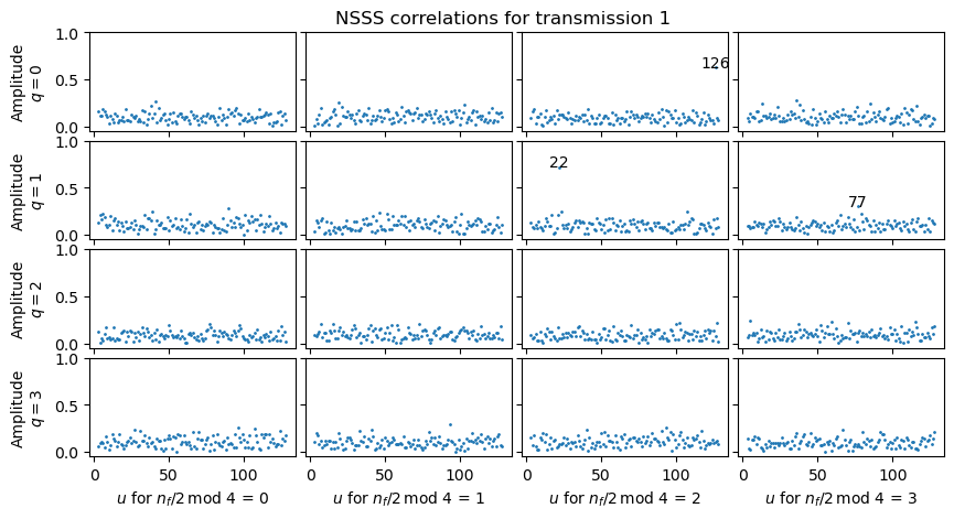
In the next NSSS transmission, we can see that the detections have now shifted to the next column, \(n_f/2 \mod 4 = 1\), as expected. The sequence for \(u = 23\) is no longer detectable, due to changes in the amplitude of these transmissions.
In the next transmission we can see \(u = 21, 22, 23\) for \(q = 1\), but we cannot see \(u = 126\).
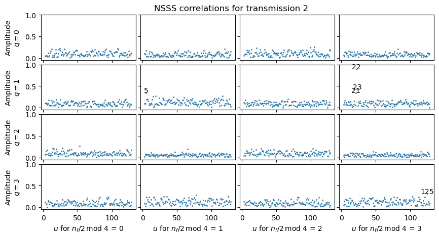
The sequences that we have detected here correspond to cell IDs 123, 144, 145 and 146.
In cell 261, it turns out that the first full radio frame in the recording is even, in contrast to the other cells, for which the first radio frame is odd. In the NSSS correlations for cell 261 we see that \(n_f/2 \mod 4\) is also 1, as for the other cells. We detect \(q = 2, u = 12\), which corresponds indeed to 261.
A technique to detect weaker cells in the NSSS correlation is to perform successive cancellation. The strongest NSSS sequence is selected, its complex amplitude is estimated, and the contribution of this sequence is removed from the received NSSS, iterating again until there are no detected cells.
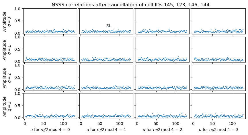
Using this technique with the first NSSS transmission of all cells except 261, it seems that after cancellation of cell IDs 145 and 123, the cell with \(q = 0, u = 71\), which corresponds to cell ID 68, is present.
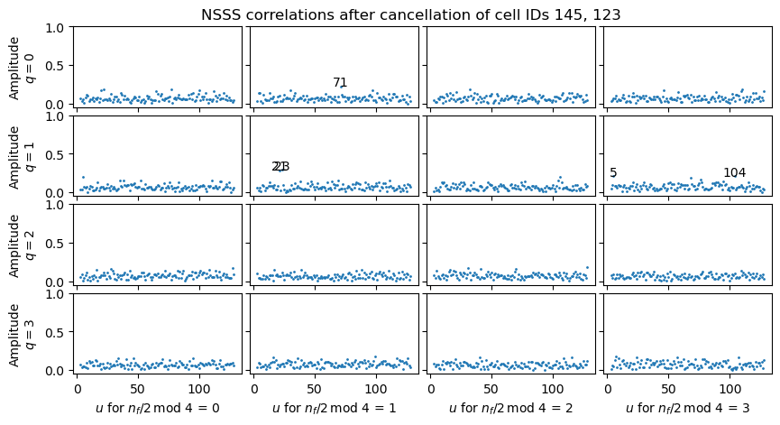
This becomes even clearer after we remove other signals.
From the cells we have detected, cells 144, 145, 146 correspond to the same eNB (note that they all have the same quotient when divided by 3, which means that they belong to the same LTE cell group number). This eNB is located to the northeast of my house, so its signals are good when looking through the north window, which is where the receive antenna was located for this recording. Cell ID 145 corresponds to the eNB sector that illuminates towards the southwest. The other cell IDs correspond to other eNB sectors (144 beams north and 146 beams southeast), and probably they arrive to the receiver through reflections on buildings. I am not quite sure of where cell 123 is. Cellmapper.net doesn’t list this cell. Cell 68 is to the west of the house and there are large buildings in between, so it makes sense that its signal is quite weak. Cell 261 is located to the southwest of the house, so it makes sense that looking from the south window of the house its signals are strong and the V16 beacon decided to connect to it.
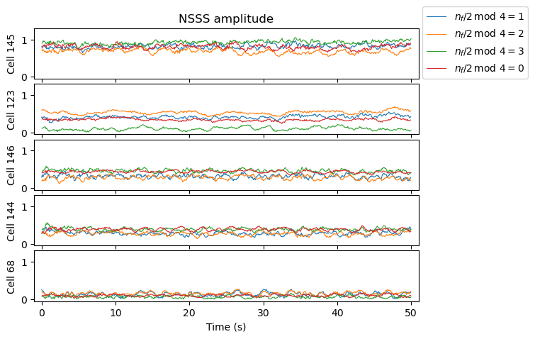
As in the case of the NPSS, all the cells in this recording transmit the NSSS using beaming in a pattern of four beams. Therefore, when studying the NSSS amplitude, I consider separately each case depending on \(n_f/2 \mod 4\). The following plot shows the amplitudes over time for each of the cells detected in the main OFDM grid.
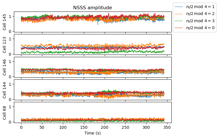
The following shows a zoom to the first 50 seconds of data. We see that by far cell 123 has the largest difference in amplitude between the 4 beams. Without a knowledge of how these beams are supposed to illuminate, it is difficult to interpret this fact.
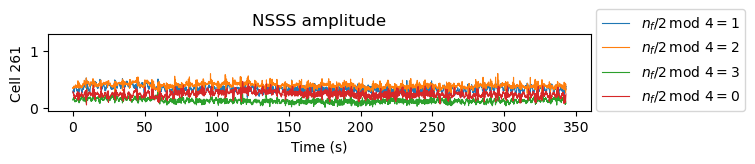
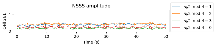
The following two figures show the NSSS amplitude of cell 261. The periodic spikes correspond to strong interference caused by other cells transmitting the SIB-NBs periodically.
NRS
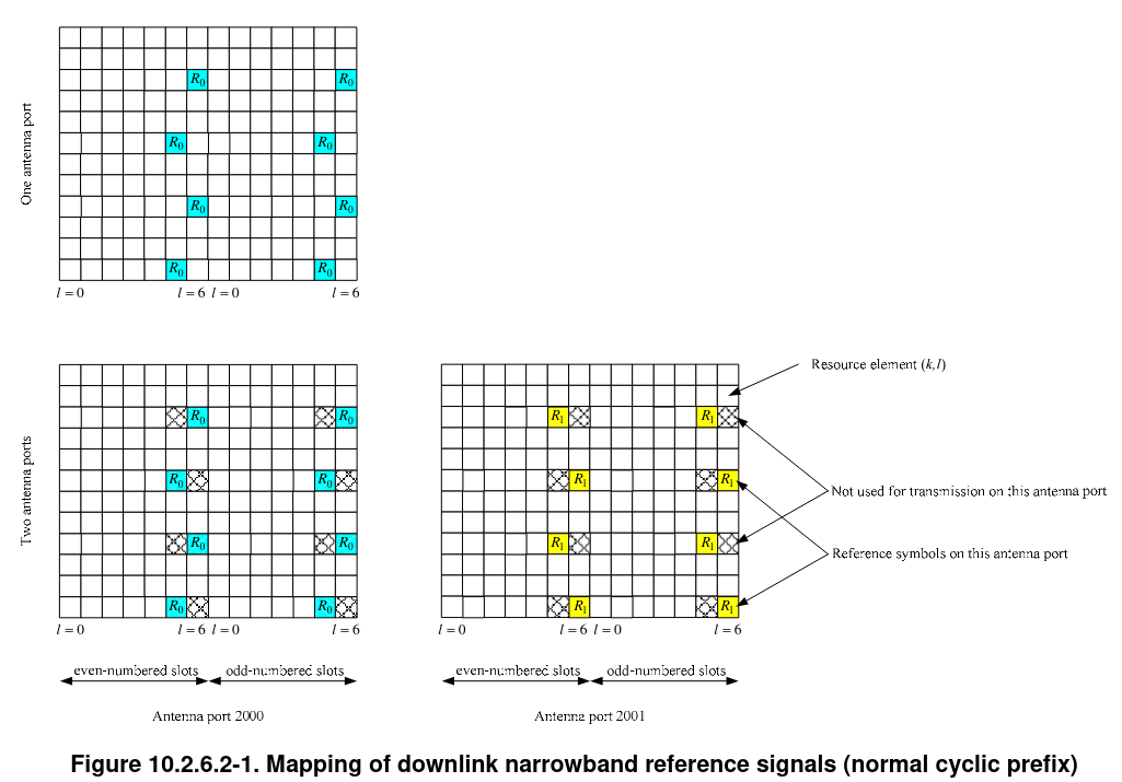
The NRS (narrowband reference signals) are transmitted by the cell in all the subframes except those occupied by the NPSS and NSSS in order to allow receiver to estimate the channel. NB-IoT supports one and two antenna ports in the eNB. These antenna ports are called 2000 and 2001 in order to distinguish them from ports 0, 1, 2, 3 used by the LTE CRS. The NRS appear in some resource elements in the last two symbols of each slot. The subcarriers used by the NRS depend on the cell ID modulo 6, as in LTE. The following figure from TS 36.211 shows the location of the NRS for a cell with cell ID modulo 6 equal to zero.
The NRS sequence is generated in the same way as for the CRS in LTE. It is a QPSK pseudorandom sequence that depends on the slot number, the symbol number, and the cell ID. In LTE, since the UE does not know the cell bandwidth until decoding the MIB-NB, the CRS is generated by assuming the maximum bandwidth, which is 110 resource blocks, to generate the sequence, and then extracting symbols from the middle of the sequence and mapping them to the resource elements that are actually occupied by the cell. The consequence is that for the central part of the cell bandwidth, which is what carries the PBCH, the CRS does not depend on the cell bandwidth. The same is done for NB-IoT by generating the sequence for 110 resource blocks, and taking only the resource block in the middle. This is rather awkward, but once we are aware of this, it does not add any difficulty to the NRS sequence generation.
A UE does not know with certainty if the NB-IoT cell is using one or two ports until it decodes the MIB-NB. As we will see, all the cells in this recording use two ports. Note that for two-port cells, their NRS will use the same resource elements if their cell IDs differ by a multiple of 3. In our case this means that cells 144 and 123 use the same cell IDs, and so their NRS interfere with each other. More concretely, port 2000 of cell 144 uses the same resource elements as port 2001 of cell 123, and port 2001 of cell 144 uses the same resource elements as port 2000 of cell 123. Additionally, cells 146 and 68 use the same cell IDs for each of the ports, since their IDs differ by a multiple of 6.
In order to reduce somewhat the co-channel interference, after wiping off the NRS sequence for each cell, I have performed coherent averaging in intervals of 40 ms. Since the NRS sequence depends on the slot number and symbol number, the sequence only repeats every 10 ms, and coherent averaging for at least 10 ms adds some decorrelation between the different cells, compared to measuring on a symbol by symbol basis.
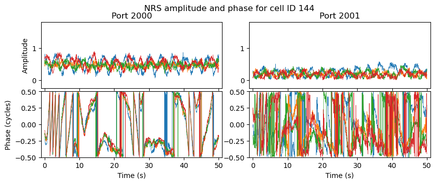
The following plot shows the NRS amplitude and phase for cell ID 145 during the first 50 seconds of the recording. Each of the four subcarriers that can be occupied by the NRS is shown as a different trace in different colour. This allows us to see whether there is any symbol time offset, which would manifest as a phase difference over the subcarriers.
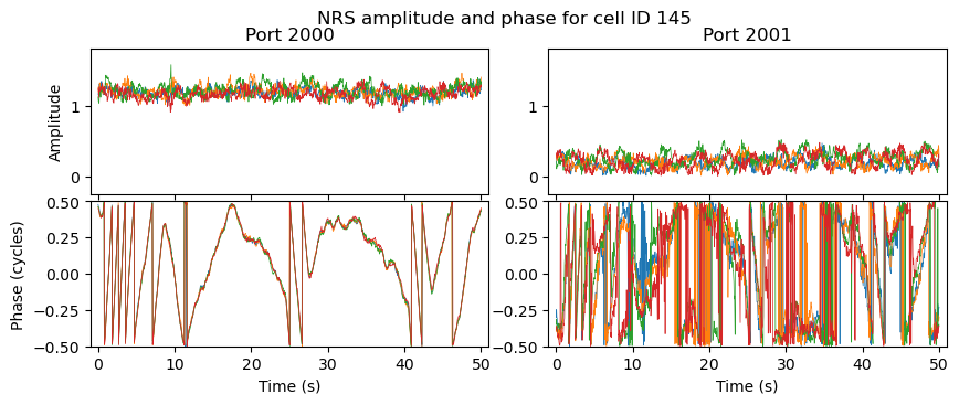
In the amplitude plot we can see that port 2000 is received much more strongly for this cell than port 2001. In the phase plot we can see that the carrier frequency offset is very small. This is because in these plots I have already used the NRS of this cell to get a fine model for carrier frequency offset and symbol time offset versus time. However, judging by the number of phase wraps per second, it looks like there are small frequency jumps. This is better seen in the following plot, which shows the carrier frequency offset estimated from the phase measurements of the port 2000 NRS. There are clearly discrete frequency jumps. While these could be caused by the TCXO of the USRP (it is not the first time that I’ve seen a TCXO do small frequency jumps), I believe that they are caused by the time and frequency disciplination of the eNB, since other eNBs seem to show different jumps (although the SNR of their NRS is not as good as this one to make the same kind of plot).
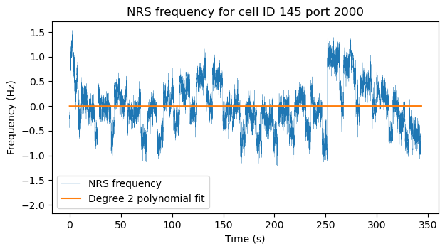
A degree 2 polynomial fit to the frequency error is shown in orange in the plot. This is how I calculate a model for the carrier frequency offset throughout the recording. Since the model has already been calculated and applied, the fit is basically zero.
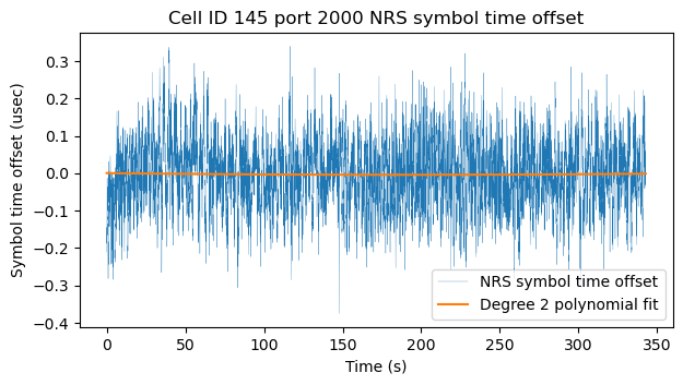
The symbol time offset is measured and modelled in a similar way. The phase difference between the two outermost subcarriers of the cell 145 port 2000 NRS is used to estimate the symbol time offset, and then a polynomial of degree two is fitted to the data as shown in this plot.
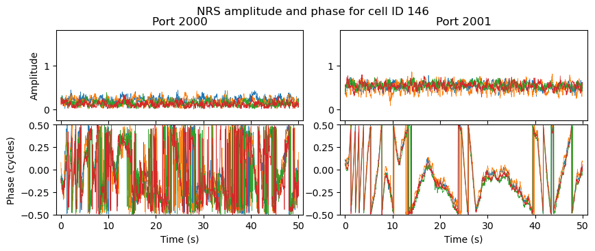
The following plot shows the NRS measurements for cell ID during the first 50 seconds of the recording. For this cell, both ports have approximately the same amplitude. The waviness in the port 2001 amplitude is probably caused by interference with port 2000 of cell 144, which occupies the same resource elements. The interference in port 2000 of cell 123 is not as strong, because as we will see below, port 2001 of cell 144 is received rather weakly. Comparing the phase in this plot and the plot above, it is clear that the frequency jumps are different. For instance, in cell 123 there is a jump around 15 seconds, while such jump is absent in cell 145.
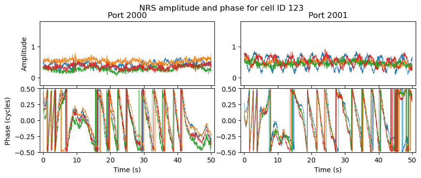
Something else that we can see in this plot is that there is evidence of a symbol timing offset. This makes sense, because cell 123 is probably at a different distance from the receiver compared to cell 145, which is what is used as a reference to zero out the symbol timing offset.
The following two plots show the NRS measurements for cells 144 and 146, which are the other two cells for the three sectors of the same eNB, together with cell 145. In cell 144 port 2000 we can see the interference from cell 123 port 2001. Port 2001 of cell 144 is rather weak, as I mentioned above, and we can see interference caused by port 2000 of cell 123. In cell 146 we see that port 2000 is quite weak, and port 2001 is moderately strong. We can also see that the phase of these cells traces the same path, which makes sense, because they all have a common time and frequency reference.
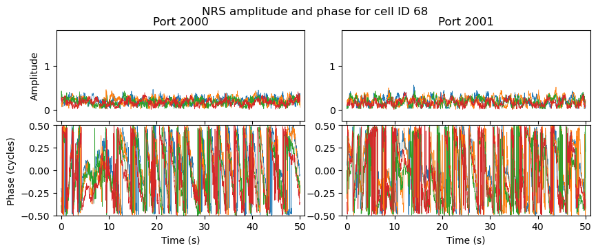
The NRS in both ports of cell 68 is very weak, and it is not clear to which extent we are measuring this cell or contamination from cell 146, whose NRS occupies the same resource elements.
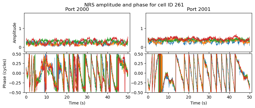
Finally, in cell 261, which uses a different OFDM raster due to the time misalignment with the other cells, we see that both ports have medium to weak amplitude. There is some ripple in the amplitude which is perhaps caused by interference from other cells, or maybe by actual changes in the channel.
NPBCH
The NPBCH (narrowband physical broadcast channel) is used to transmit the MIB-NB (master information block), which carries essential information that a UE needs to know about the cell in order to decode other system information and begin the attach procedure. As shown above, it is transmitted in the first subframe of every radio frame. To avoid potential collisions with other signals that may or may not be present (since the UE does not know yet if they are present), the NPBCH does not use the first 3 symbols of the subframe, and it also avoids the resource elements allocated to 4-port LTE CRS and 2-port NB-IoT NRS. A minor but important detail about this is that when an NB-IoT carrier is used in-band of an LTE carrier, the two carriers may use the same cell ID or a different one. This is important, because it affects the resource elements used by the CRS and NRS. However, because before decoding the MIB-NB the UE does not know the cell ID of the corresponding LTE carrier, the cell ID used to define the CRS resource elements that are avoided by the NPBCH is the same cell ID as the NB-IoT cell ID.
The following figure, taken from the paper A Tutorial in NB-IoT Physical Layer Design shows how the MIB-NB is transmitted in the NPBCH. All the NB-IoT downlink channels that carry data use the same rate 1/3 convolutional coding and rate matching that is used by the PBCH and PDCCH in LTE. In the case of the MIB-NB, the MIB-NB itself is 34 bits. To these 34 bits, a 16-bit CRC is attached. Convolutional coding and rate matching (which in this case amounts to repetition coding) are used to obtain 1600 bits. These are divided into 8 blocks of 200 bits each. Each 200-bit block is transmitted in the NPBCH transmission in a radio frame, but each block is repeated 8 times in 8 consecutive radio frames. Therefore, it takes 64 radio frames (640 ms) to transmit the whole MIB-NB. However, with good enough SNR, the receiver can decode the MIB-NB from any of these NPBCH transmissions. Note that the NPBCH occupies a region of 11×12 resource elements, but avoids 16 CRS resource elements and 16 NRS resource elements, so it actually uses 100 resource elements, which gives 200 bits with QPSK modulation.
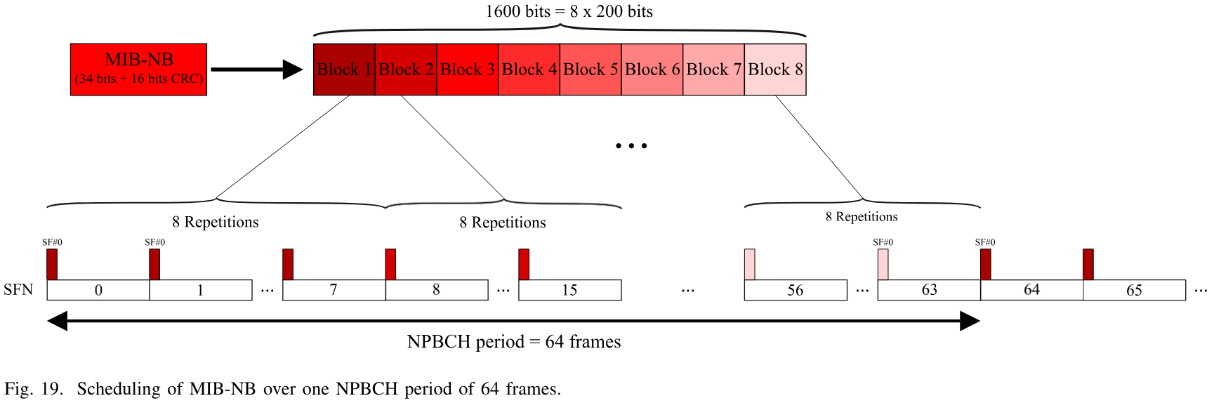
Recall that from detecting the NSSS, the UE has knowledge of the SFN modulo 8. However, to decode the MIB-NB, it needs to know the SFN modulo 64. This is achieved by trial and error decoding the MIB-NB using each of the 8 possibilities.
Another thing that the UE needs to figure out by trial and error is the number of antenna ports. This is encoded by masking the MIB-NB CRC. For one antenna port, the CRC is left as is, while for two antenna ports, the CRC is xor-ed with 0xff. If the cell uses two antenna ports, all the downlink channels that carry data are transmitted using transmit diversity, which I already explained in a post about LTE. The UE needs to take this into account for equalization of the NPBCH. However, in the case in which there is one antenna port and the resource elements that would be occupied by the NRS of port 2001 only contain noise or weak signals (rather than being contaminated by strong interference of other cells), then transmit diversity equalization is essentially identical to single-port equalization. So the UE might get away with assuming that there are two ports to equalize the NPBCH even if there is only one port.
Another thing that we need to take into account to decode the MIB-NB is scrambling. First, there is scrambling applied bit-wise to the 1600-bit codeword, as is common in all the channels that carry data. The scrambling sequence is initialized with the cell ID. Second, there is symbol-level scrambling that is applied to each antenna port after transmit diversity mapping is applied. This symbol-level scrambling is applied to each of the NPBCH transmissions as a block of 100 QPSK symbols. The pseudorandom sequence used for this scrambling depends on the cell ID and the SFN modulo 8, and has a length of 200 bits. Each pair of bits of this sequence is used to select a rotation that is a multiple of 90 degrees that is applied to the corresponding QPSK symbol. Note that this symbol-level scrambling needs to be undone by the receiver before transmit diversity equalization and before any averaging of multiple transmissions of the same MIB-NB block is done. This symbol-level scrambling is something that appeared in release-14 of the 3GPP standards. NB-IoT first appeared in release-13 without this scrambling. Release-13 NB-IoT is also known as LTE Cat NB1, while release-14 NB-IoT is known as LTE Cat NB2. Note that this is a breaking change, since release-13 UEs are not able to decode the MIB-NB and connect to release-14 eNBs. On the other hand, a UE might maintain backwards compatibility with release-13 eNBs by attempting to decode the NPBCH both with symbol-level scrambling and without it.
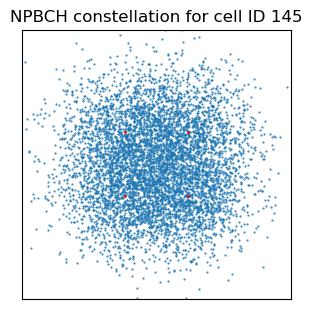
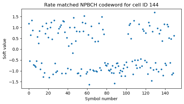
To decode the MIB-NB in our recording, we need to know the SFN modulo 64, which I have guessed by hand, and the fact that two antenna ports are used. We also need to know that these cells use the release-14 symbol-level scrambling. The following plot shows the constellation corresponding to all the NPBCH symbols of the first full MIB-NB transmission in the recording, after symbol-level descrambling and equalization. There is a lot of interference from the other cells, so we cannot recognize the QPSK constellation.
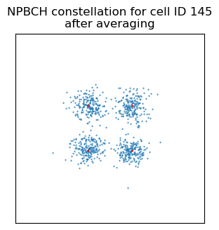
After averaging the blocks of 8 repetitions, we obtain the following constellation, which now is a clean QPSK constellation with very few bit errors. The symbol-level scrambling is what causes this large reduction of co-channel interference, since without it we would be averaging 8 identical repetitions both of the intended cell and of the interfering cells. By applying different symbol-level scrambling to each repetition, the transmissions of each cell decorrelate. For this reason, the symbol-level scrambling is usually called interference randomization.
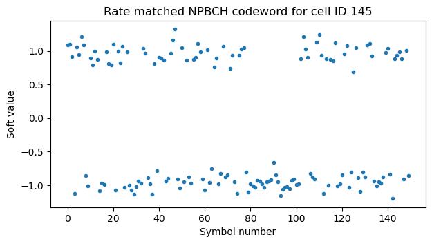
After descrambling, we obtain soft-symbol values for the 1600-symbol codeword. Since Viterbi decoding does not care about the input amplitudes (multiplying the soft symbols by a positive constant yields the same decode), in this post I’m always using soft symbols normalized to an amplitude of one instead of calculating LLRs. Note that this is slightly suboptimal for other signals, because it does not take into account the fact that some symbols can be repeated one more time than others by the rate matching repetition coding.
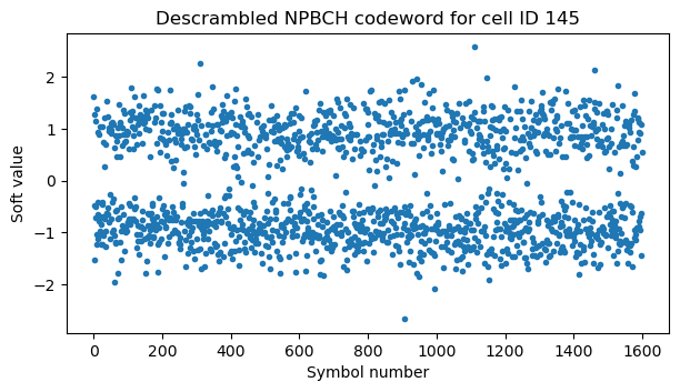
After undoing the rate matching repetition coding, we have no bit errors. Finally the Viterbi decoder can obtain the MIB-NB.
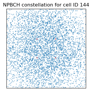
In this case, cell 145 is pretty strong, but it is illustrative to compare with what happens for a weaker cell, such as cell 144. The MIB-NB has a massive coding gain, since 50 bits of information are transmitted over 6400 QPSK symbols. This allows the weaker cells to be successfully decoded even in the presence of very large co-channel interference from stronger cells.
In the constellation after symbol-level descrambling and transmit diversity equalization we cannot recognize anything that resembles QPSK. The values are very large because the interference from other cells dominates and is larger than the signals from this cell.
After averaging the blocks of 8 repetitions, the interference is reduced, but we still cannot see a QPSK constellation.
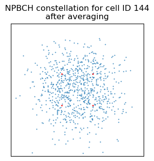
This causes the 1600-bit codeword to look just like noise.
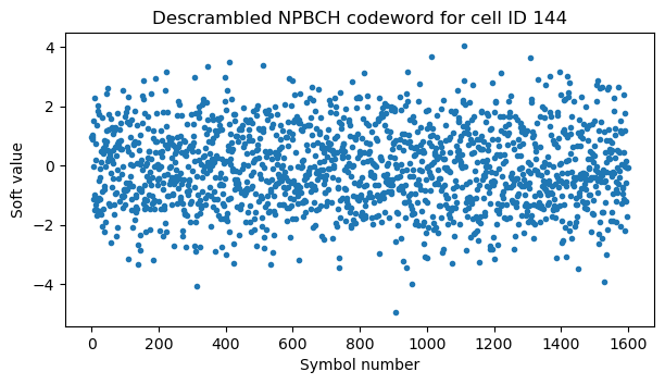
However, after rate matching, there are few bit errors for the Viterbi decoder to fix.
In this recording we can decode all the MIB-NB transmissions from all cells, except for cell 68, for which we can only decode them occasionally.
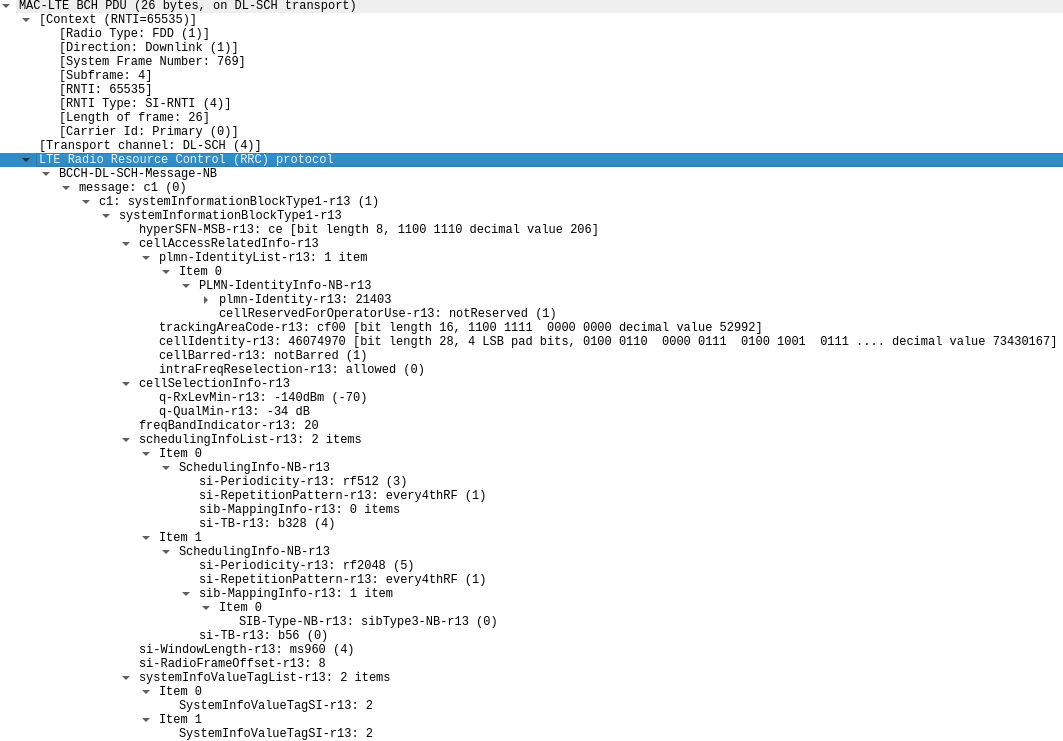
As usual, I’m exporting each decoded message to a PCAP file that can be analysed with Wireshark. The following figure shows the contents of the first full MIB-NB present in the recording, which begins 23 radio frames after the first full radio frame.
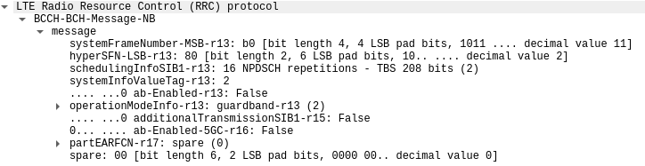
We can see that the 4 MSBs of the SFN are 0b1011. The 6 LSBs of the SFN are known to be zero at the beginning of the MIB-NB transmission. This allows us to calculate the SFN corresponding to the first radio frame in the recording, which is 681.
The Hyper System Frame Number (HFN) is a 10-bit number that counts rollovers of the SFN. In this way, the HFN and SFN together provide a 20-bit counter ticking at 10 ms, which gives a period of about 2.91 hours, which is needed for some of the longer timers used by low duty cycle IoT devices. The 2 LSBs of the HFN are carried in the MIB-NB. In this case they are 10. The remaining 8 MSBs are carried in the SIB1-NB.
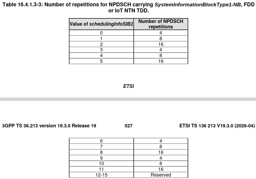
The schedulingInfoSIB1-r13 field determines how the SIB1-NB is scheduled in the NPDSCH. Its value is used with lookup tables that determine the number of NPDSCH repetitions and the transport block size. The number of repetitions is given in Table 16.4.1.3-3 of TS 36.213, shown here.
The transport block size is obtained with the lookup table in Table 16.4.1.5.2-1 in TS 36.213.
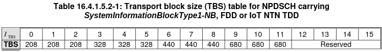
In our case, Wireshark is showing that the scheduling info value is 2, and is parsing it correctly as corresponding to 16 NPDSCH repetitions and a transport block size of 208 bits.
The operation mode indicates that the NB-IoT cell uses guardband mode, and that there is a raster offset of -2.5 kHz. The DC subcarrier of the downlink of an NB-IoT guardband cell must correspond to a frequency on the EARFCN 100 kHz raster with an offset of either -7.5 kHz, -2.5 kHz, 2.5 kHz, or 7.5 kHz. In this case, the IQ recording of the downlink channel was centred at 791.3 MHz (EARFCN 6153), and I had to shift the recording 1234.58 Hz up in frequency in order to get the DC subcarrier aligned DC. Due to the -2.5 kHz offset, this means that the carrier frequency offset was actually 1265.42 Hz (meaning that the signal was 1265.42 Hz higher than expected, corresponding to the receiver LO being 1265.42 Hz lower than expected). This offset corresponds to an error of 1.599 ppm, which is also the sampling frequency error that was measured and corrected using the NRS.
The ab-Enabled and ab-Eanbled-5GC-r16 fields are both set to false, and specify that access barring is disabled for UEs connected to the EPC and to the 5GC respectively.
The other cells have the same values in the MIB-NB, except for the systemInfoValueTag-r13 field, which is different for each cell, as is to be expected. The MIB-NB of cell 261 begins 73.421 ms after the MIB-NB of the other cells, which shows that there is a pretty large time misalignment on this cell.
SIB1-NB
The SIB1-NB is the first system information that the UE decodes after decoding the MIB-NB. It contains basic information about the cell, as well as the scheduling information of the other SIB-NBs. The SIB1-NB scheduling follows a periodicity of 256 radio frames, aligned to SFN equal to zero modulo 256. The transport block of the SIB1-NB is divided into 8 blocks, and each block is transmitted on subframe 4 of every other radio frame in a group of 16 consecutive radio frames. This transmission is repeated a number of times within the 256 frame period, depending on the number of NPDSCH repetitions for SIB1-NB mentioned above. The repetitions are uniformly spread over the 256 frame period, so for 4 repetitions, the repetitions are every 64 radio frames; for 8 repetitions, the repetitions are every 32 radio frames; and for 16 repetitions, the repetitions are every 16 radio frames, in which case all the 16 segments of 16 radio frames in the 256 frame period carry SIB1-NB.
Additionally, the transmissions use an offset that depends on the cell ID and is used to reduce interference between cells by making them transmit at different moments. This offset is defined in Table 16.4.1.3-4 in TS 36.213, which is shown here.
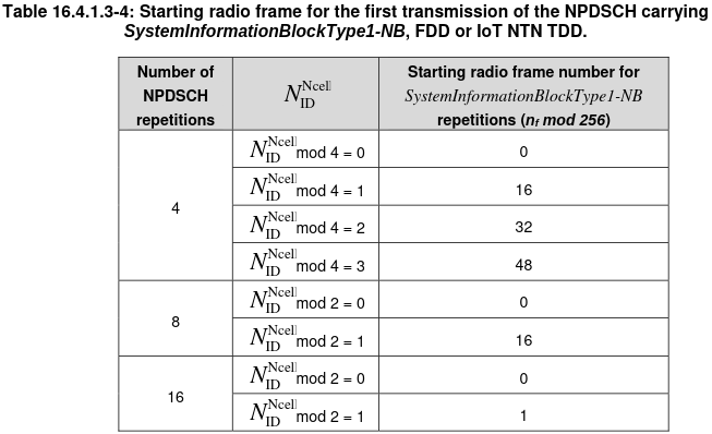
In the case of 4 repetitions, since the repetitions occur every 64 frames and each lasts 16 frames, the possible offsets are 0, 16, 32, and 48, which gives 4 non-overlapping transmission windows. In the case of 8 repetitions, since the repetitions occur every 32 frames and each lasts 16 frames, the possible offsets are 0 and 16, again, giving non-overlapping windows. Finally, in the case of 16 repetitions, the repetitions occur every 16 frames and last 16 frames, so the same strategy cannot be used. What is done in this case is to transmit either on even or odd frames, depending on the cell ID parity. Note that in the cases of 4 and 8 repetitions, the SIB1-NB transmissions are always done in even radio frames, since all the offsets are even and the transmission only occupies every other radio frame.
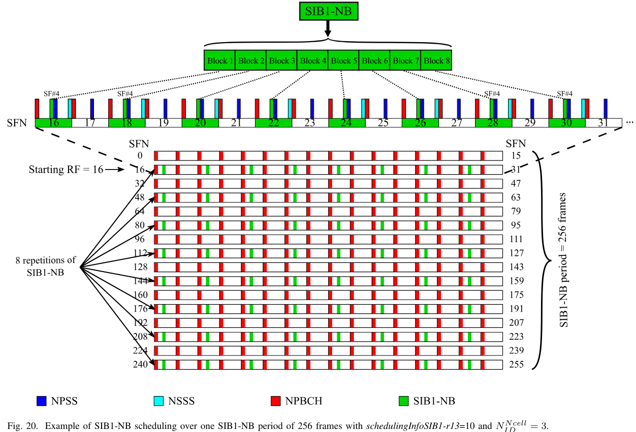
The tutorial paper about the NB-IoT physical layer illustrates the SIB1-NB scheduling with the following example. The number of repetitions is 8, which means the the transmissions happen on every other window of 16 radio frames. The cell ID is odd, which means that the initial frame for the transmission is frame 16 modulo 256. Note that the SIB1-NB is scheduled in subframe 4 of the even radio frames in each active 16-frame window.
In our case, the number of repetitions of the SIB1-NB, which we obtained by decoding the MIB, is 16. This means that all the 16-frame windows are used to transmit the SIB1-NB, and even or odd radio frames are used depending on the cell ID parity. Therefore, we will see large interference between cells that have the same cell ID parity, as they transmit simultaneously.
The SIB-NBs are transmitted in the NPDSCH. In the case of a guardband or standalone NB-IoT cell, all the 14 symbols in a subframe are used by the NPDSCH, so the NPDSCH uses all the resource elements in the subframe except those taken up by the NRS, which are 16 resource elements in this case because the cells use 2 antenna ports.
By having decoded the MIB, we already know the SFN synchronization and the scheduling of the SIB1-NB. Therefore, to decode the SIB1-NB, we first collect the subframes in which the transmissions happen. Then we perform transmit diversity equalization on each of these subframes.
The NPDSCH transport block is scrambled using a pseudorandom sequence that depends on the RNTI (which in this case is the SI-RNTI 0xffff), the cell ID, and the SFN in which the transmission starts. Note that the scrambling sequence for the NPDSCH is different depending on whether the NPDSCH carries the BCCH (which is the case here) or not. Each of the repetitions of the SIB1-NB is scrambled independently, which results in a different scrambling sequence, because they start in different SFNs. The 8 blocks into which the SIB1-NB is divided for transmission are however all part of the same transport block, and they use the same scrambling sequence, whose length matches the length of the concatenation of these 8 blocks. Therefore, to continue decoding the SIB1-NB, we descramble the soft symbols for each of the repetitions with its corresponding scrambling sequence, and then we average all the descrambled repetitions. The channel coding for the NPDSCH is the same as for the NPBCH, so decoding from this point on proceeds identically.
It is worthy to note that a symbol-level scrambling for the NPDSCH that is similar to the symbol-level scrambling for the NPBCH was introduced in TS 36.211 version 14.4.0. However, this functionality is only used with the C-RNTI when enabled by higher layer configuration, for the RA-RNTI, TC-RNTI, P-RNTI and C-RNTI when the NB-IoT carrier si configured with SystemInformationBlockType22-NB (which contains configuration for paging and random access on non-anchor carriers, which is related to NB-IoT multi-carrier operation), and for PUR-RNTI, G-RNTI, SC-RNTI, and CB-RNTI. None of this happens in this recording, so we can ignore this functionality.
In this recording, all the SIB1-NB transmissions of each cell can be decoded successfully, except for cell ID 68, for which decoding is only successful rarely.
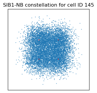
The following figure shows the constellation plot for all the symbols of the first full SIB1-NB transmission of cell ID 145, after transmit diversity equalization. There is interference from other cells, but we can already see that the modulation is QPSK.
After descrambling and averaging the 16 repetitions, the resulting symbols have essentially no bit errors.
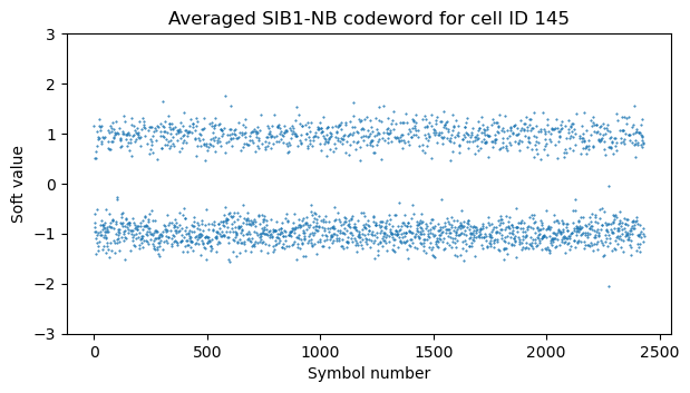
The SIB1-NB has a significant amount of repetition coding applied by rate matching. With 2 antenna ports, there are 1216 QPSK symbols used for the transport block transmission, so we get a total of 2432 bits. For a transport block size of 208 bits, the codeword after encoding with rate 1/3 tail-biting convolutional coding has 696 bits. Therefore, each bit is repeated approximately 3.49 times on average, so after undoing rate matching, the SNR increases even more, and we have a codeword with no bit errors.
In the case of a weaker cell, such as 123, we have very large interference from cell 145 in the SIB1-NB constellation, because both cells transmit at the same time.
After averaging the 16 repetitions the SNR improves but there are still many bit errors. Note that because the pseudorandom sequence of each repetition is different, the intercell interference decorrelates as we average repetitions.
Once we undo rate matching we are left with only very few bit errors that are easily fixed by the Viterbi decoder.
The following image shows the Wireshark dissection of one of the SIB1-NBs decoded for cell 145.
In the SIB1-NB we get the 8 MSBs of the HFN. We also get the cell information. We see that the PLMN identity is 21403, which corresponds to the Orange network in Spain. The frequency band indicator confirms that the band for this cell is B20. The schedulingInfoList-r13, si-WindowLength-r13 and si-RadioFrameOffset-r13 fields contain scheduling information for the SI messages that carry the remaining SIB-NBs. They will be explained in detail in the next section. Something to note is that the first item in the schedulingInfoList-r13 is always assumed to carry the SIB2-NB, plus whatever any other SIB-NBs are explicitly listed, if any. In this case, we see that the first item only carries the SIB2-NB, while the second item explicitly lists the SIB3-NB. Finally, the systemInfoValueTagList-r13 field contains the update version information of each SI message.
All the cells in the recording carry very similar information. The differences are the following. First, the cell identity, for which we have:
- PCI 68, cell identity 0x4484c98
- PCI 123, cell identity 0x46bd696
- PCI 144, cell identity 0x4607496
- PCI 145, cell identity 0x4607497
- PCI 146, cell identity 0x4607498
- PCI 261, cell identity 0x4633396
All these cells are in the same TAC 0xcf00.
Second, there are two different configurations for the SI messages. Cells 144, 145, 146 transmit the SIB2-NB and SIB3-NB in separate SI messages as shown above. In contrast, cells 68, 123 and 261 transmit the SIB2-NB and SIB3-NB in the same SI message, which is scheduled as shown here.
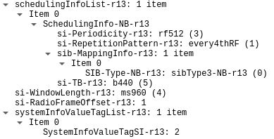
The si-RadioFrameOffset-r13 parameter is different for each of the cells. This causes the SI messages to be transmitted at different times, in order to avoid interference. The SystemInfoValueTagSI-r13 values are also different for each cell.
SI messages
The remaining SIB-NBs are transmitted in SI messages in the NPDSCH which are scheduled by the information in the SIB1-NB. The way scheduling works is as follows. Each SI message has a corresponding entry in the SIB1-NB scheduling information list. This entry defines a time window in which the SI message can be transmitted. The length of these windows is the same for all the SI messages, and is given by the si-WindowLength-r13 parameter, which in our case is 960 ms. Each window appears with a potentially different periodicity, given by the si-Periodicity-r13 field. In our case, this is 512 radio frames (5.12 seconds) for the first SI message, and 2048 radio frames (20.48 seconds) for the second SI message (in the cells that have it). The window for the first SI message begins at the SFN indicated by the si-RadioFrame-Offset-r13, which is a small integer used to avoid having all cells transmit simultaneously, and then reappears according to its 5.12 second periodicity. The second window begins at the SFN given by the si-RadioFrame-Offset-r13 plus 96 radio frames, so that the windows for the two SI messages are adjacent when they appear together (once every 4 occurrences of the first SI message, due to their different periodicities).
Within each window, the SI message is repeated multiple times according to the si-RepetitionPattern-r13 field. In this case, the value of this field is every 4 radio frames. This means that the SI message is repeated every 4 radio frames until the window ends. The SI messages are transmitted in the NPDSCH, in subframes not allocated to the NPBCH, NPSS, NSSS, and SIB1-NB. The length of the SI message transmission depends on the transport block size. For transport block sizes of 56 and 120 bits, only 2 subframes are used. These are always subframes 1 and 2 in the radio frame, since subframe 0 is always taken by the NPBCH, but subframes 1 and 2 never used by the other signals. For larger transport block sizes, the transmission uses 8 subframes. Which subframes are used depends on whether subframe 4 needs to be skipped because it is taken up by the SIB1-NB, and whether subframe 9 needs to be skipped because the radio frame is even and the subframe is taken up by the NSSS. Note that depending on whether these happen, the SI message transmission might extend to the first subframes of the next radio frame, or finish in subframe 9 of the radio frame in the best case.
The following figure shows an example of SI message scheduling taken from the tutorial paper about the NB-IoT physical layer. In this example there are two SI messages having periodicities of 128 and 512 radio frames respectively. The window length is 480 ms. The first SI message has a transport block size larger than 120 bits and is repeated every 2 radio frames. The second SI message has a transport block size smaller or equal than 120 bits and is repeated every 4 radio frames. The radio frame offset is 7.
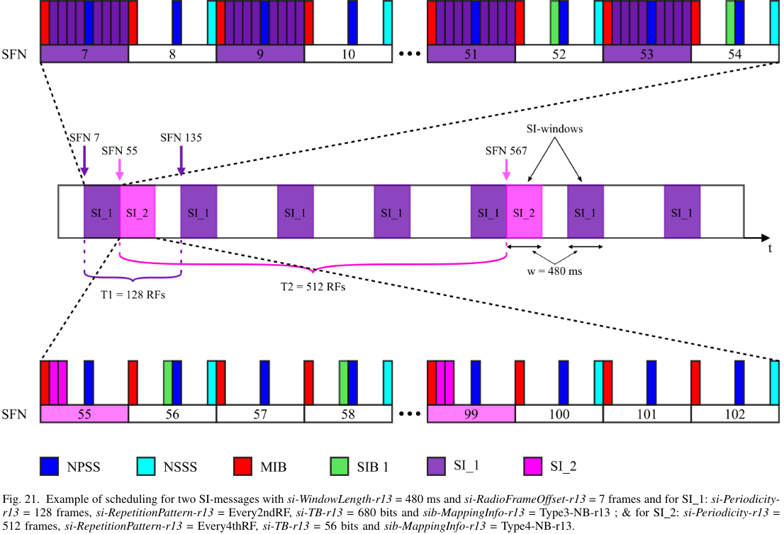
Note that in this case the SI messages do not need to avoid the SIB1-NB and NSSS transmissions, because the SI messages are always transmitted in odd frames and the SIB1-NB and NSSS are transmitted in even frames. However, in the recording there are cases in which the SI messages are transmitted in frames that carry the SIB1-NB and/or NSSS, since some cells have even radio frame offsets for the SI message scheduling and because the SIB1-NB uses 16 repetitions, it can appear in odd radio frames depending on the cell ID parity.
Decoding the SI messages is very similar to decoding the SIB1-NB. The only difference is the scheduling. To decode an SI message transmitted in a given window, we select the subframes for each repetition, perform transmit diversity equalization, descramble each repetition, average all the repetitions, and perform FEC decoding.
As usual, we can decode all the SI message transmissions for all the cells, except for cell 68, for which we can decode successfully only rarely.
Here is another good example of how repetitions allow us to decode successfully the SI messages even if there is strong interference from other cells. Since cell ID 261 is not synchronized to the rest of the cells, its SI message transmissions suffer interference from other signals transmitted by stronger cells. In the constellation we can see that the effects of this interference are pretty large.
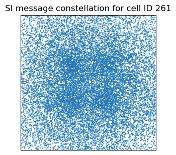
Once we average all the 24 repetitions that happen in the 960 ms window, we see something that looks much better, but still there is evidence of time-dependent interference.
After undoing the repetition coding from rate matching we get something quite reasonable that the Viterbi decoder can decode correctly.
SIB2-NB
The SIB2-NB contains a lot of fields. The following shows the Wireshark dissection of a SIB2-NB for cell ID 145. The nprach-Config-r13 and npush-ConfigCommon-r13 sections are collapsed and they will be shown below in more detail.
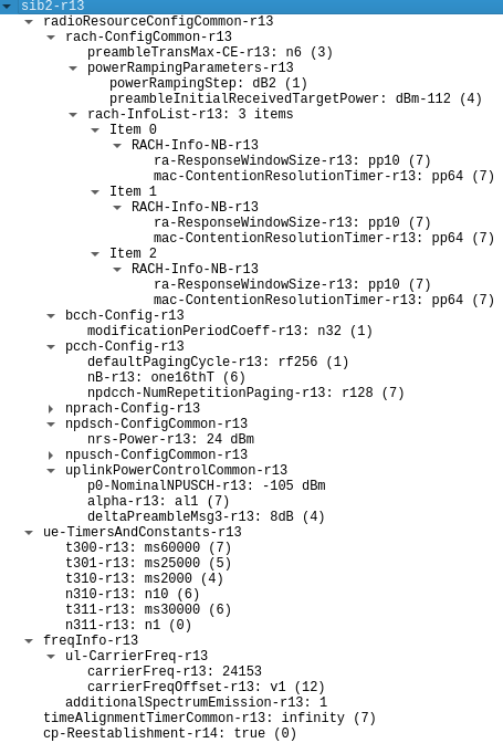
On the rach-ConfigCommon-r13 section we have configuration parameters for the random access channel. The modificationPeriodCoeff-r13 field in bcch-Config-r13 gives the modification period of the system information, as a multiple of the paging cycle. In this case the multiple is 32, and the paging cycle is 256 radio frames. Therefore, the modification period is 8192 radio frames, or 81.92 seconds. I will come back to the PCCH configuration below when I explain how to decode paging messages.
The contents of the NPRACH configuration section are shown below. In NB-IoT, NPRACH is done with an MFSK signal produced by groups of 5 OFDM symbols of duration 266.7 usec that generate a CW carrier, with a cyclic prefix for the whole group. The cyclic prefix duration is either 66.7 usec or 266.7 usec, and is indicated in the nprach-CP-Length-r13 field.
The rsrp-ThresholdsPrachInfoList-r13 defines three different coverage enhancement levels in terms of the NRSRP measured by the UE. Each coverage enhancement level uses a different NPRACH configuration, as indicated by the nprach-ParametersList-r13 field. In this case, the three levels are CE0, which is anything above -110 dBm, CE1, which is anything between -120 dBm and -110 dBm, and CE2, which is anything below -120 dBm. For reference, keep in mind that 300 K noise temperature in 15 kHz bandwidth is -132 dBm.
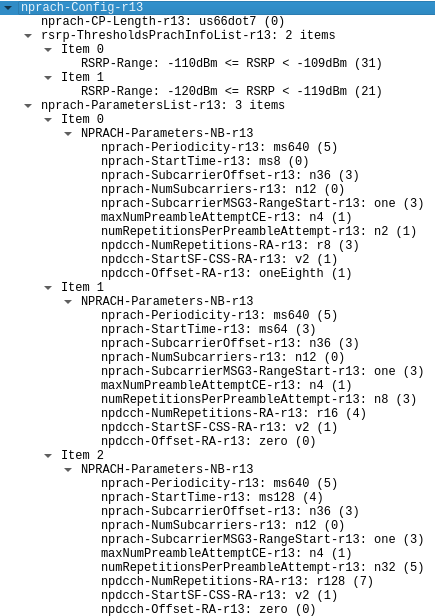
The goal of the three coverage enhancement levels is to configure UEs that have worse coverage with a longer NPRACH that is easier for the eNB to detect, and to configure the NPDCCH that carries the reply from the eNB with more repetitions so that it is easier for the UE to decode it. In this case we see that the three configurations differ in the following fields:
numRepetitionsPerPreambleAttempt-r13, which indicates how many times the NPRACH sequence, formed by 4 tones of 5 symbols each, is repeatednpdcch-NumRepetitions-RA-r13, which indicates the maximum number of repetitions used in the NPDCCH transmission that schedules the corresponding RAR (random access response) from the eNBnpdcch-Offset-RA-r13, which gives a time offset for NPDCCH transmissions and will be explained it detail belownprach-StartTime-r13, which gives a time offset to the transmissions of the different CE levels to avoid them from overlapping and causing a strong UE to interfere with a weaker UE
In the npdsch-ConfigCommon-r13 section we have the nrs-Power-r13 field, which indicates that the NRS EPRE (energy per resource element) is 24 dBm. This means that the total power of the cell is 34.8 dBm, which is 3 W.
The npush-ConfigCommon-r13 section contains a field ack-NACK-NumRepetitions-Msg4-r13 that indicates the number of repetitions that are to be used in the NPUSCH format 2 reply to the Msg4 during the RRC connection procedure (Msg4 is the message carrying the RRCConnectionSetup message sent by the eNB). A different value is used for each CE level. We will see this below in more detail, but it turns out that the first time that the V16 beacon connected to the RRC to attach the network, it used CE0, which in cell 261 is configured with 2 NPRACH preamble repetitions and 2 NPUSCH repetitions for Msg4 (there are some small differences between the configuration of cells 145 and 261 that I will summarize below). The next times that the V16 connected again to the RRC to transmit another message it used CE1, which in cell 261 is configured with 8 NPRACH preamble repetitions and 2 NPUSCH repetitions for Msg4. I had already noticed this difference while studying the uplink recording. The difference between the NPRACH lengths can be seen in the waterfalls in the uplink post. This also causes some differences in other RRC configuration parameters. I am unclear on why the UE uses CE1 for the RRC connections after the first one, since it always reports an NRSRP of around -95 dBm in the RRC connection setup complete message.
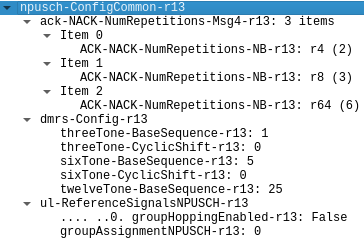
SIB2-NB NPUSCH configuration for cell ID 145 dissected in Wireshark
The dmrs-Config-r13 section defines the sequences that are used in the NPUSCH DMRS. However, these are set to their default parameters (“If not signalled by higher layers”) defined in Section 10.1.4.1.2 of TS 36.211 as the cell ID modulo 12 for the 3-tone sequence, the cell ID modulo 14 for the 6-tone sequence, and the cell ID modulo 30 for the 12-tone sequence. For instance, for cell ID 145 these default values are 1, 5, and 25 respectively, which match the contents of the SIB2-NB. The same happens for the other cells. This explains why I could use these default values when decoding the uplink in the previous post. The cyclic shifts for the 3-tone and 6-tone sequences are set to zero, which is also what I had assumed and checked in that post. Group hopping for the DMRS is disabled, which is also something I had verified in the uplink post.
The uplinkPowerControlCommon-r13 section contains parameters that define the uplink power used by the UE according to the rules in section 16.2.1.1.1 of TS 36.213. The values used by this cell mean that the UE should aim to achieve a received power of -105 dBm per each 15 kHz on the eNB, using the nrs-Power-r13 value and its NRSRP to estimate path loss. There are additional values that are used to configure powers for each of the messages in the random access procedure.
The ue-TimersAndConstants-r13 section indicates some configuration values for the UE MAC, and I will not analyse them in detail.
The freqInfo-r13 section contains the information about the corresponding uplink carrier. We see that the EARFCN is 24153, which corresponds to the frequency 832.30 MHz in the uplink of the B20 band, as expected. We also see that there is a carrierFreqOffset-r13 value of v1. The meaning of this field is defined in Section 5.7.3F of TS 36.101. For FDD, the offset \(\mathrm{M}_{\mathrm{UL}}\) can be an integer between -10 and 9 (both included), and corresponds to 5 kHz units with respect to the raster frequency indicated by the EARFCN. In this case, the value of v1 means \(\mathrm{M}_{\mathrm{UL}} = 1\), so there is a 5 kHz offset in the uplink frequency. In the post about the uplink recording I didn’t take this offset into account and found that the IQ data had to be shifted down by 6310 Hz to get the uplink waveform at baseband, with additional corrections of a few 10s of Hz depending on the transmission (this already takes into account the fact that the OFDM carriers of the waveform are shifted by 7.5 kHz). Now that we know that the uplink carrier has a 5 kHz offset, it turns out that the uplink frequency was only 1310 Hz higher than it should. This matches the 1265.42 Hz carrier frequency offset that I have measured in the downlink, since scaling 1265.42 Hz by 832.3 MHz / 791.3 MHz gives 1330 Hz. The additionalSpectrumEmission-r13 field can be used to require UEs to comply with stricter emission mask requirements, but I believe that the value 1 signals the default mask given in Section 6.6.2F.1 of TS 36.101.
Finally, the timeAlignmentTimerCommon-r13 field indicates for how long a UE can consider a given time advance value valid, and the cp-Reestablishment-r14 field set to true signals that the UE is allowed to trigger an RRC connection re-establishment without having activated AS security.
The SIB2-NBs of the cells decoded in this recording contain only small differences. Cells that transmit the SIB2-NB and SIB3-NB in different messages are all configured in the same way as cell 145 (except for the NPUSCH DMRS sequences, which depend on the cell ID). Cells that transmit the SIB2-NB and SIB3-NB in the same message have the following differences with respect to cell 145 (in addition to the NPUSCH DMRS sequences):
- The NPRACH scheduling is different. The periodicity and start times for the 3 CE levels are 320 ms period, 8 ms offset for CE0; 640 ms period, 512 ms offset for CE1; 1280 ms period, 128 ms offset for CE2. In cell 145 the periodicity is always 640 ms, and the offsets are 8, 64, 128 ms for CE0, CE1, CE2 respectively.
- The NPUSCH format 2 repetitions for Msg4 are 2, 2, 32 for CE levels CE0, CE1, CE2 respectively, while for cell 145 they are 4, 8, 64.
- The following additional fields are included in the SIB2-NB:
servingCellMeasInfo-r14: true. This indicates that the serving cell idle mode measurement reporting in the RRC connection setup complete and similar messages is allowed. This is something that I already observed in the two posts I wrote about the uplink. I remarked that the RRC connection setup complete message with cell 261 contained ameasResultServCell-r14section that indicated an NRSRP of -95 dBm (5 dB above the CE0/CE1 boundary), and an NRSRQ of -11 dB, while this section was absent in the RRC connection setup complete message with cell 145.cqi-Reporting-r14:true. This indicates that the downlink channel quality reporting in the RRC connection request and similar messages is allowed. This is also something that I had observed in the posts about the uplink. I mentioned that thecqi-NPDCCH-r14field in the RRC connection request message contained a value indicating a target of 4 NPDCCH repetitions in the recording in which the V16 beacon connected to cell 261, while it contained a value of “no measurements” in the recording in which the V16 beacon connected to cell 145.
SIB3-NB
The SIB3-NB is quite simple, as it only contains a few values for the cell re-selection criteria. The values are the same for all the cells in the recordings.
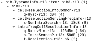
SIB3-NB for cell ID 145 dissected in Wireshark
The rules that use these values are in TS 36.304. Section 5.2.4.2a contains the measurement rules for cell re-selection. The values above mean that if the NRSRP of the serving cell is 58 dB or more above the minimum level of -128 dBm, then the UE may choose not to do intra-frequency measurements for re-selection. If the NRSRP of the serving cell is 18 dB or more above -128 dBm, then the UE may choose not to do inter-frequency measurements (but here there are no inter-frequency measurements to do, because the only band that has NB-IoT in Spain is B20). The re-selection criteria for moving to another cell is that it needs to have at least 4 dB better NRSRP than the serving cell for a period of 6 seconds.
NPDCCH
The NPDCCH carries control information. All the NPDSCH transmissions except those carrying system information are scheduled by the NPDCCH. Additionally, the NPDCCH is used to send uplink grants. Like the NPDSCH, the NPDCCH can occupy the subframes that are not used by other signal, including system information NPDSCH transmissions.
The NPDCCH uses the concept of NCCEs (narrowband control channel elements) to allow simultaneous transmission of up to two independent NPDCCH messages. An NCCE is formed by 6 consecutive subcarriers, so the NB-IoT cell is divided into NCCE0, which is the lower 6 subcarriers, and NCCE1, which is the upper 6 subcarriers. An NPDCCH transmission is said to use format 0 if it occupies one NCCE, and format 1 if it occupies both NCCEs. Format 0 can only be used on the UE-specific search space, which is presented below, and only when the NPDCCH is repeated in just one subframe. All the NPDCCH transmissions that I have seen in this recording use format 1, which makes sense, because no cell is addressing multiple UEs simultaneously at any point, and additionally they are all repeated over multiple subframes.
The size of an NPDCCH transport block depends on the DCI message that is carried. The transport block is encoded using convolutional coding in the same way as the NPDSCH, and mapped to the available resource elements in a subframe, which in the case of a guardband/standalone cell with 2 antenna ports are 152 QPSK resource elements for format 1, and 76 QPSK resource elements for format 0. Transmit diversity is used.
An NPDCCH transmission can be repeated in multiple consecutive subframes, skipping over subframes allocated to the NPBCH, NPSS, NSSS, and system information NPDSCH. Each of these subframes is scrambled independently, and the scrambling sequence is reset every 4 repetitions, which means that each set of 4 repetitions has the same scrambling and therefore identical symbols. The scrambling sequence depends on the subframe number and the cell ID.
As in LTE, the NPDCCH transport block is appended with a CRC-16, and the CRC is XOR-ed with the RNTI in order to support blind decoding. There are different search spaces for blind decoding of the NPDCCH:
- The Type1 common search space is used to send paging and direct indication information. It only uses NPDCCH format 1, and the DCI type is N2, which has a size of 15 bits.
- The Type2 common search space is used during the RRC connection process, before a UE-specific search space is configured. It only uses NPDCCH format 1, and it can carry DCI types N0 and N1. DCI type N0 carries an uplink grant, and DCI N1 caries NPDSCH scheduling. These DCI types have a base size of 23 bits, but they can be larger due to the addition of some optional fields, as we will see below.
- The UE-specific search space is used after it has been configured during the RRC connection. It can use NPDCCH format 0 and format 1. Like the Type2 common search space, it carries DCI types N0 and N1.
I will explain these search spaces and their relevant parameters in more detail when we decode NPDCCH transmissions in each of these spaces.
As in the case of the NPDSCH, in version 14.4.0 of TS 36.211, a symbol-level scrambling was introduced for the NPDCCH. This symbol-level scrambling is only used in the same situations as for the NPDSCH, so we can ignore it in this recording.
Paging NPDCCH
Paging transmissions are an easier target to decode. Because all the cells belong to the same tracking area, paging is transmitted simultaneously by all the cells. That means that it is relatively easy to locate these NPDCCH transmission by their power during the recording analysis and decode them by hand instead of having to do blind decoding with the right parameters.
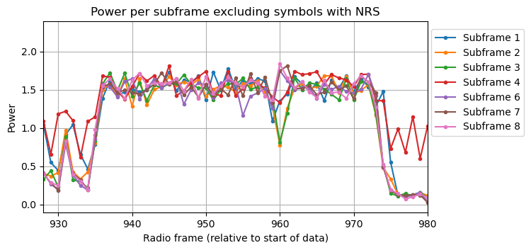
The following plot shows a measurement of the power of each subframe in each radio frame, excluding OFDM symbols that carry NRS resource elements. Subframes 0, 5 and 9 are not shown because they always carry the NPBCH, NPSS and NSSS (only in even radio frames) respectively. The other subframes are only active when there are NPDCCH or NPDSCH transmissions, so this kind of plot is a good way to detect these transmissions. Subframe 4, shown in red, always has power, because it carries the SIB1-NB in every other frame depending on the cell ID parity, and we have both even and odd cell IDs. The other subframes are quiet most of the time.
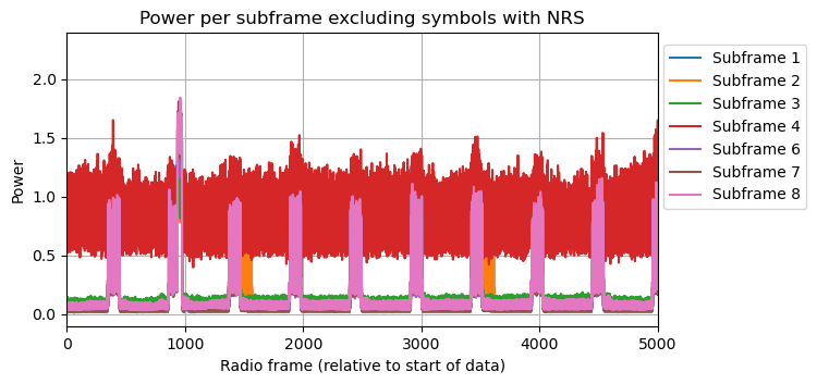
We can see periodic transmissions in pink that correspond to the SIB2-NB SI message. There are also some periodic transmissions in orange which correspond to the SIB3-NB SI message (for those cells that transmit it separately). These are orange because the SI message is short, so it only occupies subframes 1 and 2. Additionally, we can see a shorter strong transmission slightly before radio frame 1000. This is a paging transmission. In this case, the paging transmission overlaps with the SIB2-NB transmission, so it is slightly tricky to decode it correctly, because we need to account for the subframes used by the SIB2-NB when selecting the subframes that are used for the paging NPDCCH and NPDSCH.
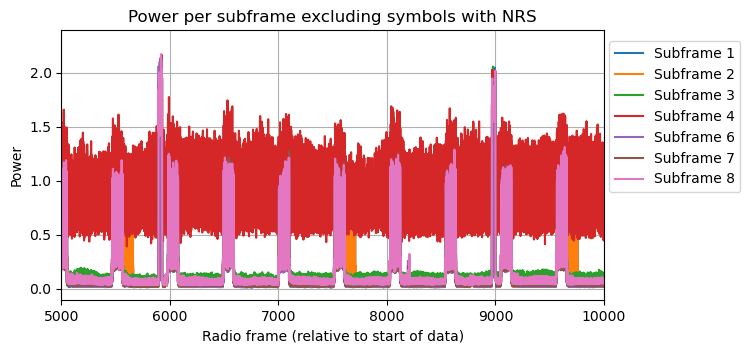
The next plot shows the power in the next 50 seconds of the recording. Now we see two paging transmissions that do not overlap with the SI messages. These are easier to decode.
The following two plots show a detail of the first two paging transmissions in the recording. The second one is easier to understand, because there is no SI message being transmitted at the same time.
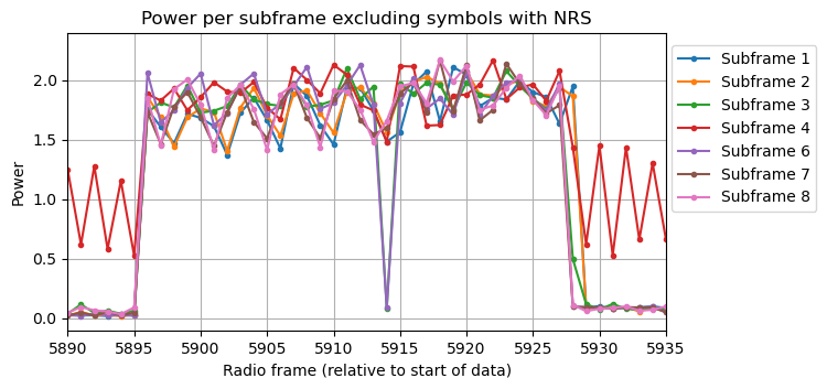
In the second plot we can see two distinct transmissions with a gap between them. These are the NPDCCH transmission and the NPDSCH transmission. There is always a gap of 4 subframes between the end of an NPDCCH transmission containing downlink scheduling and the corresponding NPDSCH transmission.
Here we can see the 4-subframe gap in the Inspectrum waterfall, at the 59.15 second mark. The NPDCCH finishes in subframe 2, then we have subframe 3 empty (with only NRS), subframe 4 carries the SIB1-NB, subframe 5 carries the NPSS, subframe 6 is also empty, and the NPDSCH begins in subframe 7.

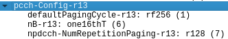
The PCCH configuration in the SIB2-NB is shown again here for convenience. The npdcch-NumRepetitionPaging-r13 field indicates the maximum number of repetitions that can be used for a paging NPDCCH transmission, that is, how many subframes can be occupied by such transmission. In this case, the value is 128 subframes. The other fields determine the PCCH scheduling, and I will come back to them later. For the moment we don’t need to use them, since we are detecting PCCH transmission manually by looking at their power.
The subframe in which the paging NPDCCH transmissions start can be measured in the power plots above. We also need to know how many subframes are used for the transmission. The value in the npdcch-NumRepetitionPaging-r13 field is technically a maximum, but in the typical case this maximum is used. In fact, TS 36.311 describes this value as “estimate of the required number of repetitions for NPDCCH”. Because we can see the gap between the NPDCCH and the NPDSCH in the power plot, we can confirm that in fact the NPDCCH length is 128 subframes, instead of any of the other possible lengths, which I will list below. To decode an NPDCCH transmission, we collect 128 subframes starting at this location and skipping over subframes used by other signals. We perform transmit diversity equalization for each subframe. Then the soft symbols for each subframe are descrambled, taking into account that each group of 4 consecutive repetitions uses the same scrambling sequence. Finally, all the subframes are averaged, and channel decoding is done. These NPDCCH transmissions carry DCI N2 format, so the transport block size is 15 bits. The CRC-16 is XOR-ed with the P-RNTI 0xfffe.
The next figure shows the constellation for the first NPDCCH transmission of cell 145. As usual, there is a lot of interference from other cells.
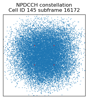
After averaging and descrambling the 128 repetitions, the interference from other cells decorrelates and we get very few bit errors.
The coding rate on NPDCCH messages is pretty high. Each subframe carries 304 bits, but the message including CRC is only 31 bits long. Therefore, the rate matching algorithm does a lot of repetition coding (an average of 3.27 repetitions per bit) and we further increase the SNR when undoing rate matching. The codeword now has no bit errors.
In comparison, if we look at a weaker cell, such as cell 123, we see that the constellation has massive interference from stronger cells such as cell 145. Note that the transmission for cell IDs 123 and 145 begin at different subframes. The NPDCCH transmission is scheduled in the same starting subframe in all the cells, as we will see below. However, because an SI message transmission overlaps with this paging transmission, each cell must avoid its own SI message transmissions, which happen in different frames. Therefore, there is a radio frame of difference in the actual starting subframes of this NPDCCH transmission.
After averaging the 128 repetitions we still have a lot of bit errors.
Even when rate matching is undone, the convolutional codeword doesn’t look great. However the Viterbi decoder can correctly decode it.
All the paging NPDCCH transmissions in the recording can be decoded successfully, except for a few transmissions from cells 123, 144 and 261, and all the transmissions of cell 68.
The DCI N2 format is defined in Section 6.4.3.3 of TS 36.212. The fields are different depending on whether the CRC is scrambled by the P-RNTI or the SC-RNTI. Here I only speak about the P-RNTI case. The first bit is a flag that indicates whether the DCI carries paging (flag value 1) or direct indication (flag value 0). Direct indication is a mechanism to notify UEs about changes to system information or alerts (ETWS and CMAS). The contents of the direct indication information for NB-IoT are defined in Section 6.7.5 in TS 36.331. There are not direct indication messages in this recording, so I will not go into further details.
When the DCI carries paging, the remaining fields are organized as follows:
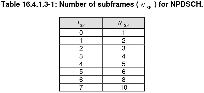
- Resource assignment. 3 bits. Contains the index \(I_{\mathrm{SF}}\) that indicates the number of subframes \(N_{\mathrm{SF}}\) used by the corresponding NPDSCH transmission according to the following table from TS 36.213.
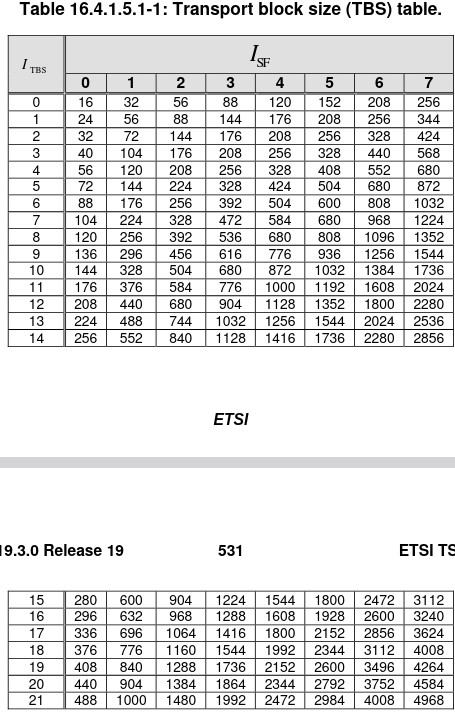
- Modulation and coding scheme. 4 bits. Contains the index \(I_{\mathrm{TBS}}\) that together with \(I_{\mathrm{SF}}\) determines the transport block size according to the following table.
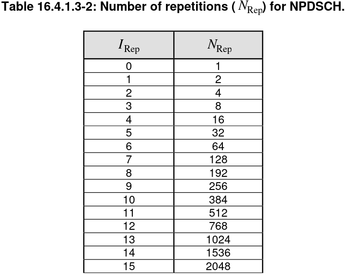
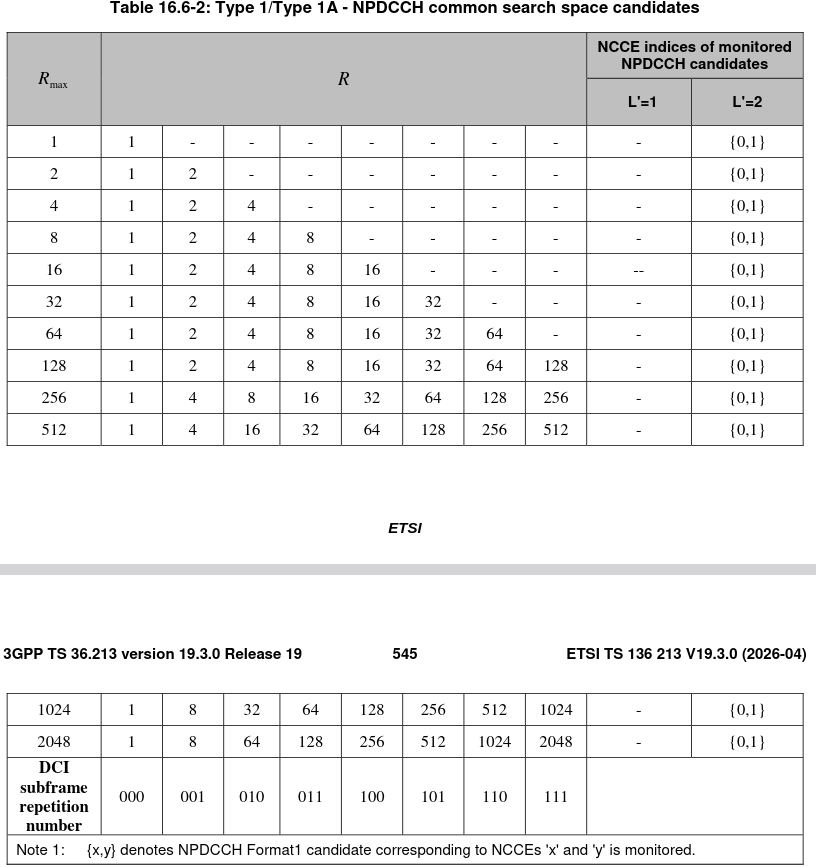
- Repetition number. 4 bits. Contains the index \(I_{\mathrm{Rep}}\) that indicates the number of repetitions of the NPDSCH transmission according to the following table.
- DCI subframe repetition number. 3 bits. The value
npdcch-NumRepetitionsPagingincluded in the SIB2-NB indicates \(R_{\mathrm{max}}\), the maximum number of repetitions that can be used by the NPDCCH transmission. According to this maximum, the possibilities for the actual number of repetitions \(R\) is shown in the following table. A UE needs to attempt blind decoding for each of these possible values of \(R\). It will typically do so incrementally, as new subframes arrive. However, because these are all repetitions of the same message, if the SNR is good the UE can decode successfully using fewer repetitions than \(R\). Because the start of the corresponding NPDSCH transmission is defined in terms of the end of the NPDCCH transmission, the UE needs to confirm the exact value of \(R\) that was used. This is encoded in this DCI subframe repetition number field.
All the paging NPDCCH transmissions in all the cells contain identical DCI N2 messages. The following contains the parsed values of the first such DCI in cell 145.
Subframe 9360
==============
NcellID = 145
DCI format N2
-------------
- flag = 1 (paging)
- I_SF = 2 -> N_SF = 3
- I_TBS = 0 -> TBS = 56
- I_rep = 5 -> N_rep = 32
- DCI subframe repetition number = [1, 1, 1]
We can see that the corresponding NPDSCH transmission occupies 3 subframes, is repeated 32 times, and the transport block size is 56 bits. According to the table above, the DCI subframe repetition number of 0b111 together with \(R_{\mathrm{max}} = 128\) gives \(R = 128\), indicating that the actual number of repetitions for these NPDCCH transmissions is 128.
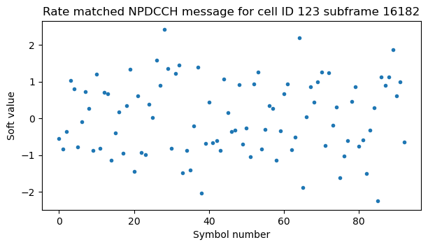
NPDSCH
The NPDSCH is transmitted and encoded in a similar way to the NPDCCH. There is no concept analogous to the NCCEs, so the NPDSCH always occupies the 12 subcarriers. Like the NPDCCH, the NPDSCH is transmitted in consecutive subframes, skipping over those subframes used by the NPBCH, NPSS, NSSS and system information. There is a mechanism that allows including gaps in very long NPDSCH transmissions, but this mechanism is not used in the recording. The main difference between the NPDSCH and the NPDCCH is that the NPDSCH length can be more than one subframe. This interplays with repetitions and scrambling in the following way.
Each subframe of the NPDSCH is transmitted either 4 times in a row or the number of NPDSCH repetitions, whatever is smaller. After all the subframes of the NPDSCH have been transmitted, if there are remaining repetitions (because the number of NPDSCH repetitions is greater than 4), then the process begins again by transmitting each subframe at most 4 times in a row. This continues until all the repetitions have been done. Since the number of NPDSCH repetitions \(N_{\mathrm{Rep}}\) according to the table shown above is either 1, 2, or a multiple of 4, what happens in practice is that either the NPDSCH is transmitted without any repetitions if \(N_{\mathrm{Rep}} = 1\), or each subframe is repeated 2 times in a row if \(N_{\mathrm{Rep}} = 2\), or each subframe is repeated 4 times in a row, and the whole sequence of \(4 N_{\mathrm{SF}}\) subframes is repeated \(N_{\mathrm{Rep}}/4\) in any other case.
Each of the consecutive repetitions of the same subframe uses the same scrambling sequence. This means that for \(N_{\mathrm{Rep}} = 2\), both subframes in each repetition pair contain identical symbols, while for \(N_{\mathrm{Rep}} \geq 4\), the 4 subframes in each repetition contain identical symbols. The scrambling sequence depends on the SFN and subframe number of the first subframe in the repetition group that uses that sequence, on the cell ID, and on the RNTI.
A reasonable way to decode an NPDSCH transmission is to collect all the subframes that form part of the transmission, perform transmit diversity equalization for each of them, average each group of 2 or 4 repetitions when \(N_{\mathrm{Rep}} \geq 2\), perform descrambling, perform the remaining averages when \(N_{\mathrm{Rep}} \geq 8\), and finally perform FEC decoding and check the CRC-24.
Paging NPDSCH
As mentioned above, there is a 4-subframe gap between the paging NPDCCH transmissions and their corresponding NPDSCH transmissions. Therefore, the starting subframe for the NPDSCH is 5 plus the last subframe of the NPDCCH transmission (unless that subframe is occupied and needs to be skipped over). Since we know from the DCI format N2 messages that these NPDSCH transmissions use 3 subframes, 32 repetitions and a transport block size of 56 bits, we have all we need to decode them.
The following figures show the constellation, the soft symbols after averaging the 32 repetitions, and the codeword after undoing rate matching of the first NPDSCH transmission of cell 145. We can see that even though there is interference from other cells, just the 32 repetitions already give us pretty good SNR.
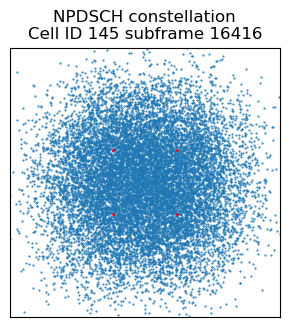
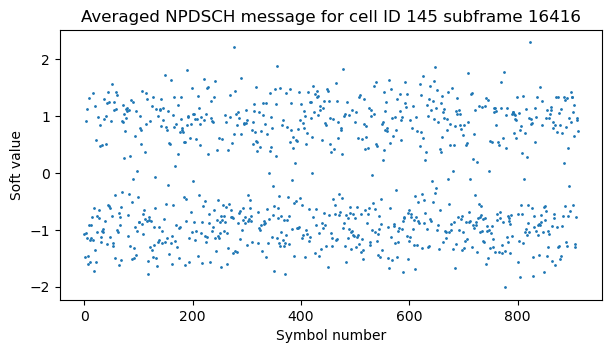
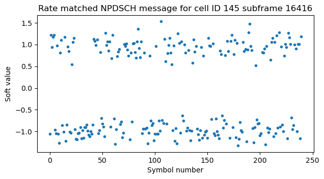
In contrast, the same transmission done by cell 123 has much worse SNR due to very high interference from the other cells. Nevertheless, the Viterbi decoder is able to decode the transport block correctly. In fact, we can decode all the NPDSCH transmissions for which we successfully decoded the NPDCCH transmission.
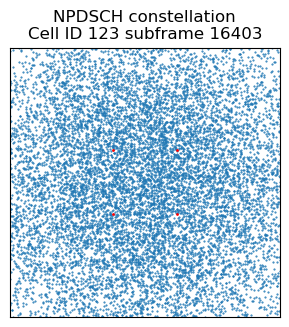
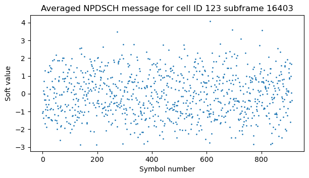
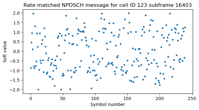
The following figure shows the first paging message in Wireshark. All the cells transmit this message almost simultaneously, since they are in the same tracking area (the difference in transmission times is just caused by different subframes being occupied by the SI messages). The paging message contains a list of paging records that indicate the S-TMSI of the UE being paged. The list can contain multiple entries if there are multiple UEs that need to be paged at the same time, but in this recording all the messages contain just one entry.
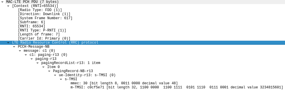
There are only 26 paging messages transmitted over the 340 seconds that the recording lasts. Together with the lack of other user traffic in these cells except for the one caused by my V16 beacon, this indicates that the NB-IoT network is seldomly used in this area.
This list shows the S-TMSIs in each paging message decoded in the recording. Only the messages transmitted by cell ID 145 are shown in the list. There are only 12 distinct S-TMSIs, as some of the UEs are paged multiple times.
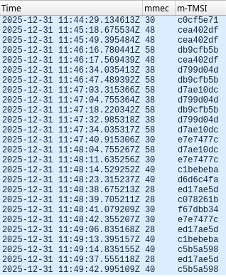
Paging scheduling
Paging is used by the network to reach a UE that has entered the I-DRX (idle mode discontinuous receive) state. In this state, the UE is not connected to the RRC and it only wakes up periodically to monitor paging occasions in the Type1 common search space where a paging message addressed to it might be transmitted. This allows the UE to save power by switching off the receiver between these paging occasions.
The parameters that control the Type1 common search space scheduling are given in the SIB2-NB and they were shown above. They are:
defaultPagingCycle-r13. This gives the value \(T\), which indicates the length of the DRX cycle in radio frames. Here \(T\) is 256 frames, or 2.56 seconds.nB-r13. This gives a parameter called \(nB\) that defines the number of paging occasions (POs) within the DRX cycle. The value of \(nB\) is defined in terms of \(T\), either as a multiple of \(T\) or as a fraction of \(T\). In our case it is \(T/16\).npdcch-NumRepetitionPaging-r13. This indicates the maximum number of NPDCCH repetitions used for the paging messages.
From the values of \(T\) and \(nB\) in the SIB2-NB, the following additional parameters are defined:
- \(N\), which indicates the number of paging frames (PFs) with the DRX cycle. It is defined as \(N = \min(T, nB)\). In our case, \(N = T/16 = 16\).
- \(N_s\), which indicates the number of paging occasions in each paging frame. It is defined as \(N_s = \max(1, nB/T)\). In our case \(N_s = 1\).
To determine when paging is transmitted for a given UE, we take its IMSI and reduce it modulo 4096 to obtain a quantity known as UE_ID. The paging frames for this UE are the ones whose SFN is congruent with \((T/N)\times(\mathrm{UE\_ID} \mod N)\) modulo \(T\). Therefore, in our case we see that the paging frames occur every 16 radio frames, and which one is selected with the DRX cycle of 256 radio frames depends on the IMSI modulo 16.
Next, we need to compute the \(i_s\) parameter as \(i_s = \lfloor\mathrm{UE\_ID}/N\rfloor \mod N_s\). This parameter define which of the paging occasions within the paging frame is used. In our case, \(N_s = 1\), since there is only one paging occasion per paging frame. So \(i_s\) is always zero regardless of the UE_ID. The value of \(i_s\) is used together with the following lookup table from TS 36.304 to obtain the starting subframe for the Type1 common search space NPDCCH paging occasions.
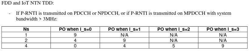
Here we see that the paging occasion always starts in subframe 9. However, since the paging frames are all even (they are multiples of 16), subframe 9 is occupied by the NSSS. Therefore, the beginning of the NPDCCH transmission shifts over to the next available subframe, which is subframe 1 in the next radio frame, since subframe 0 is occupied by the NPBCH. In some cases, the NPDCCH transmission needs to be delayed even more to avoid SI messages.
Looking at the starts of the paging NPDCCH that we have found manually in the plot of power per subframe, we see that all the SFNs in which paging happens are congruent with 1 modulo 16. This is what we expected. Additionally, if we divide the SFN minus one by 16 and reduce modulo 16, we should get the IMSI modulo 16. We don’t know the IMSIs of these UEs, but we know that multiple paging messages addressed to the same UE (which we can identify because they carry the same S-TMSI) should have the same IMSI. We indeed see that this happens.
V16 beacon downlink
Recall that in the post where I decoded the uplink recording, we saw the following. Approximately 80 seconds after power on, the V16 beacon performs its first RRC connection. In this connection it authenticates and attaches to the network. Once this is done, the network releases the V16 beacon RRC connection after 20 seconds of inactivity, which involves a brief exchange of messages. About 100 seconds after the first RRC connection, there is a second RRC connection. In this second connection, the V16 beacon uses a control plane service request to send its beacon data to the network. Then there is an RRC release after 20 seconds of inactivity. Finally, 100 seconds after the second RRC connection there is a third RRC connection that is essentially identical to the second one.
To decode the downlink transmissions sent by cell ID 261 to the V16 beacon, we need to use blind decoding to find the NPDCCH transmissions, because it is very difficult to detect these transmissions by looking at waterfall or power plots, due to the interference from the other cells.
The following figure shows the waterfall for the uplink and downlink channels, aligned in time, during the beginning of the first RRC connection of the V16 beacon. The first uplink transmission is the NPRACH. The second is the RRC connection request message sent in the NPUSCH. Between these two transmissions we know that there must be an NPDSCH transmission carrying the RAR (random access response). However, it is impossible to see it in the waterfall, specially because the other cells are also transmitting SI messages. It makes sense that this initial connection happens during an SI window. After powering on, the beacon needs to decode the SIB2-NB before attaching to the cell. It doesn’t need to wait for all the repetitions of the SI message to decode successfully, so it just begins the random access somewhere within in the SI window.

Another thing that we can observe in this waterfall is that the strong uplink transmissions cause some saturation in the receiver, which can be seen as interference in the downlink channel.
It is easier to work with the subsequent RRC connections. They happen roughly every 100 seconds, and they are not aligned with SI transmissions. For instance, in the second RRC connection all the other cells are not sending anything besides the SIB1-NB, NPBCH, NPSS and NSSS. We can barely see the NPDCCH and NPDSCH transmissions of cell 261 used to send the random access response.

In the first RRC connection there are many transmissions that cannot be decoded, due to interference from the SI messages of other cells. Therefore, I will begin by explaining how to decode the transmissions corresponding to the second connection.
Second RRC connection: RAR
The first transmission that we attempt to decode is the RAR. This is addressed to a RA-RNTI that is computed as \(1 + \lfloor \mathrm{SFN} / 4 \rfloor\), where \(\mathrm{SFN}\) is the SFN corresponding to the beginning of the NPRACH transmission. We can find the SFN just by looking at the uplink waterfall, since we know the correspondence between the recording time and the SFNs. The SFN is 627, so the RA-RNTI is 157.
Since the NPDCCH configuration for the RAR depends on the CE level, we also need to know what CE level is being used by the UE. The best way to find this is to look at the length of the NPRACH. The NPRACH configuration for cell ID 261 is shown here for convenience. In the waterfall we see that the NPRACH is composed of 8 sequences of 4 tones. Therefore, the UE is using CE1, which is the configuration that has numRepetitionsPerPreambleAttempt-r13 set to 8.
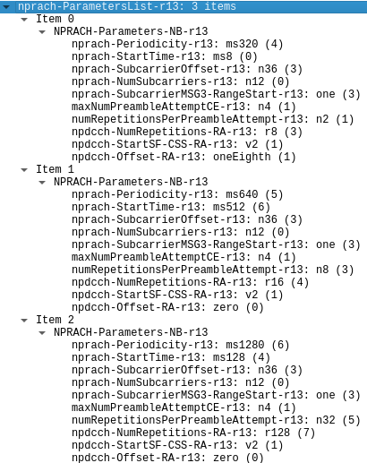
For CE1, the npdcch-NumRepetitions-RA-r13 field is 16. This field gives the maximum number of NPDCCH repetitions for the Type2 common search space, used for the RAR, Msg3 retransmission (recall that Msg3 is the RRC connection request sent by the UE) and Msg4 (which is the contention resolution MAC control element, typically sent together with the RRC connection setup message). As in the case of the Type1 common search space, there is a table in TS 36.213 that lists the candidates that need to be used for blind decoding in the Type2 common search space depending on the value of \(R_{\mathrm{max}}\), which here is 16. Therefore, we see that the actual number of repetitions of the NPDCCH can be \(R = 2, 4, 8, 16\), depending on the DCI subframe repetition number carried in the DCI.
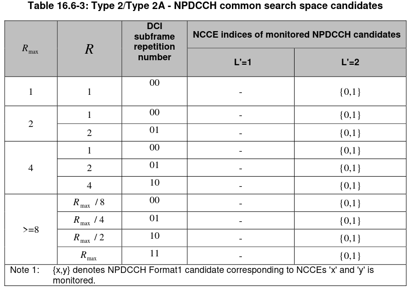
The NPDCCH scheduling on the Type2 common search space and the UE-specific space works differently from the Type1 common search space scheduling. Besides the \(R_{\max}\) parameter, which indicates both the maximum number of repetitions of a DCI as well as the number of subframes occupied by the search space, the scheduling depends on two other parameters, \(\alpha\), which indicates the time offset of the search space, and \(G\), which defines the periodicity of the search space as \(T = R_{\mathrm{max}}G\).
In the case of the Type2 common search space, the parameter \(G\) is given by the npdcch-StartSF-CSS-RA-r13 field in the SIB2. In our case this has the value 2. This means that the period of the search space is \(T = R_{\mathrm{max}}G = 16 \cdot 2 = 32\) subframes. The search space beings on subframes whose subframe number (the SFN plus the number of the subframe within the radio frame) is congruent with \(\lfloor \alpha T\rfloor\) modulo \(T\). For the Type2 common search space, \(\alpha\) is given by npdcch-Offset-RA-r13, and it is zero in our case.
Therefore, for CE1 the Type2 common search space for this cell begins on every subframe number congruent with zero modulo 32 and has a length of 16 subframes. As usual, the subframes used by the search space skip over subframes used for the NPBCH, NPSS, NSSS and system information. An additional scheduling restriction is that a DCI with \(R\) repetitions can only start at subframe offsets within the search space that are multiples of \(R\). For instance, a DCI that has \(R = R_{\mathrm{max}} / 2\) can either occupy the first half of the search space or the second half, while a DCI that has \(R = R_{\mathrm{max}} / 4\) must occupy one of the four quarters of the search space.
The tutorial paper about the NB-IoT physical layer shows the following example for a Type2 common search space that has \(R_{\mathrm{max}} = 32\), \(G = 2\), and \(\alpha = 1/4\), so the search space begins at every subframe number congruent with 16 modulo 64, and lasts for 32 subframes. The possible starting subframes for a DCI that uses \(R = 8\) are shown. Note that this example assumes that system information (including the SIB1-NB) is not transmitted in the radio frames shown.
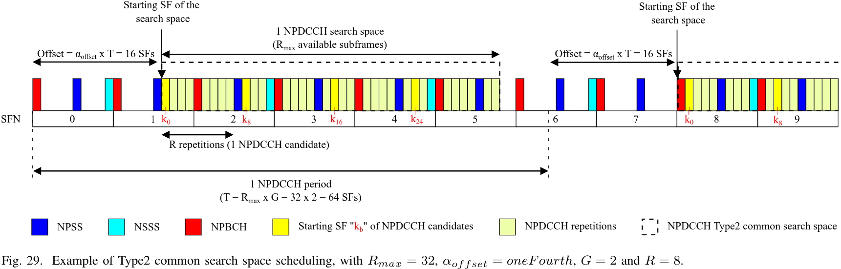
With some trial and error or a proper blind decoding search, which I have implemented for the sake of finding the rest of the NPDCCH transmissions, we find that the NPDCCH for the RAR of this RRC connection is transmitted in the search space in SFN 630 subframe 4. According to the SIB2-NB, the NPRACH window for CE1 has a periodicity of 640 ms and an offset of 512 ms. This means that the NPRACH transmission actually begins in SFN 627 subframe 2. The transmission lasts 44.8 ms, so it ends in SFN 631 subframe 6. It turns out that the NPDCCH transmission has 4 repetitions (which is confirmed by the subframe repetition number in the DCI) and begins in subframe 12 of the search space, which is actually SFN 632 subframe 2, due the occupied subframes that are skipped over. Therefore, we see that the RAR NPDCCH is sent at the first chance after the NPRACH window end. The transport block size for this DCI is 23 bits, which is the size of DCI formats N0 and N1 used in the Type2 common search space.
The following plots show the constellation of this NPDCCH transmission, the soft symbols after averaging the 4 repetitions, and the convolutional codeword after undoing rate matching. The codeword almost looks like noise, but nevertheless the Viterbi decoder can successfully obtain the DCI. I find quite amazing how the NB-IoT channel coding allows decoding messages even in these very poor conditions.
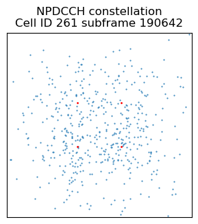
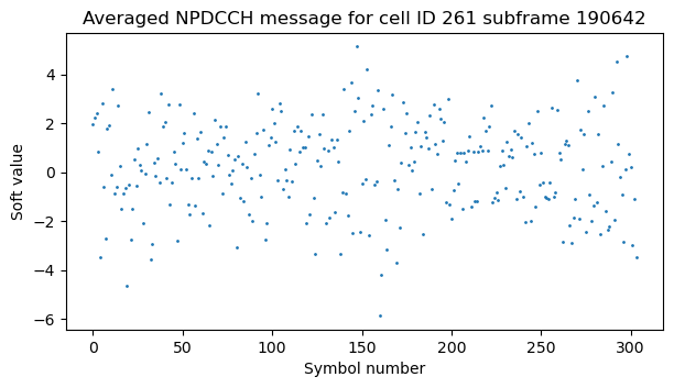
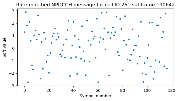
The fields of DCI formats N0 and N1 are defined in Sections 6.4.3.1 and 6.4.3.2 of TS 36.212. The first bit of both formats is a flag that has the value 0 for format N0 and the value 1 for format N1. This is used to distinguish the formats, since they are both transmitted in the same NPDCCH search space and have the same transport block size. DCI format N1 is used to send NPDSCH scheduling. The remaining fields of this format are the following:
- Scheduling delay \(I_{\mathrm{Delay}}\) (3 bits). This determines the delay between the NPDCCH transmission and the corresponding NPDSCH transmission. The starting subframe for the NPDSCH is \(k_0 + n + 5\), where \(n\) is the last subframe of the NPDCCH, and \(k_0\) is defined from the index \(I_{\mathrm{Delay}}\) using the table below. In this recording, all the DCI format N1 messages have \(I_{\mathrm{Delay}} = 0\), so the gap between the NPDCCH and the NPDSCH is the minimum of 4 subframes.
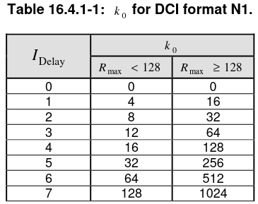
- Resource assignment \(I_{\mathrm{SF}}\) (3 bits). This works in the same way as for the DCI format N2. It defines the number of subframes \(N_{\mathrm{SF}}\) used by the NPDSCH according to the table shown earlier.
- Modulation and coding scheme \(I_{\mathrm{MCS}}\) (4 bits). When QPSK is used, this sets \(I_{\mathrm{TBS}} = I_{\mathrm{MCS}}\) and defines the transport block size in terms of \(I_{\mathrm{SF}}\) in the same way as for the DCI format N2. In the UE-specific search space, when a UE has 16QAM enabled, the value \(I_{\mathrm{MCS}} = 15\) is used as the 16QAM indicator. When 16QAM is used, \(I_{\mathrm{TBS}} = I_{\mathrm{MCS}}’ + 14\), where \(I_{\mathrm{MCS}}’\) is the value of the repetition number field, which is repurposed as 16QAM MCS.
- Repetition number \(I_{\mathrm{Rep}}\) (4 bits). This indicates the number of repetitions \(N_{\mathrm{Rep}}\) of the NPDSCH using a table as for DCI format N2. Note that this field is repurposed as 16QAM MCS when 16QAM is used.
- New data indicator (1 bit). This is used by the HARQ process to determine if the NPDSCH corresponds to new data or if it is a retransmission. The new data indicator is toggled whenever a new transport block is transmitted.
- HARQ-ACK resource (4 bits). This defines the resource allocation for the NPUSCH format 2 transmission that sends the ACK/NACK for the NPDSCH. The value of this field indicates the subcarrier used for the NPUSCH and the time delay with respect to the end of the NPDSCH according to this table. Note however that the RAR is not replied with an ACK/NACK. It is replied with the Msg3. So this field is unused for the RAR DCI.
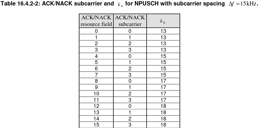
- DCI subframe repetition number (2 bits). This field indicates the actual number of repetitions \(R\) used by this DCI according to the table above that shows the possible search space candidates.
In the case of the DCI format N1 sent for the RAR, the contents of the fields are as follows.
DCI format N1
-------------
- I_delay = 0
- N_SF = 3 (I_SF = 2)
- I_TBS = 1
- N_rep = 8
- new data indicator = 0
- HARQ-ACK resource = 0
- DCI subframe repetition number = [0, 1]
Using this information, we can decode the corresponding NPDSCH transmission. The constellation of this transmission looks more decent than other transmissions from cell ID 261.
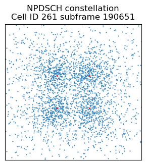
The NPDSCH transmission carries a MAC PDU containing the RAR. This is dissected in Wireshark here.
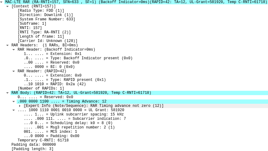
The main thing of interest in the RAR is the temporary C-RNTI assigned to the UE. We need this to perform blind decoding of the following NPDCCH transmissions. However, I had already found this C-RNTI in the post about the uplink. Additionally, the RAR contains an uplink grant for the Msg3 transmission. This indicates that a single-carrier NPUSCH format 1 transmission using subcarrier 7 should be used. The MCS index gives the corresponding modulation, number of resource units, and transport block size used for the Msg3 NPUSCH. For the index 1 we have \(\pi/4\)-QPSK with 3 resource units and 88 bits of transport block size. We see that this matches what we found in cell [62] of the uplink decoding notebook.
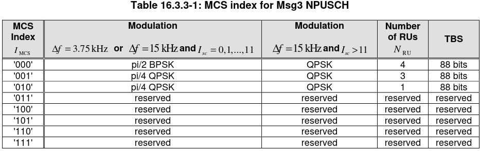
Second RRC connection: RRC connection setup
After the transmission of the RAR, the UE sends the RRC connection request Msg3 that we had decoded in the post about the uplink. We continue doing blind decoding in the Type2 common search space with the C-RNTI to find the next downlink transmissions sent to the V16 beacon.
The next NPDCCH transmission carries a DCI format N1 with the following information.
DCI format N1
-------------
- I_delay = 0
- N_SF = 10 (I_SF = 7)
- I_TBS = 1
- N_rep = 4
- new data indicator = 1
- HARQ-ACK resource = 0
- DCI subframe repetition number = [0, 1]
The MAC PDU in the corresponding NPDSCH transmission carries a contention resolution identity and an RRC connection setup message. The contention resolution identity matches the ASN encoded S-TMSI that the UE sent as UE identity in the RRC connection request message (we decoded this in the uplink post).
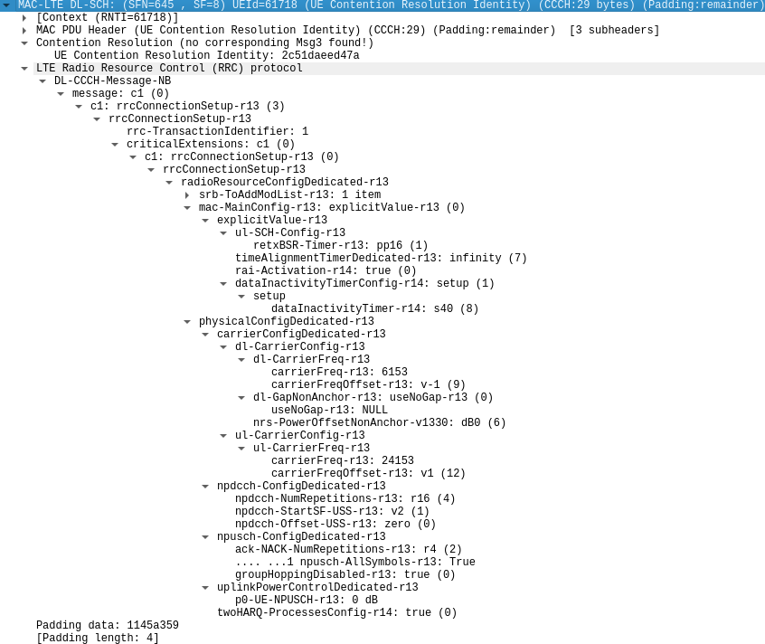
The RRC connection setup message sets the uplink carrier to the same values that were included in the SIB2-NB. It also sets the downlink carrier. The downlink EARFCN is 6153, which corresponds to 791.3 MHz in the B20 band, as I mentioned above. Additionally, there is a frequency offset of -1, which corresponds to a frequency shift of -2.5 kHz, matching the value seen in the MIB-NB.
The configuration of the UE-specific search space for the NPDCCH is given in the npdcch-ConfigDedicated-r13 section. The parameters are \(R_{\mathrm{max}} = 16\), \(G = 2\), and \(\alpha = 0\), the same as for the CE1 Type2 common search space.
The NPUSCH format 2 is configured to 4 repetitions. The npusch-AllSymbols-r13 field is used to indicate whether NPUSCH transmission should avoid the symbols used by the LTE SRS (sounding reference signal). This only can happen for in-band cells. Group hopping is disabled in the NPUSCH DMRS, as we already knew from decoding the uplink.
Finally, two HARQ processes are enabled for this UE. If we look back at the PCAP file of the uplink, we see that in the UE capability information message sent by the UE in the first RRC connection to the network, it stated that it supports two HARQ processes, so now the network is enabling this feature. We will need to have this in mind, because it means that the transport block size of the DCI format N0 and N1 messages sent to the UE in the UE-specific search space will be 24 bits rather than 23, as there will be an extra bit to indicate the HARQ process.
The srb-ToAddModList-r13 section was collapsed in the above figure for the sake of space. It is shown here for completeness. It is just setting SRB 3 as an AM bearer for DCCH traffic.
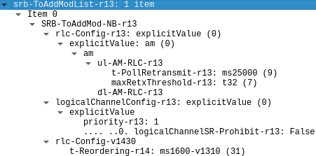
The UE sends the NPUSCH format 2 ACK to the NPDSCH transmission of the RRC connection setup message in cell [63] of the uplink Jupyter notebook.
After the RRC connection setup message, I would expect to see three DCI format N0 transmissions in the UE-specific search space, because in the uplink post we saw that there were three NPUSCH transmissions: an RRC connection setup complete message carrying the control plane service request encrypted message, and a retransmission of the beginning of this AM PDU as two AM segments (However now we know that the t-PollRetransmit-r13 field was configured to 25 seconds, so the retransmit timer had certainly not expired. I am not sure why the UE decided to retransmit this SDU). These NPUSCH transmissions need to have corresponding uplink grants in DCI format N0 messages, but I cannot find them using blind decoding. I assume that their SNR is too low (probably there is too much interference from other cells), since the same code works fine to decode the similar DCI format N0 transmissions in the third RRC connection done by the V16 beacon.
Second RRC connection: response to control plane service request
The next NPDCCH transmission that I can find using blind decoding is a DCI format N1 sent in the UE-specific search space. It contains the following data.
DCI format N1
-------------
- I_delay = 0
- N_SF = 6 (I_SF = 5)
- I_TBS = 1
- N_rep = 4
- new data indicator = 1
- HARQ-ACK resource = 0
- DCI subframe repetition number = [0, 1]
- HARQ process number = 1
Note that the HARQ process number field is present in the DCI. The second downlink HARQ process is used for this transmission. The new data indicator is set to 1. I assume that this is because even though this is the first time that the downlink HARQ process number 1 is used, the new data indicator was set to 0 in the previous transmission (which was done when there was a single HARQ process active).
The NPDSCH transmission corresponding to this DCI format N1 carries the following MAC PDU. There is an AM ACK that acknowledges the RRC connection setup complete sent by the UE. There is also another AM PDU that contains a dlInformationTransfer-r13 message that sends a NAS PDU to the UE. The NAS PDU contains a ciphered message. This is sent by the network as a response to the message that the V16 beacon sent as a control plane service request. The ciphered message is very short, so I guess it is just an acknowledgement that confirms that the UE message was correctly delivered by the network.
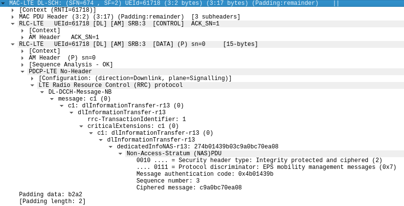
The next NPDCCH transmission is a DCI format N0. Besides the flag that distinguishes formats N0 and N1, the DCI format N0 has the following fields:
- Subcarrier indication \(I_{\mathrm{sc}}\) (6 bits). This defines the subcarriers to be used for the NPUSCH transmission according to the following table.
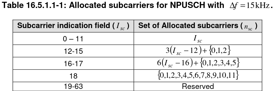
- Resource assignment \(I_{\mathrm{RU}}\) (3 bits). This defines the number of resource units \(N_{\mathrm{RU}}\) used for the NPUSCH transmission according to this table.
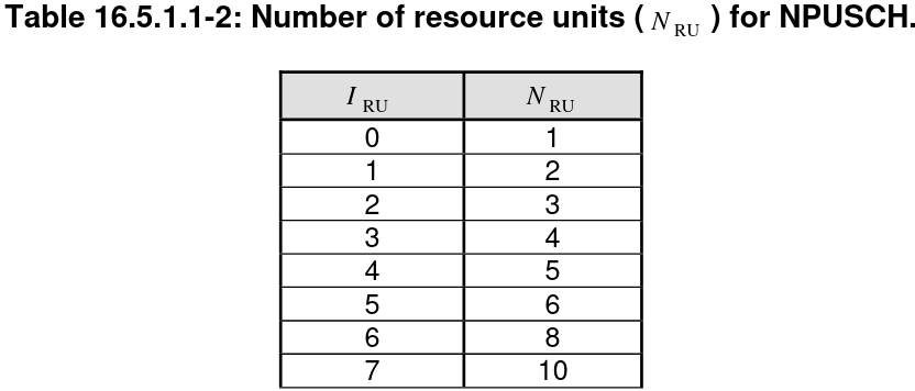
- Scheduling delay \(I_{\mathrm{Delay}}\) (2 bits). This defines the delay \(k_0\) between the NPDCCH transmission and the corresponding NPUSCH allocation.
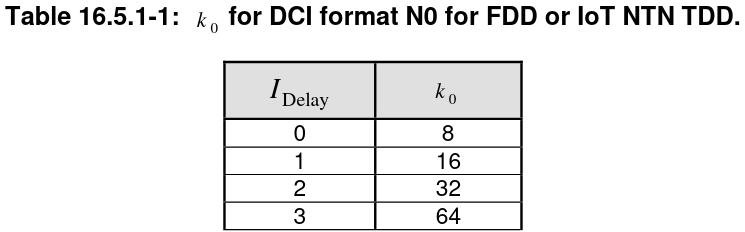
- MCS \(I_{\mathrm{MCS}}\) (4 bits). This defines the modulation order and the transport block size. For a single-carrier NPUSCH transmission, the TBS index \(I_{\mathrm{TBS}}\) and the modulation order is defined by the following table. For multi-carrier NPUSCH using QPSK, \(I_{\mathrm{TBS}} = I_{\mathrm{MCS}}\). For multi-carrier NPUSCH using 16QAM, \(I_{\mathrm{MCS}}\) is set to 15 as a 16QAM indicator, and \(I_{\mathrm{TBS}} = I_{\mathrm{MCS}}’ + 14\), where \( I_{\mathrm{MCS}}’\) is the contents of the repetition number field in the DCI, which is repurposed as a 16QAM MCS. The transport block size is defined in terms of \(I_{\mathrm{TBS}}\) and \(I_{\mathrm{RU}}\) through the table below.
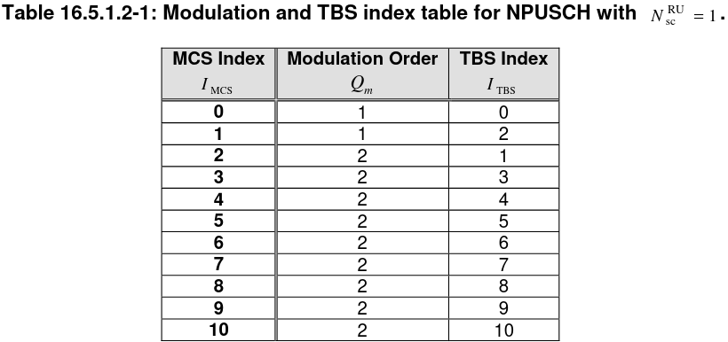
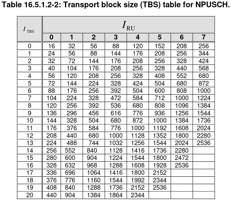
- Redundancy version (1 bit). This indicates the HARQ redundancy version that is requested for the first repetition of the NPUSCH transmissions. Only redundancy versions 0 and 2 are used, so the value 1 of this field corresponds to redundancy version 2. After the first repetition, the redundancy version of subsequent repetitions alternates between 0 and 2.
- Repetition number \(I_{\mathrm{Rep}}\) (3 bits). Indicates the number of repetitions \(N_{\mathrm{Rep}}\) of the NPUSCH transmission according to the following table. If the modulation is 16QAM, only one repetition is used, and the value of this field is used as the 16QAM MCS as described above.
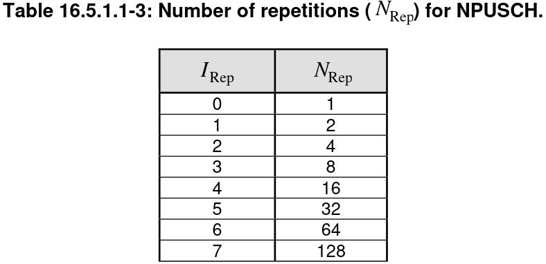
- New data indicator (1 bit). This bit indicates whether a new transport block or a retransmissions is being requested by the HARQ process. The bit toggles each time that a new transport block is requested.
- DCI subframe repetition number (2 bits). It indicates the actual number of NPDCCH repetitions \(R\) used by this DCI, according to the tables shown above for the Type2 common search space and the UE-specific search space.
- HARQ process number (1 bit). This bit is only present when two HARQ processes are enabled as described above. The bit indicates which HARQ process is used for the NPUSCH transmission.
This DCI format N0 transmission contains the following fields.
DCI format N0
-------------
- Subcarriers = [6, 7, 8, 9, 10, 11]
- N_RU = 6 (I_RU = 5)
- scheduling delay k_0 = 8
- I_MCS = 13
- redundancy version = 0
- N_rep = 1
- new data indicator = 0
- DCI subframe repetition number = [0, 1]
- HARQ process number = 0
The corresponding NPUSCH transmission is the one that I decoded in cell [70] of the uplink Jupyter notebook. It only contains an AM ACK that acknowledges the reception of the dlInformationTransfer message sent by the NAS.
Second RRC connection: padding-only uplink transmissions
After this DCI format N0 transmission, there are the following two other DCI format N0 transmissions. They contain identical values except for the HARQ process number. The eNB is requesting new data from the UE by doing round robin over the two HARQ processes.
DCI format N0
-------------
- Subcarriers = [0, 1, 2, 3, 4, 5, 6, 7, 8, 9, 10, 11]
- N_RU = 1 (I_RU = 0)
- scheduling delay k_0 = 8
- I_MCS = 13
- redundancy version = 0
- N_rep = 1
- new data indicator = 1
- DCI subframe repetition number = [0, 1]
- HARQ process number = 1
DCI format N0
-------------
- Subcarriers = [0, 1, 2, 3, 4, 5, 6, 7, 8, 9, 10, 11]
- N_RU = 1 (I_RU = 0)
- scheduling delay k_0 = 8
- I_MCS = 13
- redundancy version = 0
- N_rep = 1
- new data indicator = 1
- DCI subframe repetition number = [0, 1]
- HARQ process number = 0
The NPUSCH transmissions are in cells [71] and [72] in the uplink notebook. They only contain padding, since the V16 beacon does not have any more data to send.
Second RRC connection: RRC connection release
After these NPUSCH transmissions, there are no more transmissions from the V16 beacon until 20 seconds later, when the RRC connection release occurs. In the uplink we only saw an NPUSCH format 2 transmission that acknowledges something that the cell sent on the downlink, and an NPUSCH format 1 transmission that sends an AM ACK.
We do blind decoding in the UE-specific search space slightly before these uplink transmissions and first we find the following DCI format N1.
DCI format N1
-------------
- I_delay = 0
- N_SF = 3 (I_SF = 2)
- I_TBS = 1
- N_rep = 4
- new data indicator = 0
- HARQ-ACK resource = 0
- DCI subframe repetition number = [0, 1]
- HARQ process number = 0
The corresponding NPDSCH transmission carries the following RRC connection release message. The possible release causes are loadBalancingTAUrequired, rrc-Suspend and other, so it makes sense that the cause is other for this release caused by UE inactivity.
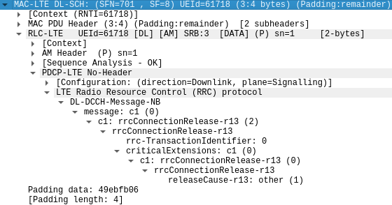
The UE sends the NPUSCH format 2 ACK to this message in cell [75] of the uplink Jupyter notebook. Then there is a DCI format N0 that schedules uplink resources so that the UE can reply to this message on the RLC layer.
DCI format N0
-------------
- Subcarriers = [0, 1, 2, 3, 4, 5, 6, 7, 8, 9, 10, 11]
- N_RU = 1 (I_RU = 0)
- scheduling delay k_0 = 8
- I_MCS = 13
- redundancy version = 0
- N_rep = 1
- new data indicator = 0
- DCI subframe repetition number = [0, 1]
- HARQ process number = 0
The corresponding NPUSCH transmission is cell [76] in the uplink notebook.
Third RRC connection
The third RRC connection done by the V16 beacon is essentially identical to the second one, except that there are no DCI format N0 messages that cannot be decoded from the recording because of too much interference. I will briefly summarize the conversation on this connection. The UE also uses CE1 to initiate NPRACH. The eNB sends a DCI format N1 in the Type2 common search space using the corresponding RA-RNTI. The NPDSCH transmission carries the RAR, which contains a temporary C-RNTI and an uplink grant to send the Msg3. The UE sends the RRC connection request message in an NPUSCH format 1 transmission using this uplink grant. The eNB transmits a DCI format N1 in the common search space addressed to the C-RNTI. The NPDSCH transmission contains the RRC connection setup message. The UE acknowledges this transport block with an NPUSCH format 2. The eNB sends a DCI format N0 to the UE-specific search space. The UE transmits NPUSCH format 1, sending the RRC connection setup complete message that contains the control plane service request.
The eNB now sends 3 more DCI format N0 for smaller transport block sizes. The UE uses these uplink grants to transmit the RRC connection setup complete message again segmented into 3 AM PDUs. The eNB then sends a DCI format N1. The NPDSCH transmission carries an AM ACK for the RRC connection setup complete and a dlInformationTransfer ciphered message that contains the network reply to the control plane service request. The UE sends the corresponding NPUSCH format 2 ACK. Then a DCI format N0 is sent. The UE uses the uplink grant to transmit an AM ACK confirming the reception of the dlInformationTransfer message.
The eNB then sends another DCI format N1. Its NPDSCH carries an AM ACK. This repeated AM ACK has been sent because the UE has actually sent the RRC connection setup complete message twice, so the network is acknowledging the successful reception of the retransmission. The UE sends NPUSCH format 2 confirming the reception of this NPDSCH transport block. Then there are two DCI format N0, but the UE does not have more data to send, so it sends only padding in the corresponding NPUSCH format 1 transmissions. Finally, the RRC connection release happens 20 seconds afterwards in the same way as before.
First RRC connection: initial messages
Let us now go back to the first RRC connection. This is more complex, because the UE needs to authenticate and attach to the network, so there are additional messages exchanged. Moreover, there is much more interference from the other cells, as this connection happens during an SI window. Additionally, the UE uses CE0 instead of CE1, so the eNB generally uses fewer repetitions, which makes decoding more difficult. Therefore, I have been unable to decode most NPDSCH transmissions, so we will need to piece together the conversation mostly from the context and from the uplink carrier.
First, the UE sends NPRACH using the CE0 level configuration. I have been unable to locate the corresponding NPDCCH transmission for the RAR using blind decoding. However, from having decoded the uplink, I know that the C-RNTI is 60426, so I can use that to attempt blind decoding of the subsequent NPDCCH transmission in the Type2 common search space. For CE0 level, this search space is configured with \(R_{\mathrm{max}} = 8\), \(G = 2\), \(\alpha = 1/8\). The DCI transmissions that I have found all use \(R = 4\).
First RRC connection: attach request
The first NPDCCH transmission that I have managed to decode is the following one. The corresponding NPUSCH transmission is in cell [34] in the uplink Jupyter notebook. It carries an RRC connection setup complete that includes attach request and PDN connectivity request messages.
DCI format N0
-------------
- Subcarriers = [0, 1, 2]
- N_RU = 4 (I_RU = 3)
- scheduling delay k_0 = 8
- I_MCS = 11
- redundancy version = 0
- N_rep = 1
- new data indicator = 0
- DCI subframe repetition number = [1, 0]
Before the RRC connection setup complete, the UE has transmitted an NPUSCH format 1 carrying the RRC connection request message. This is the Msg3 sent as reply to the RAR that we have missed. The UE has also sent an NPUSCH format 2 acknowledging a downlink transport block. This transport block must have been the RRC connection setup message from the eNB. We have even missed its NPDCCH format N1 transmission.
After the RRC connection setup complete, there is a DCI format N1, but the NPDSCH cannot be decoded. The UE replies with an NPUSCH format 2 ACK in cell [35] of the notebook.
DCI format N1
-------------
- I_delay = 0
- N_SF = 1 (I_SF = 0)
- I_TBS = 4
- N_rep = 2
- new data indicator = 0
- HARQ-ACK resource = 0
- DCI subframe repetition number = [1, 0]
Then there is a similar DCI format N1, and again the NPDSCH cannot be decoded. The UE sends the NPUSCH ACK in cell [36].
DCI format N1
-------------
- I_delay = 0
- N_SF = 6 (I_SF = 5)
- I_TBS = 4
- N_rep = 2
- new data indicator = 1
- HARQ-ACK resource = 0
- DCI subframe repetition number = [1, 0]
First RRC connection: UE capability information
Next, there is the following DCI format N0. The corresponding NPUSCH format 1 is in cell [37] in the uplink notebook. This NPUSCH contains an AM ACK with sequence number 1 in SRB 3. Therefore, the two NPDSCH transmissions sent earlier by the eNB are most likely an AM ACK that acknowledges the RRC connection setup complete message, and an AM PDU with sequence number 0, which is what the AM ACK is acknowledging now. The NPUSCH PDU also contains the first fragment of a UE capability information message. Therefore, we infer that the AM PDU sent by the eNB was a UE capability enquiry message.
DCI format N0
-------------
- Subcarriers = [0, 1, 2]
- N_RU = 1 (I_RU = 0)
- scheduling delay k_0 = 8
- I_MCS = 11
- redundancy version = 0
- N_rep = 1
- new data indicator = 1
- DCI subframe repetition number = [1, 0]
The eNB then sends another DCI format N0. The NPUSCH is in cell [38] of the uplink notebook and contains the second AM fragment of the UE capability information message.
DCI format N0
-------------
- Subcarriers = [0, 1, 2, 3, 4, 5]
- N_RU = 1 (I_RU = 0)
- scheduling delay k_0 = 8
- I_MCS = 11
- redundancy version = 0
- N_rep = 1
- new data indicator = 0
- DCI subframe repetition number = [1, 0]
Then there is another DCI format N0. The NPUSCH is in cell [39], and it contains a retransmission of the second AM fragment of the UE capability information message.
DCI format N0
-------------
- Subcarriers = [0, 1, 2, 3, 4, 5, 6, 7, 8, 9, 10, 11]
- N_RU = 2 (I_RU = 1)
- scheduling delay k_0 = 8
- I_MCS = 11
- redundancy version = 0
- N_rep = 1
- new data indicator = 1
- DCI subframe repetition number = [1, 0]
Next we have the following DCI format N1. As usual, the NPDSCH cannot be decoded, but we have the NPUSCH format 2 ACK from the UE in cell [40] of the uplink notebook.
DCI format N1
-------------
- I_delay = 0
- N_SF = 1 (I_SF = 0)
- I_TBS = 4
- N_rep = 2
- new data indicator = 0
- HARQ-ACK resource = 0
- DCI subframe repetition number = [1, 0]
Then we have another DCI format N0. The UE retransmits again the second AM fragment of the UE capability information in cell [41] of the uplink notebook.
DCI format N0
-------------
- Subcarriers = [0, 1, 2, 3, 4, 5, 6, 7, 8, 9, 10, 11]
- N_RU = 1 (I_RU = 0)
- scheduling delay k_0 = 8
- I_MCS = 12
- redundancy version = 0
- N_rep = 1
- new data indicator = 0
- DCI subframe repetition number = [1, 0]
First RRC connection: authentication response
The next NPDCCH transmission is the following DCI format N0. The NPUSCH transmission is in cell [42] of the uplink notebook. It carries an authentication response NAS PDU. We infer that the network must have sent an authentication request NAS PDU at some point. But where is it? I cannot have missed a DCI format N1, because I would have still seen the NPUSCH format 2 transmission that acknowledges the NPDSCH transport block. Therefore, the conclusion is that this authentication request was sent with the previous DCI format N1. However, it is strange that the UE used the previous uplink grant to still send the last AM fragment of the UE capability information.
DCI format N0
-------------
- Subcarriers = [0, 1, 2, 3, 4, 5, 6, 7, 8, 9, 10, 11]
- N_RU = 1 (I_RU = 0)
- scheduling delay k_0 = 8
- I_MCS = 12
- redundancy version = 0
- N_rep = 1
- new data indicator = 1
- DCI subframe repetition number = [1, 0]
Next we have a DCI format N1. Its NPDSCH transmission can be decoded successfully this time. It only contains an AM ACK with a sequence number of 3. The second fragment of the UE capability information had sequence number 2, so the network is acknowledging receipt of the UE capability information message. The NPUSCH format 2 ACK is in cell [43] of the uplink notebook.
DCI format N1
-------------
- I_delay = 0
- N_SF = 1 (I_SF = 0)
- I_TBS = 4
- N_rep = 2
- new data indicator = 1
- HARQ-ACK resource = 0
- DCI subframe repetition number = [1, 0]
Then we have another DCI format N1, but its NPDSCH cannot be decoded. We have the NPUSCH format 2 ACK in cell [44].
DCI format N1
-------------
- I_delay = 0
- N_SF = 5 (I_SF = 4)
- I_TBS = 4
- N_rep = 2
- new data indicator = 0
- HARQ-ACK resource = 0
- DCI subframe repetition number = [1, 0]
First RRC connection: security mode complete
The next NPDCCH transmission is a DCI format N0. The NPUSCH transmission is in cell [45] of the uplink notebook. It carries two AM PDUs. The first is an AM ACK with sequence number 2. This makes sense, because we have inferred that the network must have sent a UE capability enquiry and an authentication request, so these would have AM sequence numbers 0 and 1 respectively (recall that the RRC connection setup message is sent in the CCCH instead of the DCCH, and it does not use AM, since the DCCH SRB is established by that message). The second AM PDU is the first fragment of a NAS ciphered message. The ciphered message is probably a security mode complete message. This means that the network must have sent a security mode command message. This was probably what the previous NPDSCH transmission carried.
DCI format N0
-------------
- Subcarriers = [0, 1, 2, 3, 4, 5]
- N_RU = 1 (I_RU = 0)
- scheduling delay k_0 = 8
- I_MCS = 12
- redundancy version = 0
- N_rep = 1
- new data indicator = 0
- DCI subframe repetition number = [1, 0]
Then we have another DCI format N0. The NPUSCH transmission is in cell [46], and it carries the second AM fragment of the NAS ciphered message.
DCI format N0
-------------
- Subcarriers = [0, 1, 2, 3, 4, 5, 6, 7, 8, 9, 10, 11]
- N_RU = 4 (I_RU = 3)
- scheduling delay k_0 = 16
- I_MCS = 12
- redundancy version = 0
- N_rep = 1
- new data indicator = 1
- DCI subframe repetition number = [1, 0]
Next, a DCI format N1 is sent. In this case, the NPDSCH can also be decoded successfully. It contains only an AM ACK with sequence number 6. Looking at what the UE has sent, the second fragment of the NAS ciphered message has sequence number 5, so the network is confirming reception of this ciphered message. The NPUSCH format 2 ACK is in cell [47] in the uplink notebook.
DCI format N1
-------------
- I_delay = 0
- N_SF = 1 (I_SF = 0)
- I_TBS = 4
- N_rep = 2
- new data indicator = 1
- HARQ-ACK resource = 0
- DCI subframe repetition number = [1, 0]
Then there are the following two DCI format N1 messages, but their NPDSCH transmission cannot be decoded. Their corresponding NPUSCH format 2 ACKs are in cells [48] and [49] of the uplink notebook.
DCI format N1
-------------
- I_delay = 0
- N_SF = 10 (I_SF = 7)
- I_TBS = 4
- N_rep = 2
- new data indicator = 0
- HARQ-ACK resource = 0
- DCI subframe repetition number = [1, 0]

DCI format N1
-------------
- I_delay = 0
- N_SF = 8 (I_SF = 6)
- I_TBS = 4
- N_rep = 2
- new data indicator = 1
- HARQ-ACK resource = 0
- DCI subframe repetition number = [1, 0]
First RRC connection: attach complete
We go onto a DCI format N0 transmission, which has the corresponding NPUSCH in cell [50] of the uplink notebook. This NPUSCH transmission contains two AM PDUs. The first one is an AM ACK with a sequence number of 4. Therefore, the two previous NPDSCH transmission probably carried two AM PDUs with sequence numbers 2 and 3. The second AM PDU is a NAS encrypted message. As I mentioned in the post about the uplink recording, this message is probably an attach complete NAS message. This means that the network must have previously sent an attach accept NAS ciphered message. This message would contain an activate default EPS bearer context request ESM message containing the PDN configuration. This message is rather lengthy, so it makes sense that it was fragmented into two AM PDUs, matching the two DCI format N1 messages that we have seen.
DCI format N0
-------------
- Subcarriers = [0, 1, 2, 3, 4, 5, 6, 7, 8, 9, 10, 11]
- N_RU = 1 (I_RU = 0)
- scheduling delay k_0 = 8
- I_MCS = 12
- redundancy version = 0
- N_rep = 1
- new data indicator = 0
- DCI subframe repetition number = [1, 0]
Then there are two more DCI format N1 transmissions. As usual, their NPDSCH transmissions fail to decode. The NPUSCH format 2 ACKs are in cells [51] and [52] of the uplink notebook.
DCI format N1
-------------
- I_delay = 0
- N_SF = 1 (I_SF = 0)
- I_TBS = 4
- N_rep = 2
- new data indicator = 0
- HARQ-ACK resource = 0
- DCI subframe repetition number = [1, 0]

DCI format N1
-------------
- I_delay = 0
- N_SF = 5 (I_SF = 4)
- I_TBS = 5
- N_rep = 2
- new data indicator = 1
- HARQ-ACK resource = 0
- DCI subframe repetition number = [0, 1]
There is an NPUSCH format 1 transmission in cell [53] of the uplink notebook, but I haven’t been able to find the corresponding DCI format N0 transmission using blind decoding. I guess that the problem is interference from the other cells. This NPUSCH transmission only carries an AM ACK with sequence number 5. This probably makes sense, because from the two previous NPDSCH transmissions, probably the first one was just an AM ACK for the attach accept message (its length was only one subframe, so the transport block was quite short), while the second one was probably an AM data PDU with sequence number 4.
First RRC connection: RRC connection release
After 20 seconds of inactivity, the RRC connection release happens. This is very similar to the RRC connection releases of the other two RRC connections. However, the transport block size for the DCIs is 23 bits instead of 24 because the eNB has not requested the second HARQ process to be enabled. That makes sense, because the two HARQ processes are enabled in the RRC connection setup, but the UE capability information is sent after the RRC connection setup, so after learning that the UE supports two HARQ processes, the eNB cannot enable this feature unless it decides to perform an RRC connection reconfiguration.
Another difference is that the NPDSCH transmission that carries the RRC connection release message cannot be decoded successfully.
Summary of conversations
The following figure shows all the frames decoded on the uplink and downlink for the second and third RRC connections. I’m not showing the first RRC connection because we missed most of the downlink packets.
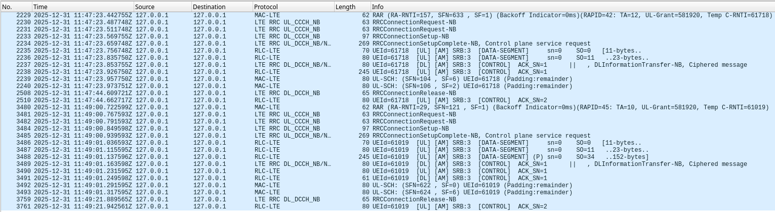
We can see that the process in these connections in which the V16 beacon just sends its data to the network is always the same:
- The UE sends NPRACH
- The eNB replies with a RAR
- The UE sends an RRC connection request message
- The eNB replies with an RRC connection setup message
- The UE replies with an RRC connection setup complete message that encapsulates a control plane service request message
- The UE retransmits the RRC connection setup message complete because it is still granted uplink resources and the AM ACK for the RRC connection setup has not been received yet. However the AM retransmission timer has not expired, so I’m not quite sure of why the UE is retransmitting.
- The eNB sends an AM ACK for the RRC connection setup complete message and a NAS ciphered message that contains the response to the control plane service request.
- The UE sends an AM ACK for this NAS ciphered message.
- After 20 seconds of inactivity, the eNB sends an RRC connection release message.
- The UE sends an AM ACK for the RRC connection release message.
Code and data
All the decoding and plots for this post has been done in this Jupyter notebook. The decoded PDUs are in this PCAP file. The SigMF recording used in the post is in the dataset Recording of the NB-IoT downlink of a V16 beacon in Zenodo.
That’s a really interesting look at how NB-IoT is being used for tracking these emergency beacons. It makes sense that the cellular network would be a good choice for constant, low-power data transmission.