The V16 beacon is a car warning beacon that will mandatorily replace the warning triangles in Spain starting in 2026. In the event of an emergency, this beacon can be magnetically attached to the roof of the car and switched on. It has a bright LED strobe light and a connection to the cellular network, which it uses to send its GNSS position to the DGT 3.0 cloud network (for readers outside of Spain, the Spanish DGT is roughly the equivalent of the US DMV). The main point of these beacons is that placing warning triangles far enough from a vehicle can be dangerous, while this beacon can be placed without leaving the car.
There has been some criticism surrounding the V16 beacons and their mandatory usage that will start in January 2026, both for economical and implantation roadmap reasons, and also for purely technical reasons. The strobe light is so bright that you shouldn’t look at it directly while standing next to the beacon (which makes it tricky to pick it up and switch it off), but I have heard that it is not so easy to see in daylight from several hundreds of meters away.
The GNSS geolocation and cellular network service is also somewhat questionable. I purchased a V16 beacon from the brand NK connected (certificate number LCOE 2024070678G1), for no reason other than the fact that it was sold in a common supermarket chain. The instructions in the box directed me to the website validatuv16.com for testing it. In this website you can register the serial number or IMEI of your beacon and your email. Then you switch on the beacon. After 100 seconds the beacon should send a message to the DGT network, and then periodically every 100 seconds. This test service is somehow subscribed to the DGT network, and it sends you an email that contains the message data (GNSS position and battery status) when the DGT network receives it. This is great, but there is no test mode or anything that declares that you are using the beacon just for testing purposes. They only say that you should not leave the beacon on for much longer than what it takes you to receive the email, to avoid the test being mistaken for a real emergency. The fact that the test procedure for this system is literally the same as the emergency procedure is a red flag for me. Additionally, this beacon only includes cellular data service for 12 years, and it is not clear what happens after that.
Technical shortcomings aside, my main interest is how the RF connection to the DGT network works. The beacon I bought has a logo in the box saying that it uses the Orange cellular network. When I tested it, after receiving the confirmation email from the test service, I used a Pluto SDR running Maia SDR and quickly found that the beacon was transmitting NB-IoT on 832.3 MHz. I made a recording of one of the periodic transmissions. In this post I analyse and decode the recording.
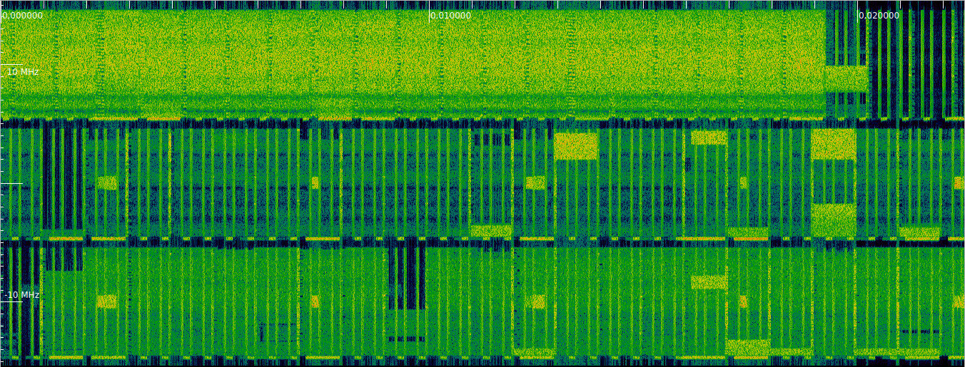
NB-IoT (Narrowband IoT) is a variant of LTE that is intended for low-power low-data-rate IoT devices. It uses a dedicated carrier that is 180 kHz wide (12 subcarriers with the usual LTE 15 kHz subcarrier spacing). This carrier can be placed either inside the regular subcarrier grid of an LTE carrier, in the guardband next to an LTE carrier (which is how it is commonly deployed in Spain), or standalone. In my series of posts about the LTE downlink, I used a recording of the three 10 MHz LTE downlink carriers in the B20 band in Spain made in 2022. A waterfall of this recording is shown here. The three carriers are, in order of increasing frequency, Orange, Vodafone and Movistar. Each of them has an NB-IoT downlink carrier in the lower guardband. The Orange NB-IoT downlink is at 791.3 MHz, so my beacon transmits in the corresponding uplink frequency, which is 832.3 MHz.
The waterfall of the V16 beacon transmission that I recorded is shown here. The whole transmission is comprised of multiple bursts, and it takes slightly less than one second.

NB-IoT uplink fundamentals
NB-IoT has many commonalities with LTE, but there are also large differences, both because everything needs to be crammed into just 12 subcarriers and because of changes to suit better the IoT uses cases (these usually involve simplifications or robustness in bad signal conditions). The main reference for the NB-IoT physical layer is Section 10 in TS 36.211. The resource element grid for NB-IoT is the same as for LTE: 15 kHz subcarrier spacing, 0.5 ms slots composed of 7 symbols, with the first of them having a slightly longer cyclic prefix, 1 ms subframes, and 10 ms radio frames. Both in the uplink and downlink, the NB-IoT subcarriers are shifted up by 7.5 kHz as in the LTE uplink in order to avoid having a subcarrier at DC.
There are only two physical channels in the NB-IoT uplink: the NPUSCH, which is the NB-IoT equivalent of the LTE PUSCH, and is used to transmit user data, and the NPRACH, which is the NB-IoT equivalent of the LTE PRACH and is used for random access of a UE at the start of the cell connection procedure. There is no channel corresponding to the LTE PUCCH, which sends uplink control information. As we will see below, control information is heavily simplified and sent in the NPUSCH. There are two NPUSCH formats: format 1, which sends data, and format 2, which sends control information.
The first transmission in the recording is an NPRACH transmission. The NPRACH is based on a frequency hopping sequence. I will not analyse it in this post. The remaining transmissions are all NPUSCH.
The NPUSCH physical layer is somewhat similar to the PUSCH in the sense that it uses SC-FDMA to improve the waveform PAPR (peak-to-average power ratio) and that some symbols in the middle of the slot are dedicated to a DMRS (demodulation reference signal). The main difference with the PUSCH is that an NPUSCH transmission can occupy 1, 3, 6 or 12 subcarriers. To allow this, NB-IoT introduces the concept of a resource unit, which is what determines which resource elements are allocated to a transport block. For a 15 kHz subcarrier spacing (NB-IoT also supports 3.75 kHz subcarrier spacing, but this is not used in this recording) and frame structure type 1 (which is used in FDD, which is what corresponds to this recording, and IoT NTN TDD), there are the following resource unit shapes:
- For NPUSCH format 1:
- 1 subcarrier x 16 slots
- 3 subcarriers x 8 slots
- 6 subcarriers x 4 slots
- 12 subcarriers x 2 slots
- For NPUSCH format 2:
- 1 subcarrier x 4 slots
The lowest subcarrier of an allocation needs to be divisible by the number of subcarriers in the allocation. Therefore, for 3 subcarriers, the possible allocations are {-6,-5,-4}, {-3, -2, -1}, {0, 1, 2}, {3, 4, 5}, and for 6 subcarriers the possible allocations are {-6, -5, -4, -3, -2, -1}, and {0, 1, 2, 3, 4, 5}.
Single-tone NPUSCH and phase rotation
NPUSCH transmissions allocated to several subcarriers, commonly referred to as multi-tone transmissions, use SC-FDMA as the LTE PUSCH. NPUSCH transmissions allocated to one subcarrier are referred to a single-tone transmissions. In the 3GPP documentation they are also described as SC-FDMA, even though they are a special case in many sections. They are best described as single-carrier \(\pi/2\)-BPSK or \(\pi/4\)-QPSK modulation whose symbol duration matches the OFDM grid (so the first symbol in every 7 is slightly longer). The precise definition is in Section 10.1.5 in TS 36.211. The complex baseband time-domain waveform for a symbol is\[s_{k,l}(t) = a_{k^{(-)},l}\cdot e^{i\phi_{k,l}} \cdot e^{2\pi i(k + 1/2)\Delta f(t – N_{\mathrm{CP},l}T_s)},\qquad 0 \leq t < (N_{\mathrm{CP},l} + N)T_s.\]Here \(k \in \{-6, -5, \ldots, 5\}\) denotes the subcarrier that is used, \(l\) is the slot number, \(a_{k^{(-)},l}\) is the complex BPSK or QPSK symbol, \(\phi_{k,l}\) is a phase rotation term that is defined below, and the exponential on the right hand side is the carrier wave of the \(k\)-th OFDM subcarrier (recall that subcarriers are shifted up in frequency by 1/2 of the subcarrier spacing). The term \(\Delta f\) is the subcarrier spacing, \(N_{\mathrm{CP},l}T_s\) is the cyclic prefix duration and \(NT_s = 1/\Delta f\) is the useful symbol duration.
The phase rotation term \(\phi_{k,l}\) is vaguely related to the 5G NR phase compensation, which I explained in this post. The key remark for why this phase rotation is needed is that if we consider the above formula without this term, then we don’t get a phase-continuous carrier wave. The issue is that the OFDM subcarrier does not advance an integer number of cycles over the symbol duration. More precisely, the phase of this exponential at the end of the symbol minus its phase at the beginning of the symbol is \(2\pi(k + 1/2)\Delta f(N_{\mathrm{CP},l} + N)T_s\), which is not an integer multiple of \(2\pi\).
The phase rotation term is defined as\[\phi_{k,l} = \rho \cdot (\tilde{l} \ \operatorname{mod} 2) + \varphi_k(\tilde{l}).\]The index \(\tilde{l}\) counts over all the slots in an NPUSCH transmission (the details of what exactly counts as a “transmission” are in the TS). The function \(\varphi_k\) is defined recursively as \(\varphi_k(0) = 0\) and\[\varphi_k(\tilde{l}) = \varphi_k(\tilde{l}-1) + 2\pi(k + 1/2)\Delta f(N_{\mathrm{CP},l} + N)T_s\]for \(\tilde{l} > 0\). To motivate this definition, consider the term\[\psi_{k,l}(t) = e^{i\varphi_k(\tilde{l})}\cdot e^{2\pi i(k + 1/2)\Delta f(t – N_{\mathrm{CP},l}T_s)}.\]This is equal to\[e^{i\varphi_k(\tilde{l} – 1)}\cdot e^{2\pi i(k + 1/2)\Delta f(t + NTs)}.\]At \(t = 0\), this has the phase \(\varphi(\tilde{l} – 1) + 2\pi (k + 1/2)\Delta f N T_s\). If compute \(\psi_{k,l-1}((N_{\mathrm{CP},l-1} + N)T_s))\), we also get the same phase. Therefore, we see that this expression \(\psi_{k,l}(t)\) defines a phase-continuous carrier wave piecewise in each of the OFDM symbols, due to how \(\varphi_k(\tilde{l})\) was defined.
The term \(\rho\) is defined as \(\pi/2\) for a BPSK modulation and \(\pi/4\) for a QPSK modulation. Therefore, \(\rho \cdot (\tilde{l}\ \operatorname{mod} 2)\) implements either \(\pi/2\)-BPSK or \(\pi/4\)-QPSK by introducing a phase rotation of \(\rho\) to odd symbols. The goal of using \(\pi/2\)-BPSK and \(\pi/4\)-QPSK instead of BPSK and QPSK is to improve the PAPR by avoiding zero crossings.
Therefore, we have seen that the single-tone NPUSCH modulation can be described in more simple terms as \(\pi/2\)-BPSK or \(\pi/4\)-QPSK with rectangular pulse shape and phase continuous carrier. The more convoluted way in which it is defined in the TS is actually the practical way in which it needs to be treated when using OFDM for modulation or demodulation of this single-tone waveform.
As a final note regarding the resetting of \(\tilde{l}\), note that for a subcarrier spacing of 15 kHz, \(\varphi_k(28)\) is an integer multiple of \(2\pi\), since the accumulated duration of useful symbols and cyclic prefixes is 2 ms, which gives an integer when multiplied by \(\Delta f/2\). This both means that when the TS says that \(\tilde{l}\) is reset exactly does not have much practical importance, and also that the phase rotation terms can be precomputed in a table of 28 entries for each of the 12 subcarriers.
Initial recording analysis and synchronization
The waterfall of this recording, excluding the NPRACH transmission at the beginning, is shown again here. We can clearly see that most NPUSCH transmissions are single-tone. Their spectrum looks like a sinc function, due to the rectangular pulse shaping (which is ultimately caused by the OFDM modulation). However the transmitter has a filter that cuts off the sinc sidelobes outside the 180 kHz bandwidth of the cell, so the sidelobes do not extend forever and the spectrum is technically different depending on which subcarrier is occupied.
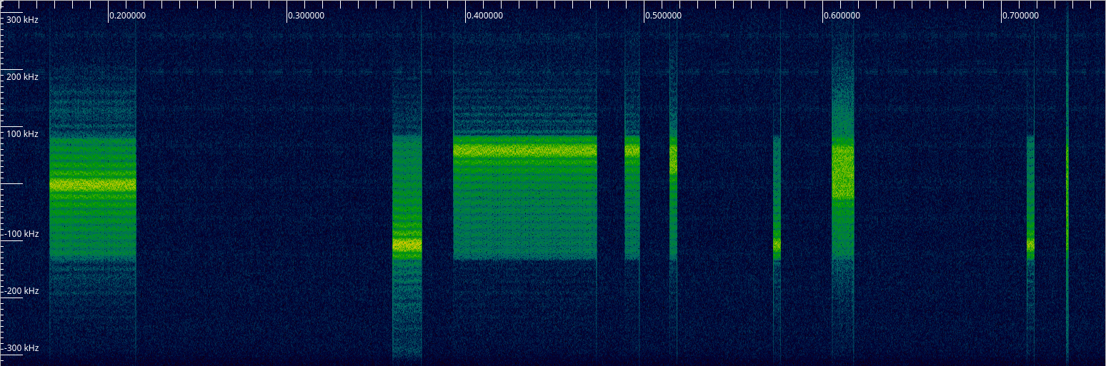
The 5th burst is a multi-tone transmission using 3 subcarriers. The 7th burst is a multi-tone transmission using 6 subcarriers. The last burst is a very brief transmission that uses the 12 subcarriers.
It is easy to perform a coarse frequency synchronization by reading off the centre frequencies of the single-tone transmissions in the waterfall. However, to make use of this technique we need to know which subcarrier index is used for each transmission. To find this, we can take advantage of the fact that the nulls in the sinc spectrum of the transmissions roughly correspond to the subcarrier spacing (roughly rather than exactly because the symbol duration is slightly longer than \(1/\Delta f\) due to the cyclic prefix). Therefore, we can count subcarriers by counting nulls. In this way we see that the second and third transmission use the outermost subcarriers, which are -6 and 5 respectively. The first transmission uses subcarrier 1.
Finer frequency synchronization can be obtained by hand by looking at the time-domain waveform of a single-tone transmission that has been downconverted to baseband. This can also be done after demodulation, by looking at how the phase of the symbols rotates over time.
The following plot shows the first 3 ms of the first transmission after being downconverted to baseband by shifting it down in frequency by \((1+1/2)\Delta f\) plus the carrier frequency offset.
We see that the modulation is \(\pi/4\)-QPSK and that the phase does not rotate visibly, because the carrier frequency offset has already been determined quite accurately. The fact that this is a single-tone \(\pi/4\)-QPSK modulation can also be used to measure the carrier frequency. By computing the 8-th power of the complex baseband time-domain data, we remove the modulation and obtain a CW carrier whose frequency is 8 times that of the residual frequency error.
We can zoom in time to the beginning of this transmission to find the sample where the first symbol begins, which we need to perform demodulation.
Technically speaking, we could demodulate these single-tone transmissions by downconverting them to baseband and accumulating each symbol. However, since we still need OFDM demodulation for multi-tone transmissions, we will use OFDM demodulation for all the NPUSCH transmissions. We perform OFDM demodulation as usual for LTE, by taking into account that the first symbol in each 7-symbol slot has a slightly longer cyclic prefix. To perform OFDM demodulation in a simple way, it is convenient to choose a sample rate such that the useful symbol duration and the cyclic prefix durations are all an integer number of samples. The lowest sample rate for which this happens is 1.92 Msps. I made the recording at 640 ksps, which is more than enough to capture the NB-IoT 180 kHz bandwidth. Therefore, to process the recording I have first used GNU Radio to interpolate the recording by a factor of 3 to obtain 1.92 Msps.
After performing OFDM demodulation, we need to apply the phase rotation terms \(\phi_{k,l}\) that have been introduced above. It is critical that this phase rotation is implemented correctly. An error here will show up as an artificial carrier frequency offset, which will make us tune to the wrong frequency, causing other problems (such as inter-carrier interference). To verify that my phase rotation implementation is correct, I have used several methods to check that the carrier frequency offset has been cancelled out accurately without relying on this phase rotation. If we ensure this and we get a good constellation after applying the phase rotation to the OFDM demodulated symbols, this means that the phase rotation has been implemented correctly.
The first method is to look at the amplitude in each subcarrier after OFDM demodulation. For a single-tone transmission all the power should be in a single subcarrier. A carrier frequency error causes inter-subcarrier interference and makes some power leak to the adjacent subcarriers.
The second method is a frequency estimator that works only with intra-symbol information. It multiplies, in the time domain, the second half of the useful symbol by the complex conjugate of the first half of the useful symbol, integrates over time, and uses the phase of the result to estimate frequency. For single-tone transmissions this gives a frequency estimator that has an aliasing range of \(\pm \Delta f\). Since the nominal subcarrier frequency is \((k + 1/2)\Delta f\), we expect to get an estimate of \(\Delta f /2\) for even \(k\) and \(-\Delta f / 2\) for odd \(k\).
The first single-tone transmission uses subcarrier \(k = 1\), so we expect to get a frequency estimate of -7500 Hz. The estimate for each symbol in the transmission is plotted here.
The values have an average of -7479 Hz, so it would seem that there is still a small frequency error of 21 Hz. However what happens is that the pulse shape is not perfectly symmetric in frequency, because the transmit filter lets through more sinc sidelobes on one side of the subcarrier than on the other. This causes the estimator to be biased. We will see how transmissions that use \(k = -6\) have a larger bias, due to a higher frequency asymmetry.
A useful side-effect of the intra-symbol frequency estimator is that it also serves to fine tune the symbol timing offset. If there is some timing offset, it will cause inter-symbol interference. The estimator will see the interference and the frequency estimates will split into a group above the nominal frequency and a group below the nominal frequency, since the estimate depends on the values of the adjacent symbols. By tweaking the symbol timing offset to minimize the variance of the intra-symbol frequency estimates we can fine tune the symbol time alignment.
Finally, another method of verifying the carrier frequency offset is the analysis of the time-domain \(\pi/4\)-QPSK waveform that has been mentioned above.
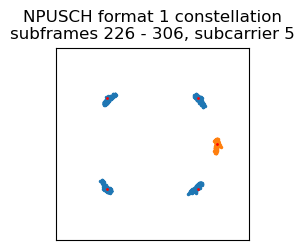
At this point we can perform OFDM demodulation of the first NPUSCH transmission and apply the phase rotation to verify that we obtain a clean QPSK constellation. The constellation for this transmission is shown here. The symbols in orange correspond to the DMRS, which is a pseudorandom BPSK sequence that has already been wiped off in this plot. The details of the DMRS are given below. The DMRS has been used to perform equalization. For each transmission, a constant phase and amplitude is determined using the DMRS and used for equalization of the data and DMRS symbols.
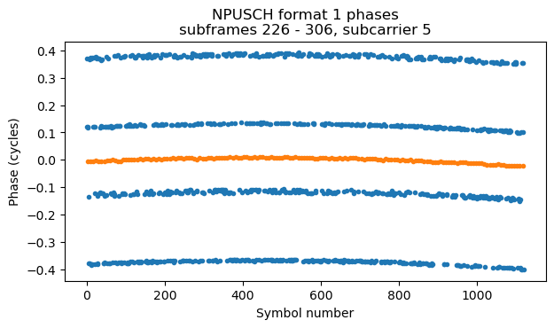
Another plot that is useful is the phase of the symbols over time. By looking at this plot we can tell whether there is any residual frequency error.
Single-tone NPUSCH format 1 DMRS
The DMRS for single-tone NPUSCH is defined in Section 10.1.4.1.1 in TS 36.211. It is constructed differently depending on the NPUSCH format, but both formats use the same underlying pseudorandom sequence. This sequence is defined as\[\overline{r}_u(n) = \frac{1}{\sqrt{2}}(1 + i)(1 – 2c(n)) w_u(n\ \operatorname{mod} 16),\qquad 0 \leq n < M_{\mathrm{rep}}^{\mathrm{NPUSCH}}N_{\mathrm{slots}}^{\mathrm{UL}}N_{\mathrm{RU}}.\]The sequence \(c(n)\) is the usual LTE pseudorandom sequence initialized with \(c_{\mathrm{init}}=35\). I find it rather curious that a constant is used here, since most LTE pseudorandom sequences depend on the cell ID and slot number to reduce inter-cell interference.
The index \(n\) counts slots used by the transmission. The length of what counts as “transmission” is given by \(M_{\mathrm{rep}}^{\mathrm{NPUSCH}}N_{\mathrm{slots}}^{\mathrm{UL}}N_{\mathrm{RU}}\). The number \(N_{\mathrm{slots}}^{\mathrm{UL}}\) denotes the number of slots in a resource unit, which is 16 for NPUSCH format 1 and 4 for NPUSCH format 2, \(N_{\mathrm{RU}}\) is the number of resource units used by the NPUSCH. For format 1 this depends indirectly on the transport block length and the coding rate. For format 2, \(N_{\mathrm{RU}} = 1\). Finally, unlike LTE, NB-IoT supports sending multiple repetitions of the NPUSCH upfront (possibly using different redundancy versions) to improve decoding reliability. The number \(M_{\mathrm{rep}}\) denotes the NPUSCH repetitions. We will see examples of NPUSCH repetition below.
The sequence \(w_u(n)\) is a 16-element vector composed of 1’s and -1’s defined in Table 10.1.4.1.1-1 in TS 36.211. There are 16 possible choices for this sequence depending on the parameter \(u\), which is defined as \(u = N_{\mathrm{ID}}^{\mathrm{Ncell}}\ \operatorname{mod} 16\), unless group hopping is enabled, which is possible to use in NPUSCH format 1. The 16 possible vectors are chosen from a Hadamard orthonormal basis.
In NPUSCH format 1, the middle symbol in each slot is allocated to the DMRS. The DMRS sequence is defined directly as the sequence \(\overline{r}_u(n)\) given above. Since we have just started the signal analysis, we don’t know the physical cell ID \(N_{\mathrm{ID}}^{\mathrm{Ncell}}\). However we can first perform wipe-off of the DMRS ignoring the term \(w_u(n\ \operatorname{mod} 16)\). In our case we see that what remains is an alternating sequence 1, -1, 1, -1, …. This means that group hopping is not used and that \(u = 1\), since \(w_1(n)\) is a vector of alternating 1’s and -1’s. Now that we have determined \(u\), we can wipe off the full DMRS sequence and obtain the constellation plot shown above.
NPUSCH format 2 DMRS
At this point we would like to decode the first NPUSCH format 1 transmission. However we are not yet in a position to do so. We have basically the same challenges that I explained in my post about the LTE PUSCH. The NPUSCH is scrambled with a pseudorandom sequence that depends on the RNTI, the cell ID, and the slot number in which the transmission begins. Without these values we don’t have much chance to decode the NPUSCH, because there are also other parameters that we need to guess, such as the transport block size and the coding rate. In my post about the PUSCH I took advantage of PUCCH formats 2, 2a and 2b, which are used to send CQI to the eNB, to find these values. In NB-IoT there is no direct equivalent of these PUCCH formats, because the UE does not send CQI feedback. However, similar ideas can be applied to the NPUSCH format 2, which is used to send HARQ acknowledgements.
First we will study the DMRS of NPUSCH format 2 and use it to find the cell ID and the radio frame synchronization. In NPUSCH format 2, the 3 symbols in the middle of each slot are allocated to the DMRS. The DMRS sequence is defined as\[r_u(3n + m) = \overline{w}(m) \overline{r}_u(n),\qquad m=0,1,2.\]Here \(n\) counts the slots in the transmission, and \(m\) counts each of the three symbols in the slot. The sequence \(\overline{w}(m)\) is the same as the overlay code for PUCCH formats 1 and 1a. It is defined as \(\overline{w}(m) = e^{2\pi i Mm/3}\). The number \(M\) is computed for each slot as\[M = \sum_{j=0}^7 c(8n_s + j) \cdot 2^j \mod 3,\]where the pseudorandom sequence \(c\) is initialized with \(c_{\mathrm{init}} = N_{\mathrm{ID}}^{\mathrm{Ncell}}\). Therefore, for each slot, an overlay code of three 3rd roots of unity are chosen pseudorandomly based on the cell ID.
Since the overlay code \(\overline{w}(m)\) contains 3rd roots of unity, from looking at a constellation plot it is quite easy to distinguish single-tone NPUSCH format 1 from NPUSCH format 2. In this recording, the second NPUSCH transmission uses format 2 and subcarrier \(k = -6\). Here is a plot of the time domain waveform after being downconverted to baseband. In this plot I am using a slightly different carrier frequency offset than in the plot for the first NPUSCH transmission. I have found that in this recording each transmission requires a small tweak of a few 10s of Hz to the carrier frequency offset, and sometimes also a few samples to the symbol timing offset.
It is quite apparent that the modulation is \(\pi/2\)-BPSK. With a more careful look we can even seen the 3rd roots of unity used by the DMRS. Another thing that is of interest in this plot is that the pulse shape is much uglier than for the previous transmission. The reason is that this transmission uses the lowest subcarrier. Therefore the transmitter filtering has a highly asymmetric effect in the sinc sidelobes of the pulse.
In the amplitude of the subcarriers after OFDM demodulation we can see that the power is concentrated in a single subcarrier, which is a check that the frequency error is small.
However the intra-symbol frequency estimator gives an average value of 7281 Hz, suggesting that there is a frequency error of 219 Hz, which is reasonably large. This error is caused by a bias in the estimator due to the pulse shape distortion.
Since we know how to compute the sequence \(\overline{r}_u(n)\) and the three DMRS symbols in each slot are the same except for the \(\overline{w}(m)\) term, we can wipe off \(\overline{r}_u(n)\) and then find the sequence of values \(M\) that generates the \(\overline{w}(m)\) term in each slot. This sequence is the following.
[0, 1, 2, 2, 0, 2, 1, 0, 2, 2, 2, 2, 2, 2, 0, 2,
 1, 2, 1, 2, 0, 1, 2, 2, 0, 2, 1, 0, 2, 2, 2, 2]
With this information we can now wipe off the full DMRS. After doing this, we get the following constellation and phase versus time plots.
Now we can work with the sequence of values of \(M\) that we have obtained to find the cell ID and the radio frame synchronization. For each cell ID, the sequence of values of \(M\) depends only on the slot number \(n_s\). Therefore, it is a 20-element sequence that repeats periodically. Because this NPUSCH transmission is longer than 20 slots, we have more than 20 values for \(M\), but we can check that the sequence obtained above has period 20, so we only use the first 20 elements. The cell ID is an integer between 0 and 503. For each cell ID we generate the corresponding 20-element sequence of values of \(M\) and find whether the first 20 elements of the sequence we found match this 20-element sequence by applying a circular shift. Each match that we obtain gives a candidate cell ID and slot number \(n_s\), which is obtained from the circular shift used in the match. By running this brute force algorithm we obtain just one candidate: \(N_{\mathrm{ID}}^{\mathrm{Ncell}} = 145\) and \(n_s = 12\). Note that indeed \(N_{\mathrm{ID}}^{\mathrm{Ncell}}\ \operatorname{mod} 16 = 1\) as we had found with the Hadamard vector \(w_u(n)\).
Obtaining the RNTI from NPUSCH format 2
The scrambling sequence used for the data in both NPUSCH formats is initialized with\[c_\mathrm{init} = n_{\mathrm{RNTI}}\cdot 2^{14} + (n_f\ \operatorname{mod} 2) \cdot 2^{13} + \lfloor n_s / 2 \rfloor \cdot 2^9 + N_{\mathrm{ID}}^{\mathrm{Ncell}}.\]This is pretty similar to the LTE PUSCH scrambling sequence, except that the codeword index \(q\) has been replaced by the frame number \(n_f\) modulo 2. This is because NB-IoT does not support two-codeword transmission, but the downlink structure is organized in terms of even and odd frames, so a UE listening to the downlink obtains synchronization to the frame number modulo 2. Since the frame number modulo 2 only has 2 possibilities, we could easily brute force it, but we still need to find the RNTI, which is a 16-bit number. We will use the NPUSCH format 2 transmission to help us.
The NPUSCH format 2 is very simple. It only carries a HARQ acknowledgement, which is a single bit of information: 1 for a positive acknowledgement and 0 for a negative acknowledgement. This bit is encoded into 16 bits by using a repetition code (see Section 6.3.3 in TS 36.212). These 16 bits get mapped into an NPUSCH format 2 resource unit, which has a duration of 4 slots. Each slot has 4 \(\pi/2\)-BPSK data symbols, because the 3 symbols in the middle of the 7-symbol slot are used by the DMRS. This means that if we take the 16 data bits in an NPUSCH format 2 transmission and descramble them, we should find 16 repetitions of the same value if the scrambling sequence was correct.
The NPUSCH format 2 transmission that we are analysing is composed of 8 repetitions of the NPUSCH format 2. We take the first repetition and do a brute force search for each possible value of \(n_{\mathrm{RNTI}}\) and \(n_f\ \operatorname{mod} 2\), noting a candidate whenever we obtain 16 repetitions of the same value after descrambling. In this way, we get the following candidates:
- \(n_{\mathrm{RNTI}} = 53958, n_f\ \operatorname{mod} 2 = 1\)
- \(n_{\mathrm{RNTI}} = 55023, n_f\ \operatorname{mod} 2 = 0\)
- \(n_{\mathrm{RNTI}} = 55957, n_f\ \operatorname{mod} 2 = 1\)
- \(n_{\mathrm{RNTI}} = 57020, n_f\ \operatorname{mod} 2 = 0\)
Here we have a similar challenge to what happened with the PUCCH format 2 Reed-Muller code. The function that maps the 17-bit vector \((n_{\mathrm{RNTI}}, n_f\ \operatorname{mod} 2)\) into the 16-bit NPUSCH format 2 scrambling vector is an affine function. We are requiring that after descrambling we get 16 copies of the same value. This is a system of 15 independent linear equations. Therefore, in the best case (which is when the corresponding affine maps are non-degenerate), we only can expect that the space of solutions of our brute force search is an affine subspace of dimension 2. This is actually what happens, so we get 4 solutions.
Using more repetitions of the same NPUSCH format 2 transmission will not help us. The scrambling sequence is generated independently for each repetition, using the \(n_f\ \operatorname{mod} 2\) and \(\lfloor n_s / 2\rfloor\) corresponding to the start of each repetition. However a moment’s thought leads us to conclude that we would get exactly the same solutions (with \(n_f\) appropriately adjusted for the fact that the repetitions may not happen in the same radio frame). The issue is that if we add to the correct \((n_{\mathrm{RNTI}}, n_f\ \operatorname{mod} 2)\) vector a vector such that the corresponding scrambling sequence is all zeros or all ones, we also obtain another candidate solution. For the same reason, using other NPUSCH format 2 transmissions that happen at a later time will not help either. We could heuristically decide that the HARQ acknowledgement is more likely to be 1 for a positive acknowledgement than 0. This would still leave two candidate solutions.
Obtaining the RNTI from NPUSCH format 1
Now that we have narrowed down the candidates for the RNTI and frame number modulo 2 to only 4 options, we can attempt to use the first NPUSCH format 1 transmission to select only one out of the 4 options. The key idea is something I also used with the LTE PUSCH. Initial transmissions usually have a low coding rate, so the rate matching algorithm repeats some of the bits of the Turbo codeword. We can attempt to descramble the NPUSCH transmission and then check if all the rate matching repetitions have the same value. To do this we need the following parameters, which affect the rate matching algorithm:
- The transport block size.
- The redundancy version index.
- The number of resource units \(N_{\mathrm{RU}}\) occupied by the NPUSCH transmission. What we see as a single transmission might be multiple repetitions of the same transmission.
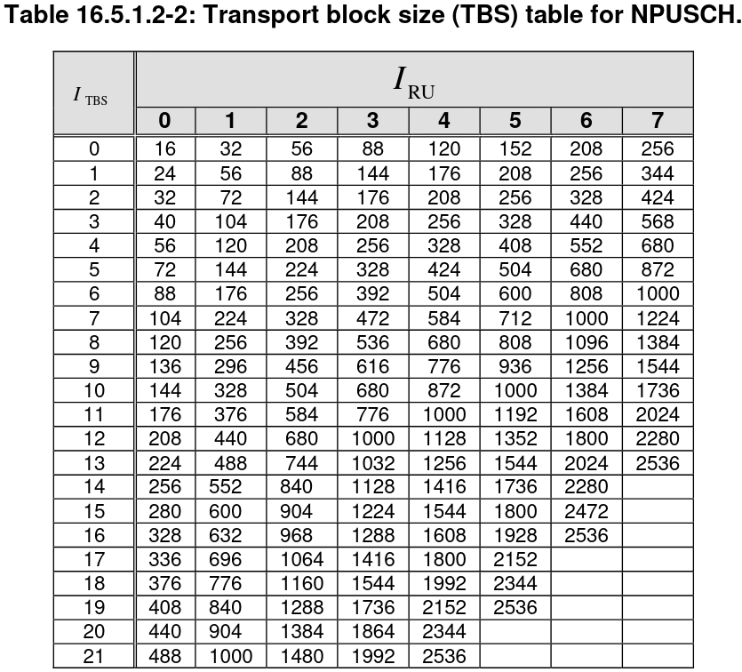
To find the transport block size, we need the following table from TS 36.213. The transport block size is found in terms of two indices: \(I_{\mathrm{RU}}\), which indicates the number of resource units \(N_{\mathrm{RU}}\) used by the NPUSCH transmission, and \(I_{\mathrm{TBS}}\), which is related to the MCS.
The number of resource units \(N_{\mathrm{RU}}\) that can be used for an NPUSCH transmission, and the corresponding index \(I_{\mathrm{RU}}\) is given in this table in TS 36.213.
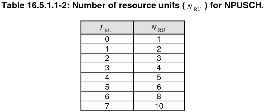
The index \(I_{\mathrm{RU}}\) is transmitted in the scheduling grant in the NPDCCH, but we don’t have access to this information, since we only have a recording of the uplink.
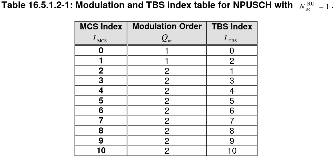
For single-tone NPUSCH, the MCS that are supported are given by the following table. The modulation order \(Q_m\) indicates \(\pi/2\)-BPSK for \(Q_m = 1\) and \(\pi/4\)-QPSK for \(Q_m = 2\). The MCS index is transmitted in the scheduling grant, and this also determines the \(I_{\mathrm{TBS}}\) index.
It is also helpful to know that the number of repetitions of an NPUSCH transmission can be 1, 2, 4, 8, 16, 32, 64, or 128.
The first NPUSCH format 1 transmission occupies 48 subframes, which is 96 slots. Since a single-tone NPUSCH format 1 resource unit has 16 slots, this means that we have 6 resource units in total. Therefore, we could either have one repetition of a 6-resource unit transmission, or 2 repetitions of a 3-resource unit transmission.
We know that the modulation is \(\pi/4\)-QPSK. Since we expect a low coding rate, our candidate for MCS is 2, which corresponds to a TBS index of 1. With this MCS, a 3-resource unit transmission would have a transport block size of 88 bits. A 6-resource unit transmission would have a transport block size of 208 bits.
In the LTE PUSCH post I used the fact that the first PUSCH transmission that happens after PRACH is an RRCConnectionRequest message, which is almost 56 bits long. Looking at the table above, we would see that with MCS 2 this only needs 2 resource units. However, as we will see, the NB-IoT RRC connection request message is slightly longer than the LTE message, which is why the next larger transport block size, which is 88 bits, is needed.
For the first transmission of a transport block, redundancy version 0 is used. Therefore, we use a transport block size of 88 bits, a redundancy version of 0, and a size of 3 resource units for our test. When generating the scrambling sequence, we need to account for the time that has passed between the NPUSCH transmission in which we found \(n_s = 12\) and this transmission, which we see that it starts at \(n_s = 8\). This test reduces the candidate set to just one candidate: \(n_{\mathrm{RNTI}} = 53958\), and \(n_f\ \operatorname{mod} 2 = 0\) (where \(n_f\) is referred to this NPUSCH transmission).
Decoding NPUSCH format 1
We can now decode the first NPUSCH format 1 transmission. The way in which the NPUSCH format 1 transport block is encoded is essentially identical to the LTE PUSCH, except that there are no CQI and RI bits embedded in the transmission, which greatly simplifies things. I have basically used the same code to perform channel decoding.
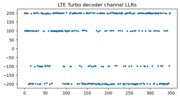
The following plot shows the LLRs after inverting the rate matching algorithm. The LLRs around ±200 correspond to bits that have been transmitted twice.
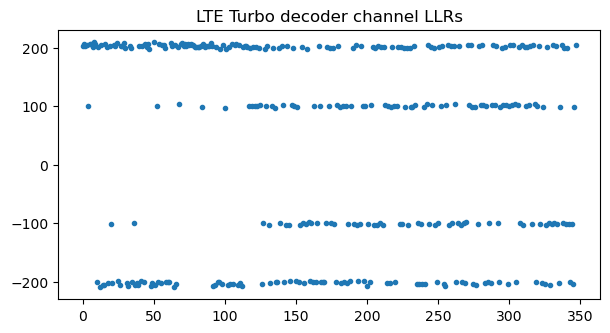
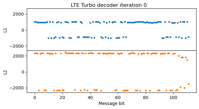
Since there are no bit errors, the Turbo decoder is able to obtain a correct decode in just one iteration.
At this point the CRC-24 of the transport block can be checked to verify that decoding is successful, and the MAC PDU is written to a PCAP file for analysis with Wireshark. The following screenshot (click on it to view it in full size) shows the PDU dissected in Wireshark. It is a CCCH message that contains an rrcConnectionRequest-r13 message. We can see that the RRC Connection Request in NB-IoT is slightly different and longer than in LTE. Besides giving the TMSI and the establishment cause, the UE also gives some details about its physical layer support. In this case we can see that the establishment cause is mo-Data (mobile originating data), which makes sense, because the V16 beacon wants to send some data to the network. The UE supports multi-tone and multi-carrier operation, and early contention resolution, but it does not report a measurement of CQI for the NPDCCH.
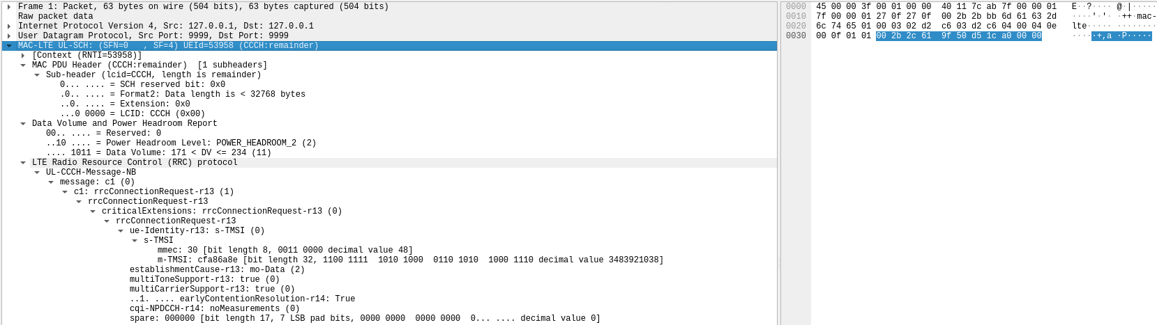
Another novelty in this MAC PDU is the Data Volume and Headroom Report control element. This is an exclusive feature of NB-IoT. It is described in Section 6.1.3.10 in TS 36.321. Using this element, the UE is already reporting to the eNB that it has between 172 and 234 bytes of data to send.
Because of the additional information compared to the LTE RRC connection request, the NB-IoT RRC connection request needs 71 bits, so there are 17 spare bits at the end of the ASN.1 message to fill up the 88-bit transport block.
This NPUSCH format 1 transmission has two repetitions using 3 resource units each. The second repetition uses redundancy version 2. In NB-IoT, the redundancy version index can only be 0 or 2, and it alternates with each repetition of a transmission. We can descramble the second repetition and perform inverse rate matching with redundancy version 2, obtaining the following LLRs. Performing Turbo decoding of this repetition we obtain exactly the same RRC connection request PDU.
Decoding the remaining NPUSCH transmissions
The following plot gives an overview of the NPUSCH transmissions in the recording. It shows the average power in each subframe and subcarrier, starting with the first NPUSCH transmission. As we will see below, all the transmissions in subcarrier -6 are NPUSCH format 2 that contain a positive HARQ acknowledgement. The rest of the transmissions are NPUSCH format 1.
We have already seen that the second transmission is 8 repetitions of NPUSCH format 2. Since we know know the RNTI and frame number modulo 2, we can descramble the transmission and find that it is a positive HARQ acknowledgement (which is encoded as the value -1).

The third transmission is a rather long NPUSCH format 1 transmission. It lasts 80 subframes and occupies the highest subcarrier. In the plot of the symbol phases versus time we can see that there is some frequency drift, because the phases look like a parabola. This could be equalized out using the DMRS, but here I am using a constant phase equalization for all the duration of each transmission.
Since this transmission occupies 10 resource units, it could either be 2 repetitions of a 5 resource unit NPUSCH, or a single 10 resource unit NPUSCH. We also need to find the MCS to perform decoding. We can perform trial and error with all the options until we obtain a successful decode for one of them. It turns out that this is a 10 resource unit transmission using MCS 10. This is the largest NPUSCH allocation in terms of resource units, and the highest MCS for single-tone NPUSCH, so the corresponding transport block size of 1736 bits is the largest that can be transmitted with single-tone.
The following plot shows the LLRs after inverting the rate matching algorithm. Since the coding rate is high, many bits in the Turbo codeword have been punctured by rate matching, specially in the last two thirds of the codeword.
It makes sense that the UE got this rather large uplink grant, since in the Data Volume and Headroom Report it said that it had probably enough data to fill it, and in fact it does. Looking at the decoded MAC PDU in Wireshark, we see that it is an UL-DCCH message in SRB 3 that contains an rrcConnectionSetupComplete-r13 message. We do not see the messages sent on the downlink by the eNB, but from what we see on the uplink and the knowledge of how a regular LTE connection works (see my post about the LTE MAC layer), we infer that this message is a response to an RRC connection setup message sent by the eNB.
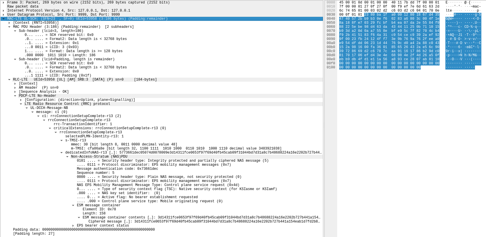
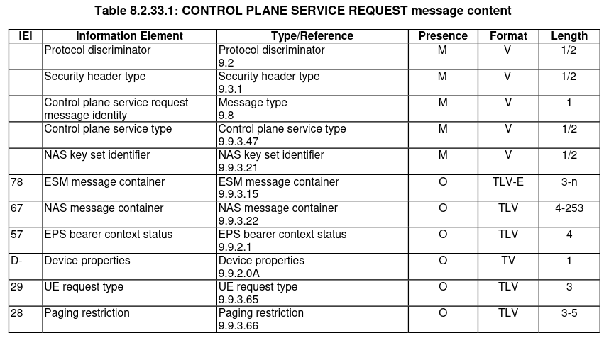
As in LTE, the RRC connection setup complete message embeds a NAS PDU. In addition, it also indicates the UE S-TMSI. The NAS PDU contains a control plane service request message. This message forms part of a mechanism callled control plane CIoT EPS optimization. I will describe this in more detail below, but the main idea is that it is a way for an NB-IoT UE to send some data to the network without having to go through the usual hoops to establish a user plane data connection. The control plane service request message contains a 158 byte encrypted message which is what presumably contains the V16 beacon GNSS position and other data.
The NAS PDU also contains an EPS bearer context status. I haven’t expanded this in Wireshark because it doesn’t fit in the screen. It simply says that the EBI(5) bearer context is active and the remaining bearer contexts are inactive.
The next transmission is a brief NPUSCH format 1 transmission using subcarrier 5. It occupies 8 subframes, which is just one single-tone resource unit.
As before, the MCS turns out to be 10, so the transport block size is 144 bits. It looks like the eNB now knows that the UE has a relatively good channel, and therefore it is scheduling it with a high MCS.
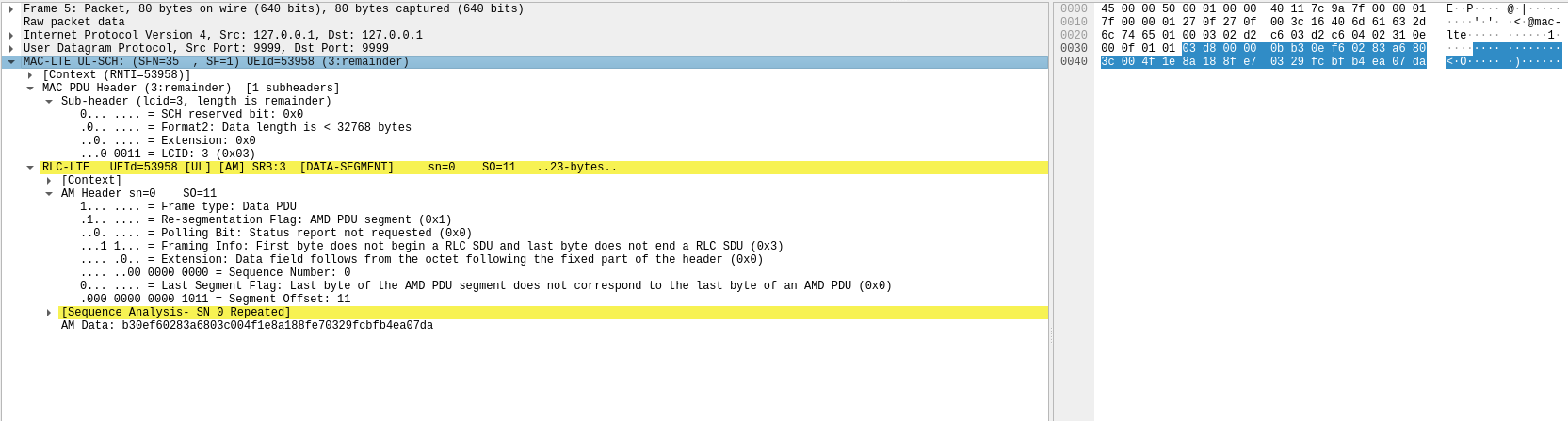
The decoded MAC PDU can be seen here in Wireshark. We see that it contains the first AM fragment of an RLC SDU in SRB 3. Wireshark warns us that the sequence number of this AM PDU, which is zero, is repeated. The RRC connection setup complete message in the previous transmission also used this AM sequence number. We can even see that the AM data in this PDU is the same as the beginning of the RRC connection setup complete message. Therefore, this PDU is a retransmission of the RRC connection setup complete message.

We can infer that the UE has received a HARQ acknowledgement for its transmission of the RRC connection setup complete message. Otherwise I think that it would be trying to send that same transport block with redundancy version 2. However, it has not received yet an AM ACK from the RLC layer, and the AM PDU was sent with the polling flag enabled. Therefore it makes sense that an RLC retransmission is initiated if an ACK is not received. Nevertheless it seems that the retransmit timer is configured too short here. The retransmission is done 96 ms after the orginal transmission, but the original transmission took 80 ms of air time to send. So this retransmission is really happening too soon.
This MAC PDU also has a short BSR control element that says that the UE has between 172 and 200 bytes of data to send. This makes sense. Since the UE got a small uplink grant, it could only send 11 bytes of the large RRC connection setup complete message.
The next transmission is the first multi-tone NPUSCH format 1 transmission that we see in the recording. It occupies subcarriers 3, 4, 5. Decoding multi-tone NPUSCH format 1 has the following differences compared to single-tone NPUSCH format 1:
- The phase rotation is not applied.
- Multi-tone NPUSCH format 1 uses SC-FDMA in the same way as the LTE PUSCH. After OFDM demodulation and equalization, an IFFT needs to be applied to data symbols to invert the SC-FDMA precoding (the DMRS does not use SC-FDMA).
- The DMRS is constructed differently. The details are given in a section below.
- Like in the LTE PUSCH, the transport block is interleaved to be mapped first in time and then in frequency. This means that adjacent symbols get mapped to symbols that are adjacent in time. In NPUSCH this interleaving is done independently in each resource unit.
Because multi-tone transmissions are more susceptible to symbol timing offset (which causes time-domain inter-symbol interference in the SC-FDMA modulation), in these transmissions we have to tweak the timing offset by looking at whether there is a phase versus frequency slope in the DMRS.
The following plots show the constellation after demodulation (including inversion of the SC-FDMA precoding) of the multi-tone transmission. In the plot of phase versus time, the x-axis corresponds to the OFDM symbol number, so symbols transmitted in different subcarriers at the same time are shown on the same x-axis value.
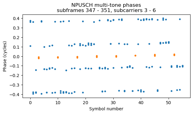
This transmission occupies only 4 subframes, which corresponds to a single 3-tone resource unit. Multi-tone NPUSCH can use QPSK and 16QAM. For QPSK the allowed range of \(I_{\mathrm{TBS}}\) indices is between 0 and 13, and it corresponds directly to the MCS. For 16QAM (which is not used in this recording), the allowed range of \(I_{\mathrm{TBS}}\) is between 14 and 21 and it is indicated using a dedicated 16QAM MCS field in the DCI. In this case, MCS 13, which is the highest for QPSK is used. This gives a transport block size of 224 bits.
The decoded MAC PDU dissected in Wireshark is shown here. This is the second AM fragment of the RRC connection setup complete retransmission. The UE is able to send the next 23 bytes of the message in this fragment.
The next transmission happens some time later. It is an NPUSCH format 2 transmission using the lowest subcarrier. It occupies 4 subframes, so it is actually two repetitions. Decoding it we see that it contains a positive HARQ acknowledgement. The constellation and phase versus time for this transmission as shown here.
Next we have a multi-tone NPUSCH format 1 transmission that uses subcarriers 0, 1, 2, 3, 4, 5. The transmission occupies 12 subframes, which is 6 resource units of 6-tone NPUSCH.
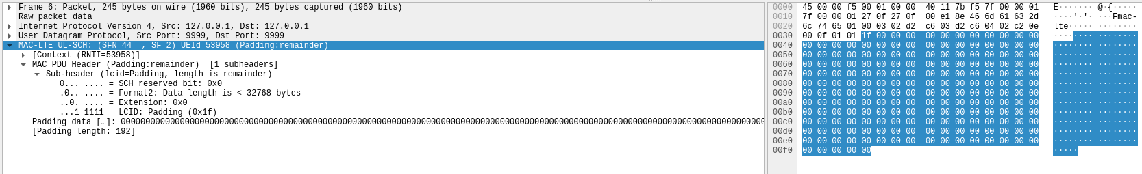
This transmission also uses the highest MCS for QPSK, MCS 13. It is a single repetition of a 6-resource unit transport block, rather than two repetitions of a 3-resource unit transport block. The corresponding transport block size is 1544 bits. Dissecting the MAC PDU in Wireshark we see that it only contains padding. What has happened here? Since the UE had reported in a short BSR that it had data to transmit, it makes sense that it got this relatively large uplink grant to finish transmitting the rest of the data. However, we have seen that the UE has received something on the downlink before this tranmission, because it has sent a positive HARQ acknowledgement. We infer that what the UE has received is the AM ACK for the original RRC connection setup complete message. Therefore, it does not need to retransmit this message anymore, and it does not have anything to be sent in its uplink grant, so it fills it with padding.
The next transmission happens some time later and is an NPUSCH format 2 transmission in the lowest subcarrier. As usual, this is two repetitions of a positive HARQ acknowledgement.
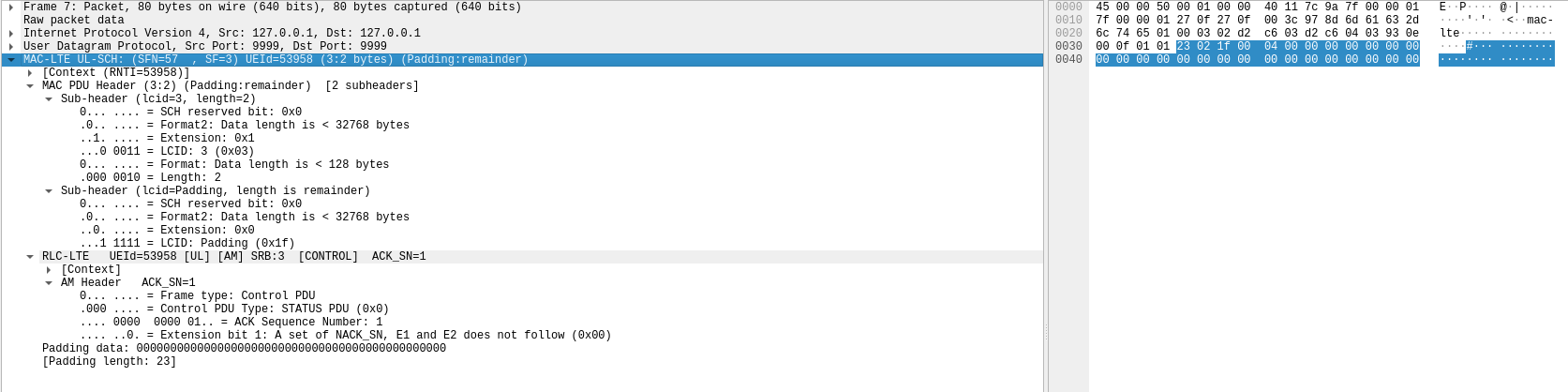
The last NPUSCH transmission is a multi-tone NPUSCH format 1 transmission that uses all the 12 subcarriers and has only one subframe of duration, which corresponds to one resource unit. With 12 subcarriers in use, getting the symbol timing offset right is more critical. Even changing it by one sample (at 1.92 Msps) will give noticeably worse results, although I haven’t needed to implement a fractional delay at OFDM equalization to perform sub-sample timing offset. The constellation and phases for this transmission are shown here.
The MCS for this transmission is also 13. As we have seen earlier, this gives a transport block size of 224 bits for one resource unit. The MAC PDU is just an AM ACK. We infer that was has happened is that the network has sent a reply to the control plane service request that the UE sent in the RRC connection setup complete message. That reply has been acknowledged at the HARQ level in the previous transmission, and is now acknowledged at the RLC layer in this MAC PDU.
In summary, we see that, ignoring the spurious AM retransmission, the conversation in this recording is quite simple:
- The UE sends PRACH
- After a reply by the eNB (which we infer), the UE sends an RRC connection request message indicating its S-TMSI and NB-IoT capabilitites
- We infer that the eNB sends an RRC connection setup message that configures the RRC layer
- The UE sends a positive HARQ acknowlegement as a reply to the RRC connection setup complete message
- The UE sends an RRC connection setup complete message. This message includes a control plane service request message for the NAS, which is used by the control plane CIoT EPS optimization (described below).
- We infer that the eNB sends an AM ACK for the RRC connection setup complete message
- The UE sends a positive HARQ acknowledgement for this AM ACK
- We infer that the eNB sends a reply to the control plane service request
- The UE sends a positive HARQ acknowledgement for this reply
- The UE sends an AM ACK for this reply
The list of MAC PDUs shown in Wireshark also provides a good summary of the conversation.

Multi-tone NPUSCH DMRS
The multi-tone NPUSCH format 1 DMRS occupies the central symbol in each slot. The DMRS sequence is constructed as\[r_u(n) = e^{i\alpha n} e^{i\phi_u(n)\pi/4},\qquad 0 \leq n < N_{\mathrm{sc}}^{\mathrm{RU}},\]where \(N_{\mathrm{sc}}^{\mathrm{RU}}\) denotes the number of subcarriers per resource unit, so \(n\) indexes the subcarriers occupied by the NPUSCH. Note that the DMRS sequence does not depend on the slot number \(n_s\), so it is always the same.
The function \(\phi_u(n)\) takes the values \(\pm 1, \pm 3\), so the \(e^{i\phi_u(n)\pi/4}\) term corresponds to symbols drawn from a QPSK constellation. This function is defined in terms of tables that depend on the number of subcarriers allocated to the NPUSCH and on the index \(u\). Unless overridden by higher layers, the index \(u\) is chosen as:
- \(u = N_{\mathrm{ID}}^{\mathrm{Ncell}} \mod 12\) for 3 subcarriers
- \(u = N_{\mathrm{ID}}^{\mathrm{Ncell}} \mod 14\) for 6 subcarriers
- \(u = N_{\mathrm{ID}}^{\mathrm{Ncell}} \mod 30\) for 12 subcarriers
The term \(e^{i\alpha n}\) represents a cyclic shift that can be set by higher layers to a value of the form \(\alpha = 2\pi n_{\mathrm{cs}} / 12\), with integer \(n_{\mathrm{cs}}\), but it defaults to \(\alpha = 0\).
In this recording, we can see that the index \(u\) is chosen in terms of the cell ID as indicated here, and \(\alpha = 0\). With this knowledge we can generate and wipe-off the DMRS in multi-tone NPUSCH transmissions.
Control plane CIoT EPS optimization
The control plane CIoT EPS optimization is part of some features introduced in the LTE network mainly to support NB-IoT use cases. They are intended to optimize small data transfers by removing some setup steps that are needed in regular LTE connections. In particular the control plane CIoT EPS optimization allows sending user data or SMS encapsulated in a NAS message. Therefore, data can be sent as soon as an RRC connection has been established, by encapsulating it in the RRC connection setup complete message. This is important for battery powered IoT sensors, which need to wake up periodically and send a small amount of data.
The CIoT EPS optimizations are introduced in Section 4.10 in TS 23.401. The functional description for data transport in the control plane CIoT EPS optimization is given in Section 5.3.4B in that TS. This section includes a flow for mobile originated data transport in control plane CIoT EPS optimization with P-GW connectivity, which is shown here. I believe this is what is being used by the V16 beacon. However this section does not explicitly refer to the control plane service request NAS message. It only says “The UE establishes a RRC connection or sends the RRCEarlyDataRequest message as defined in TS 36.300 and sends as part of it an integrity protected NAS PDU. The NAS PDU carries the EPS Bearer ID and encrypted Uplink Data.”

with P-GW connectivity, taken from TS 23.401
The procedure for using a control plane service request message for the control plane CIoT EPS optimization is defined in Section 5.6.1.2.2 in TS 24.301. Section 5.6.1.1 describes the cases in which a service request procedure is invoked by the UE. The case applicable here is “b) the UE, in EMM-IDLE mode, has pending user data to be sent;”. In Section 6.6.4 there are more details about the transport of user data via the control plane procedure. This section says that an ESM data transport message is used to encapsulate user data. If the UE is in EMM-IDLE mode, it shall initiate the procedure by sending the ESM data transport message included in a control plane service request message. It seems that this is what is happening here. The control plane service request includes an encrypted ESM message, which is probably this ESM data transport message.
The format of the control plane service request message is given in Section 8.2.33 in TS 24.301. Except for some missing optional fields, this matches what we see in Wireshark.
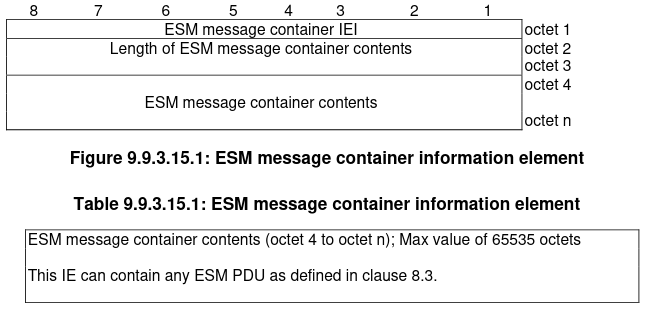
The ESM message container information element is defined in Section 9.9.3.15. It also matches what we see in Wireshark.
ESM message container format, taken from TS 24.301
The ESM data transport message is defined in Section 8.3.25.
We cannot see this message structure in Wireshark because the ESM message container contents are encrypted. Section 4.4.5 in TS 24.301 says that “The UE shall partially cipher the CONTROL PLANE SERVICE REQUEST message by ciphering the value part of the ESM message container IE or the value part of the NAS message container, using the ciphering algorithm of the current EPS security context.”
Conclusions
In this post I have shown how NB-IoT uplink transmissions can be decoded without access to the scheduling grants in the downlink control information by using NPUSCH format 2 transmissions to find the RNTI, the cell ID, and the synchronization to the two radio frame structure of NB-IoT.
I have decoded all the NPUSCH transmissions done by a V16 beacon in a short burst some time after it had been powered on and had already obtained its GNSS position. These NPUSCH transmissions connect to the RRC and send a user data message to the network by using the control plane service request message as defined by the control plane CIoT EPS optimization. This allows the beacon to send a small amount of data and receive a reply without having to fully establish a network connection.
The user data is included in an ESM data transport message, which is encrypted with an EPS security context. Presumably the V16 beacon has authenticated to the network and set up this security context the first time that it transmitted after being powered on. In fact we can see that the NAS PDU containing the control plane service request message has a sequence number of 5. This sequence number is used as part of the EPS security context IV, so this shows that the UE and the NAS have already exchanged a few messages in this security context. It would be interesting to make a recording that contains both the NB-IoT downlink and the uplink since the beacon is powered on, to be able to see how the full conversation works.
Something interesting about these beacons is that they use an NB-IoT network to send the data. Rather than screaming an emergency message into the void without having any feedback, with the hopes that someone gets the message, they use the cellular network for reliable delivery. In fact we have seen in this recording how acknowledgements and retransmissions at different layers of the protocol stack work.
Having feedback in emergency beacons can be quite important. For instance, EPIRBs really scream an emergency message into the void, hoping that it gets picked up by LEO and MEO satellite transponders and decoded at a groundstation. The Galileo system is going to great efforts to provide a SAR return link for these beacons through the navigation message in the Galileo open service broadcast signal. The return link can be used to inform to a user that their distress call has been received and processed by the mission control center and responders.
Since V16 beacons use the cellular network, we get a return link for free. However the beacon does not have a user interface to communicate anything to the user. This seems a missed opportunity to communicate basic information, such as lack of cellular network connectivity, lack of GNSS signal, and successful delivery of the emergency message. Some LEDs or a small status LCD would be an obvious option, but because the beacon strobe light is so bright, this does not seem a good idea. Perhaps these status could be communicated with audio signals. Or maybe even BLE, since most users will also have a smartphone at hand during an emergency and BLE is also ubiquitous in cars these days. These beacons have an MSRP of 30 to 40€, so it seems that these small additions could still fit into the manufacturing costs.
Code and data
The code and data used in this post can be found in this repository. This contains the SigMF recording of the beacon transmission (sigmf-data, sigmf-meta), the Jupyter notebook used for decoding, the PCAP containing the decoded MAC PDUs, and the GNU Radio flowgraph used for resampling the IQ data.
One comment