In my previous post I spoke about the recording I made of the X-band telemetry signal of Hera with the Allen Telescope Array shortly after it was launched. Despite the lack of publicly available accurate ephemerides at the time of launch, I managed to track the spacecraft by hand and decode a good amount of telemetry frames. In this post I will do an in-depth analysis of the telemetry.
TM Frames
As other ESA missions, Hera transmits CCSDS TM Space Data Link frames instead of the newer AOS frames. The frames use spacecraft ID 0xb5, which is registered to Hera in the SANA registry. They contain an Operational Control Field, but no secondary header. There are three virtual channels in use in my recording: Virtual Channel 1, which contains real time telemetry, Virtual Channel 3, which is a replay of recorded telemetry, and Virtual Channel 7, which is only-idle-data.
In the previous post I showed that Hera changed the baudrate from around 60 kbaud to around 322 kbaud at some point in my observation. Virtual Channel 3 is only used with the 322 kbaud downlink. As we will see below, it looks that the baudrate was increased to allow having enough bandwidth to send a replay of the telemetry recorded since launch, the beginning of which hadn’t been seen by any groundstation before.
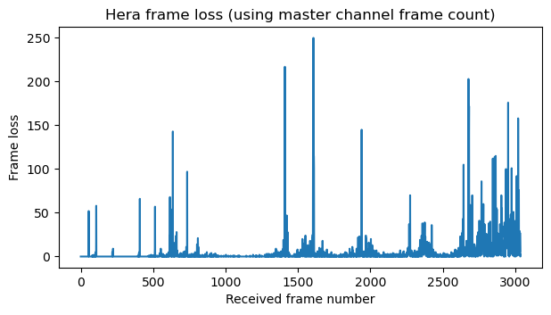
The following figure shows the frame loss calculated using the master channel frame count in the TM Primary Header. Since the frame count is an 8-bit integer, this frame loss is only correct modulo 256 frames. The large spikes in the plot probably correspond to more than 256 frames, because they happened in moments when the SNR was bad due to wrong antenna pointing. The frame loss is only zero in several intervals during the first 500 received frames or so, which correspond to the 60 kbaud signal. For the 322 kbaud signal the frame loss is small at times, but never zero. This shows that the SNR in the recording was quite marginal to decode correctly.
The next plot shows the relative usage of each virtual channel. After 500 frames we can see that Virtual Channel 3 appears. This corresponds to the change to 322 kbaud and the transmission of a replay of recorded telemetry. Virtual Channel 7 goes almost to zero at this point, because all the spare bandwidth is used by Virtual Channel 3. The relative usage of Virtual Channel 1 changes, but this is only because of the change in baudrate. As we will see, the rate at which frames are sent on this virtual channel is roughly the same regardless of the baudrate change. Once the transmission on Virtual Channel 3 stops, Virtual Channel 7 occupies all the remaining bandwidth.
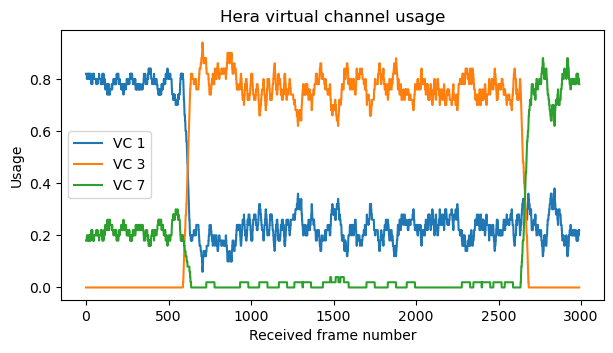
When interpreting this plot it is good to remember that I didn’t record the change from the 60 kbaud signal to the 322 kbaud signal. I lost the spacecraft signal for approximately 20 minutes, and the change happened while I was searching for it.
Virtual Channel 1
Virtual Channel 1 contains CCSDS Space Packets that use ECSS PUS protocol version 2 (which corresponds to ECSS-E-ST-70-41C). This is a newer version than what JUICE and Euclid use, which is PUS version 1 (although PUS version 2 was published in 2016, so it isn’t really new). All the Space Packets have a secondary header, as mandated by PUS, except for the packets in APID 0, which are PUS time report packets, which do not have a secondary header, and APID 2047, which are idle packets.
Regular PUS packets contain a 48-bit timestamp that counts \(2^{-16}\) second units. The epoch according to the Hera SCLK SPICE kernel is 7.8155681846584E+08 TT seconds since the J2000 epoch. This corresponds to 2024-10-06T19:05:49.281 UTC, which is a somewhat strange epoch because it isn’t any round number. This is some time before the launch, which was at 2024-10-07T14:52:11 UTC. Time report packets contain a 56-bit timestamp that counts \(2^{-24}\) second units using the same epoch.
This plot shows which APIDs are active over time. APID 0 should be active all the time at a constant rate, so the gaps in which it disappears correspond to moments when the signal was too weak.
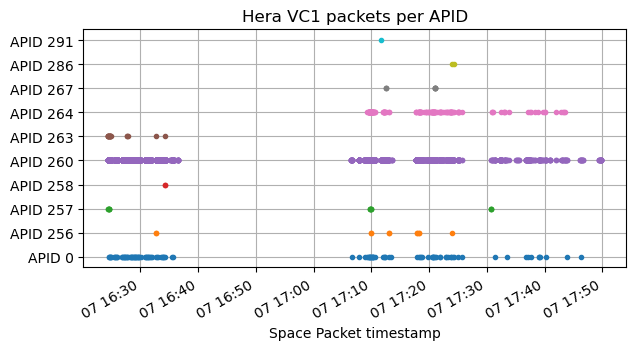
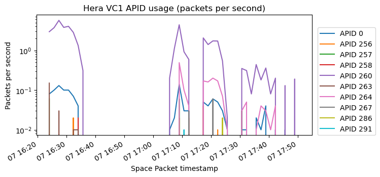
The next two plots show the number of packets per second and bytes per second transmitted on each APID. Due to frame loss, this should be interpreted with some care. For instance, APID 0 should have a roughly constant rate if there was no frame loss. Nevertheless, we can easily see that APID 260 contains most of the data, followed by APID 264 (which is only active in the 322 kbaud signal). Other APIDs only send a few packets when some particular event happens.
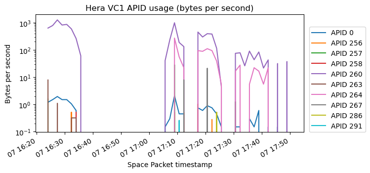
APID 0
APID 0 contains time report packets. The first two bytes of these packets are 0x032f. PUS v2 doesn’t describe the format of these packets, unlike PUS v1, which describes them in Appendix C.3. If we use the information in PUS v1 to interpret these bytes, we see that the time report packets are sent every 128 Virtual Channel 1 frames and that the format of the timestamp is 56 bits with \(2^{-24}\) second units, as I’ve described above. Interestingly, these time report packets do not contain a CRC-16, unlike the rest of the PUS packets. Comparing with the time report packets of previous ESA missions, Euclid didn’t use a CRC-16, while JUICE did.
APID 256
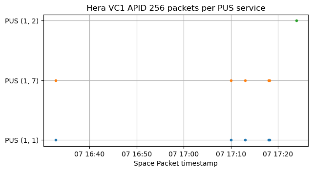
APID 256 contains a few packets from the TM[1,1], TM[1,7] and TM[1,2] PUS services. These are, respectively, “successful acceptance verification report”, “successful completion of execution report”, and “failed acceptance verification report” in the “request verification service”. This service was formerly known as the “telecommand verification service” in PUS v1. Packets in this service are spacecraft responses confirming the reception and execution of telecommands. The packets contain the Space Packet Primary Header (minus the size field) of the corresponding telecommand packet. In all the TM[1,*] frames of Hera, the APID of the telecommand is the same as the APID in which the TM[1,*] report was sent.
The following shows the packets and their corresponding PUS service. Each TM[1,1] packet indicating that a telecommand has been accepted has a corresponding TM[1,7] packet shortly after indicating that the telecommand has been executed. There is a single TM[1,2] packet indicating that a telecommand has been rejected.
APID 257
Besides TM[1,1] and TM[1,7] packets, APID 257 contains also the following PUS services:
- TM[12,9] parameter monitoring definition report (on-board monitoring service)
- TM[12,28] functional monitoring definition status report (on-board monitoring service)
- TM[19,7] event-action status report (event-action service)
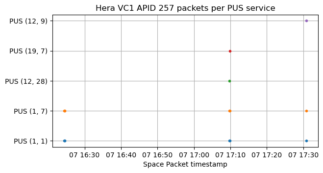
TM[1,1] and TM[1,7] packets correspond to APID 257 telecommands.
The TM[12,9], TM[12,8] and TM[19,7] packets are sent between a TM[1,1] and TM[1,7] packet, so it is clear that they are sent as a consequence of the telecommand execution.
According to the PUS standard, the payload of TM[12,9] packets is structured in the following way. It is somewhat tricky to parse this packet, because some fields are optional and the widths of some fields are not fixed by the standard (the transmitter and receiver are supposed to agree on these choices).
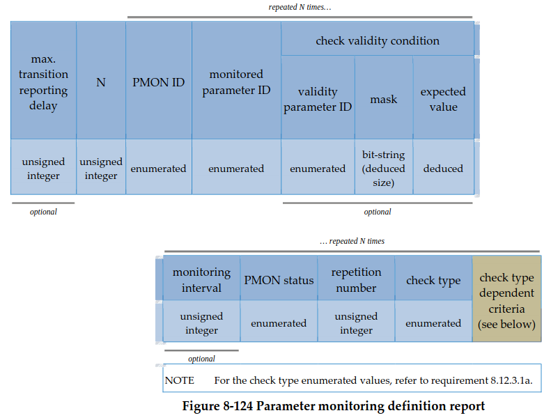
The N field is 32 bits wide and contains the value 1, so there is only one record in this packet. The record in hex is
045a333e1e4400000000000000ff000000000000000200
0100000601c03900000000000009d9405040000000000009d9
With some guesswork, I have determined that the mask for the check validity condition is 000000000000ff00, the expected value for the check validity condition is 0000000000000200, the PMON status is 01, the repetition number is 000006 and the check type is 01. The check type and PMON status correspond to limit checking and unchecked respectively.
For a check type of limit checking, the check type dependent criteria are structured as follows.
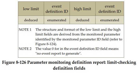
In this case, the event definition ID is 09d9 for both limits, and the values of the limits are float64 values of -25.0 and 65.0 for the low and high limit.
The structure of the payload of TM[12,28] packets is organized in the following way.
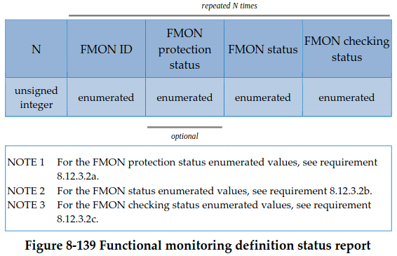
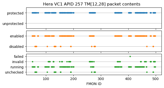
In this case, the value N is a 32-bit integer. The FMON ID is a 16-bit integer. The FMON protection status is included and occupies one byte. The FMON status and the FMON checking status are one byte. The meanings of the FMON protection status, FMON status and FMON checking status values are given in the PUS standard, so we can make the following plot with the contents of this packet.
The structure of the payload of TM[19,7] packets is shown here.
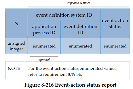
In this case, field N is a 32-bit integer, the application process ID is present and uses 16 bits, the event definition ID also uses 16 bits, and the event-action status uses one byte. Most of the APIDs for the events in the Hera packet are 263, but there are also a few for 1079 and 1159. The event status for most of the events is 1 (enabled), but there are a few with status 0 (disabled).
Something else of interest about this APID is that, while in the other APIDs the destination ID in the PUS header is always zero, this APID contains some packets with a non-zero destination ID. These are the first three pairs of TM[1,1] and TM[1,7] packets, which have a destination ID of 257, and the last TM[1,1], TM[12,9], TM[1,7] triplet, which has a destination ID of 287. The other packets in the APID have a destination ID of zero.
APID 258
APID 258 only contains a TM[1,1] packet and a TM[1,7] sent in relation to a telecommand using the same APID.
APID 260
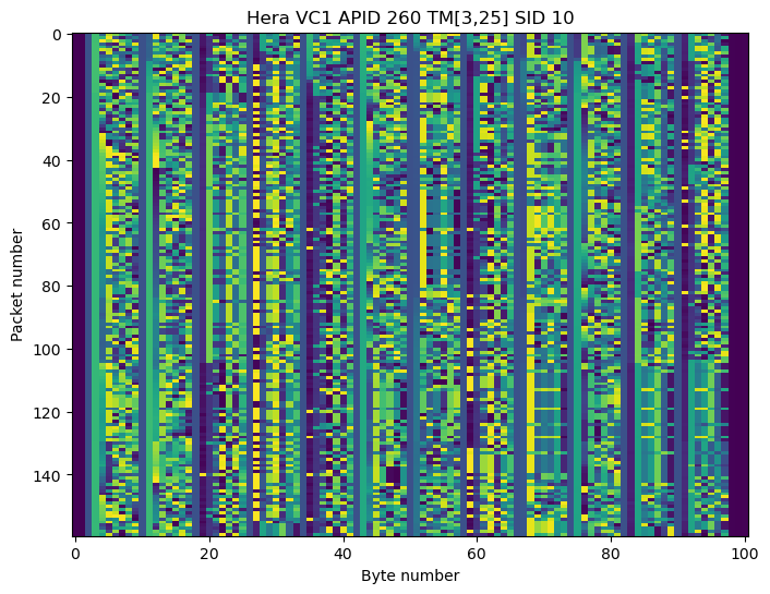
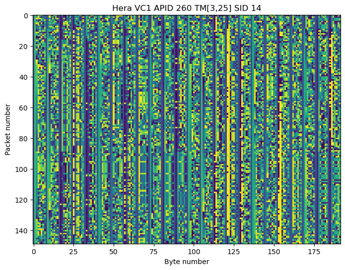
APID 260 contains TM[3,25] packets. These are housekeeping parameter reports in the housekeeping service, which is PUS’s way of saying “telemetry variables”. Each packet begins by a 16-bit SID (structure ID) which identifies which set of telemetry variables are contained in the packet. Within each SID, all the packets have the same size and structure.
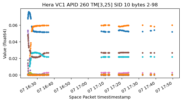
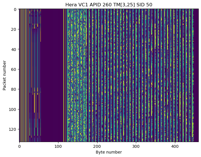
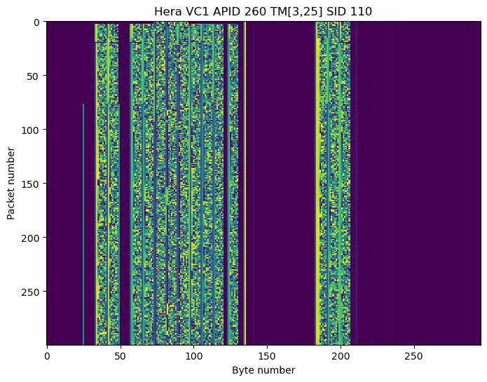
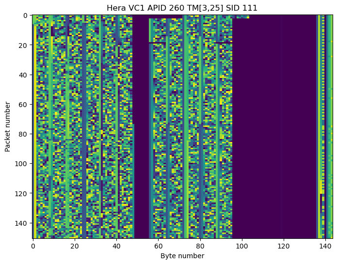
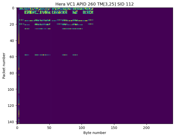
The following plots are the raster maps of some of the SIDs. It is apparent that they contains float64 values. The full list of plots for all the SIDs is in the Jupyter notebook.
I have found and plotted float64 and int64 values in all of these SIDs, obtaining plots such as the following.
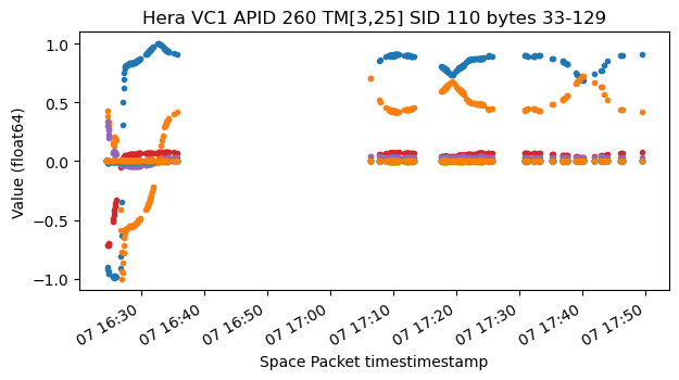
I haven’t been able to identify what any of the telemetry values mean. In particular, there is nothing which looks like attitude quaternions. There is this plot of SID 110 in which the first two variables (orange and blue) have the property that the sum of their squares is always one, but I don’t know how to interpret this.
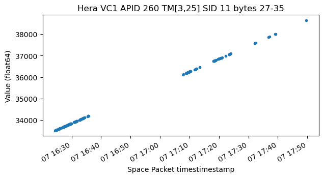
Some of the telemetry fields contain timestamps with respect to the spacecraft clock. They give plots like this one.
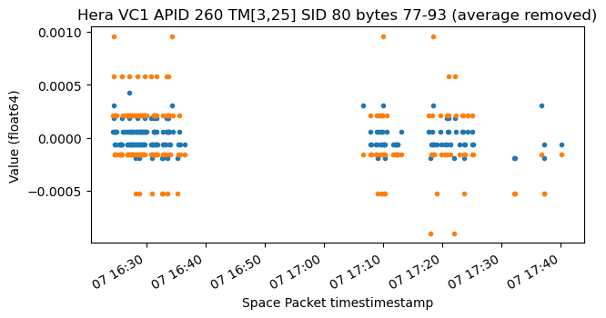
Another thing that is interesting is that despite the fact that these fields are float64, in some of them we can clearly see that the data is quantized in coarser steps (probably because it comes from a measurement with lower resolution). For instance, in this plot the two variables are almost constant.
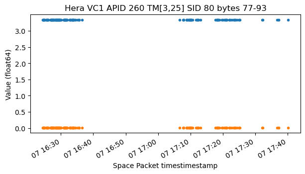
If we subtract its average to each of the variables and plot again, we can see the quantization steps of the data, which are different for the two variables.
APID 263
APID 263 contains packets from the event report service. These are TM[5,1], TM[5,2] and TM[5,3], which are respectively “informative event report”, “low severity anomaly report” and “medium severity anomaly report”.
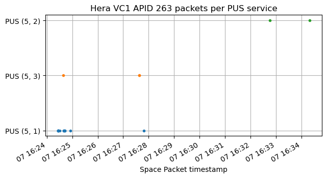
The payloads of these packets are as follows:
['010503bd19a6000000000000000010000000000000000100000000000000000200000082e80a0ea5',
 '010503be19a6000000000000000004000000000000000100000000000000000200000082e80a1016',
 '010503bf19a6000000000000000002000000000000000100000000000000000200000082e80a1155',
 '010503c019a6000000000000000001000000000000000100000000000000010200000082e80a1294',
 '010503e119b7000000000000000300000000000000814b00000000000001000200000082e80a1b2a',
 '01f9000000cd',
 '01fa000000cd',
 '02d7',
 '02cf0203',
 '03e8002d12ef0000000000000000ff000000000000000300000000000000020003000082fb0948dc',
 '03e8003a12ef01ffffffffffffffff000000000000000300000000000000020004000082fb0969a0',
 '0105019f130c0000000000000000ff000000000000000000000000000000000200000082fb09fc3b',
 '010501a0130d0000000000000000ff000000000000000000000000000000000200000082fb09fd9b',
 '010501a1130e0000000000000000ff000000000000000000000000000000000200000082fb09feda',
 '010502e92ddf01ffffffffffffffff000000000000000200000000000000000200000082fb0a5321',
 '02d8',
 '02ce',
 '010501a513190000000000000000ff000000000000000000000000000000000200000083ad0921ff',
 '00050100000000273aa3',
 '00050102000000003209']
According to the PUS standard, the packets begin by an event definition ID, which is probably 2 bytes long, and then there is auxiliary data, whose format depends on the event definition ID and APID. I don’t have enough information to try to interpret the auxiliary data in these reports.
APID 264
APID 264 contains TM[3,26] packets. This corresponds to the diagnostic parameter report in the housekeeping service. It is another form of telemetry variables. As in TM[3,25], the contents of each packet are identified by a SID. In this case, only SID 205 is used. Here is the raster map of this SID.
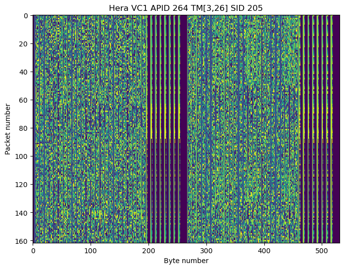
It is apparent that there are many float64 values. The following plot shows all the values in the first half of the packets.
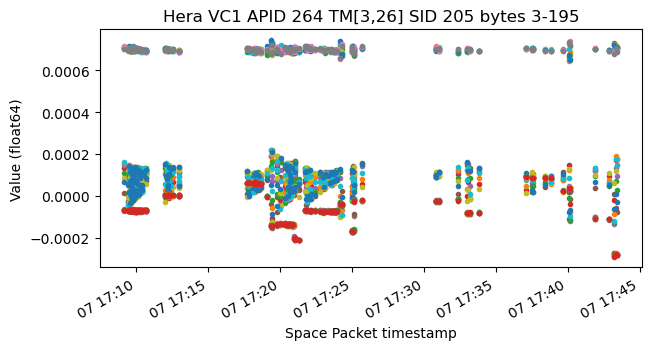
Then there is a section with several timestamps, which probably correspond to different sets of these values.
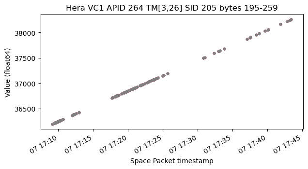
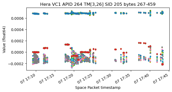
In the second half of the packets there is a similar set of float64 values which give a similar plot.
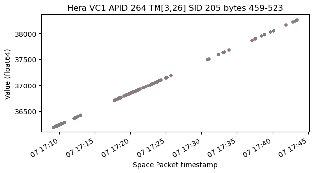
And also the timestamps corresponding to these values.
APID 267
APID 267 contains TM[1,1] and TM[1,7] packets, as well as TM[20,130] packets. This is strange, because TM[20,130] doesn’t appear in the PUS standard, so perhaps it is something custom. There is always a TM[1,1] packet notifying of the telecommand acceptance, then a TM[20,130] packet, and then a TM[1,7] packet notifying of the command execution completion.
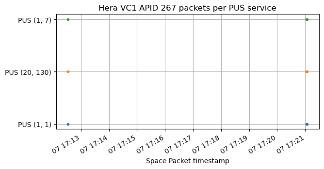
The TM[20,130] packets contains a lot of data, but I don’t know how to parse it.
APID 286
APID 286 contains two TM[1,1] packets. Interestingly, there is no matching TM[1,7] packet for them (perhaps it was lost in the reception).
APID 291
APID 291 only contains one TM[1,1] packet without a matching TM[1,7] packet.
Virtual Channel 3
Virtual channel 3 is used to replay recorded telemetry. Like virtual channel 1, it also contains PUS packets. These are the packets which are transmitted in the virtual channel together with their timestamps. Note that most of the timestamps are before the beginning of my recording. Launch was a 14:52:11 UTC, while the first data from APID 260 has a timestamp of 14:49:03 UTC.
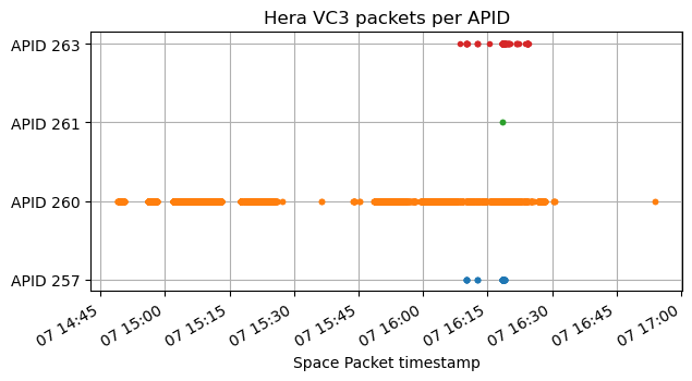
APID 260, which contains the same kind of information as in virtual channel 1, was probably transmitted continuously, so the gaps likely correspond to gaps in my reception.
APID 257
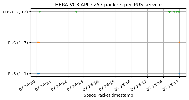
APID 257 contains three pairs of TM[1,1], TM[1,7] packets and 46 TM[12,12] packets. These are check transition report packets from the on-board monitoring service. Spacecraft separation was at 16:07:18 UTC (T+1:16:09), so the first telecommands were executed shortly after separation. They were probably pre-scheduled rather than received in real time over the uplink.
The structure of the payload of TM[12,12] packets is as follows according to the PUS standard.
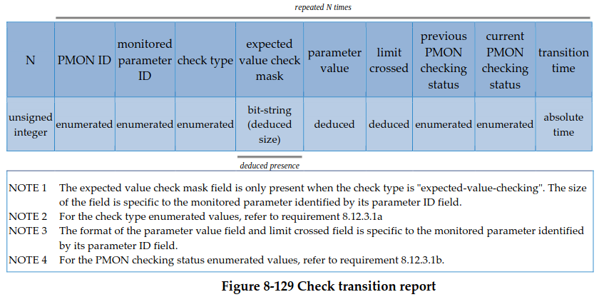
Despite the fact that the standard says that these packets begin with a field N indicating the number of records, the Hera TM[12,12] packets seem to omit this field and contain only one record. The transition time is easy to parse, because it is at the end of the record, and it contains a spacecraft timestamp. It is a 56-bit integer giving \(2^{-24}\) second units.
The check type field is byte 4 (using 0-based indexing) in the payload, so the PMON ID and monitored parameter ID occupy the first 4 bytes. The current PMON checking status and previous PMON checking status are also easy to obtain, because they are one-byte fields preceding the timestamp.
These are the values of these fields in each of the TM[12,12] packets.
check type:
[0, 0, 0, 0, 1, 1, 1, 1, 0, 0, 0, 0, 0, 1, 1, 1, 1, 1, 1, 1, 1, 1,
 1, 1, 1, 1, 1, 0, 0, 0, 0, 0, 1, 0, 0, 0, 0, 0, 0, 0, 0, 1, 1, 0,
 0, 0]

previous PMON checking status:
[2, 2, 2, 2, 2, 2, 2, 2, 2, 2, 2, 2, 2, 0, 0, 3, 3, 2, 2, 2, 2, 2,
 2, 2, 2, 2, 2, 3, 3, 0, 0, 0, 2, 2, 2, 2, 2, 2, 2, 2, 0, 0, 0, 0,
 0, 0]

current PMON checking status:
[0, 0, 0, 0, 0, 0, 0, 0, 0, 0, 0, 0, 0, 4, 4, 0, 0, 0, 0, 0, 0, 0,
 0, 0, 0, 0, 0, 0, 0, 2, 2, 2, 0, 0, 0, 0, 0, 0, 0, 0, 2, 2, 3, 2,
 2, 2]
Check type 0 means expected value checking, while check type 1 means limit checking. The meaning of the checking status is as follows: 0 is expected value or within limits, 1 is unchecked, 2 is invalid, 3 is unexpected value for value checking and below low limit for limit checking, and 4 is above high limit for limit checking.
For the limit checking checks, the parameter value and limit crossed field are float64 fields.
APID 260
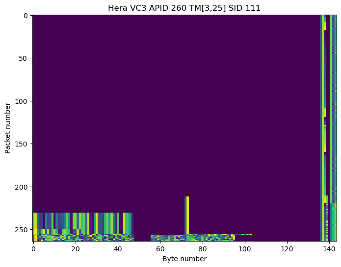
As in virtual channel 1, APID 260 contains TM[3,25] packets which contain telemetry variables. The SIDs are also the same and have the same contents as in virtual channel 1. The main difference is that in some SIDs the valid data only begins at some point, and previously the variables have zeros. This makes sense, because during launch many spacecraft subsystems were probably disabled.
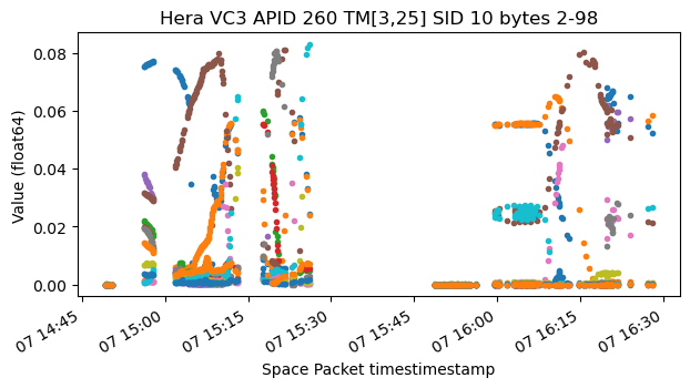
It is interesting to compare some of the plots of the data in virtual channel 3 with the corresponding plots of virtual channel 1. For instance, this plot of some SID 10 variables shows much more dynamic behaviour during the launch.

APID 261
APID 261 contains a single pair of TM[1,1] and TM[1,7] packets.
APID 263
As in virtual channel 1, APID 263 contains packets from the event report service. TM[5,1] is informative event report, TM[5,3] is medium severity anomaly report, and TM[5,4] is high severity anomaly report.
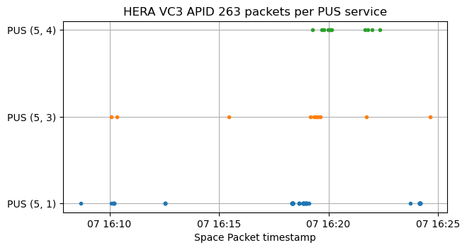
The data of these event reports is similar to that in virtual channel 1. I have noticed that event ID 0105 contains the same data as the TM[12,12] packets in APID 257.
Virtual channel 7
Virtual channel 7 is the idle-only virtual channel. The payload of these frames is filled in the same way as for other ESA missions (which I described in a post about BepiColombo). A 9-bit LFSR is used to generate the contents of the packet zone of the TM frames. The LFSR state is reset to all-ones every 256 frames, when the virtual channel frame count rolls over to zero. In my post about BepiColombo I wondered why this LFSR reset was done. Now that I’ve seen this in several missions, I have realized of a compelling reason. By introducing the reset, the contents of the frame can be generated on ground just from the knowledge of the virtual channel frame count. Therefore, these idle frames become a good way to measure bit error rate, because their contents are random but fully predictable.
CLCW
The Operation Control Field in all the TM frames contains a CLCW (Communications Link Control Word). This CLCW always reports for virtual channel 1. During all my recording, the no bit lock and no RF available flags stay at zero, meaning that a valid uplink signal was always available (or perhaps these flags are not implemented).
Interestingly, during all the 60 kbaud recording the CLCW reports a lockout condition.
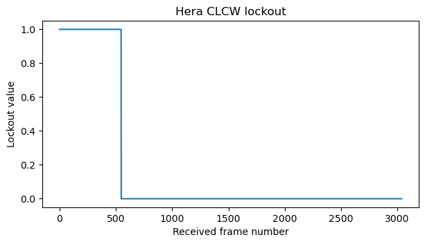
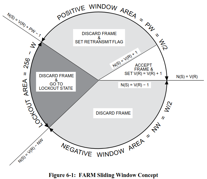
As show by the following diagram taken from the CCSDS COP-1 Blue Book, the lockout state is entered when the FARM (which is the process that checks the sequence numbers of telecommands in order to provide a reliable in-order delivery service called sequence-controlled service) receives a sequence number that is very different from the expected one. This situation needs to be resolved manually by sending an unlock command to the FARM.
The following two plots show the values of the report value and FARM-B counter fields in the CLCW. The report value is the next expected sequence number, so it increments every time that a packet is accepted by the FARM. The FARM-B counter field shows the 2 least significant bits of the FARM-B counter, which counts the number of bypass packets received by the FARM. These are packets which do not use the normal sequence checking and retransmission rules, so they are accepted as soon as they are received (expedited service).
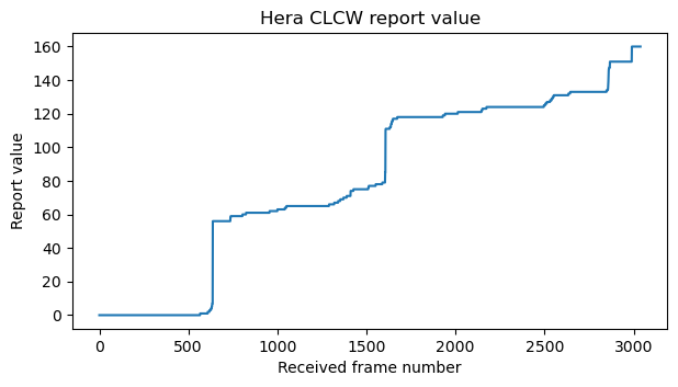
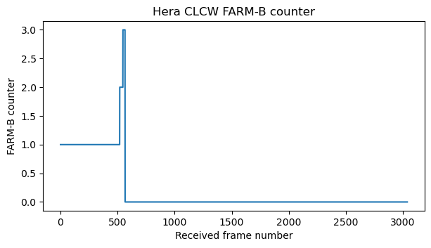
We see that during the 60 kbaud recording the FARM only receives two bypass packets. After the lockout condition is resolved, the report value increments as sequence-controlled telecommands are accepted.
Code and data
The code and data used in this post can be found in this repository. The telemetry analysis was done in this Jupyter notebook.
2 comments