In the previous post, I showed how to use GNU Radio to decode a 3 hour recording of the ESA spacecraft JUICE that I made with the Allen Telecope Array. In this post I will analyse the contents of the telemetry frames.
As I mentioned, the decoder I used was quite slow because the Turbo decoder was rather inefficient. In fact, the 3 hour recording has taken a total of 70.82 hours to process using the gnuradio1 machine at the GR-ATA testbed (a dual-socket Xeon Silver 4216). This means that the decoder runs 23.6 times slower than real time in this machine. Here I have used the decoder that beamforms two ATA antennas, as I described in the previous post. In total, 152 MiB worth of frames have been decoded.
TM frames
The frames are CCSDS TM Space Data Link frames. The spacecraft ID contained in the frames is 0x34c. This ID is registered to the JUICE X-band return link in the SANA registry. The other links registered for JUICE (the Ka-band return link and the X-band forward link) also use spacecraft ID 0x34c.
All the frames have a secondary header. The secondary header contains a 3-byte data field that extends the 8-bit virtual channel frame count field in the primary header to a 32-bit counter. This is quite useful to keep track of how many frames are lost, since an 8-bit counter rolls over too quickly.
Virtual channels 0, 1, 4 and 7 are in use in this recording. As usual, virtual channel 7 is the OID (only idle data) virtual channel.
With the help of the virtual channel frame count field, I have been able to determine how many rollovers happen in the master channel frame count field (which is only 8-bits wide) when there are gaps in the reception, and obtained a correctly unwrapped version of the master channel frame count. This can be used to compute how many frames have been lost, and also to give approximate timestamps to the frames, assuming a nominal frame duration of about 68 milliseconds, and that the first frame was decoded at the beginning of the recording. This gives the following plot of frame loss over time, which uses a logarithmic scale.
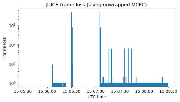
It is good to compare this with the waterfall of the recording from the previous post, shown again here for convenience. When the medium-gain or high-gain antennas are used, no frames are lost, since the signal has more than enough SNR to be decoded. When the low-gain antenna is used, there is some frame loss. This is approximately 0.36% around 06:15, and 1.2% between around 07:15 and the end of the recording. Perhaps it could be possible to optimize the decoder somewhat more and bring the frame loss down to zero, but this is already good enough for my purposes.
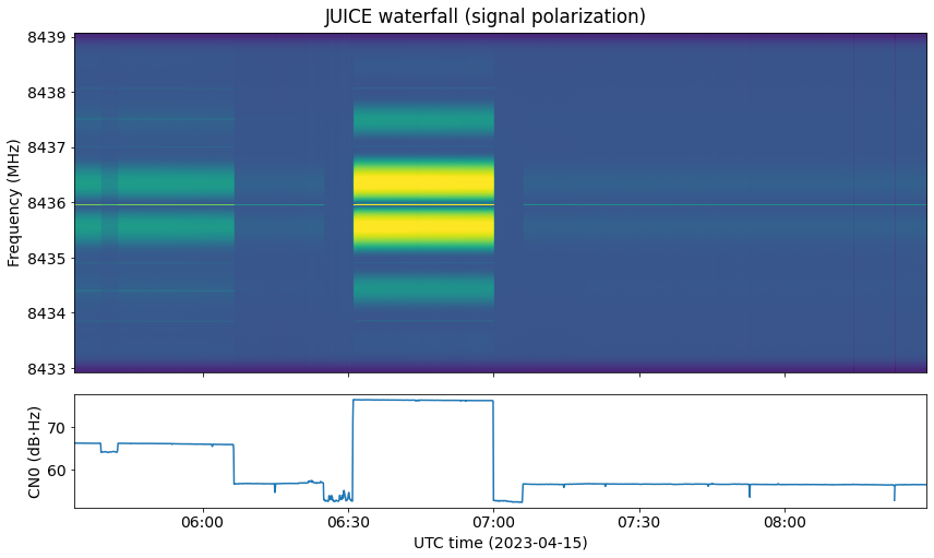
Note that there are two gaps in which there is no signal from the spacecraft. These cause the frame loss spikes which indicate that several thousands of frames are lost.
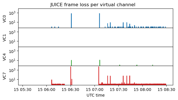
Here is the frame loss per virtual channel. This can be computed directly using the extended 32-bit virtual channel counter.
The following two figures illustrate the virtual channel usage. The first figure shows when frames are transmitted in each virtual channel. The second figure shows the relative usage measured over 100 second intervals.
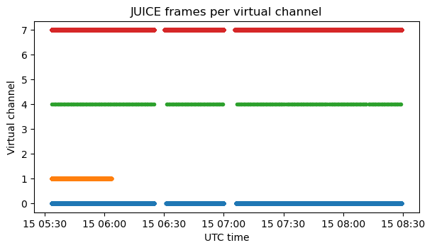
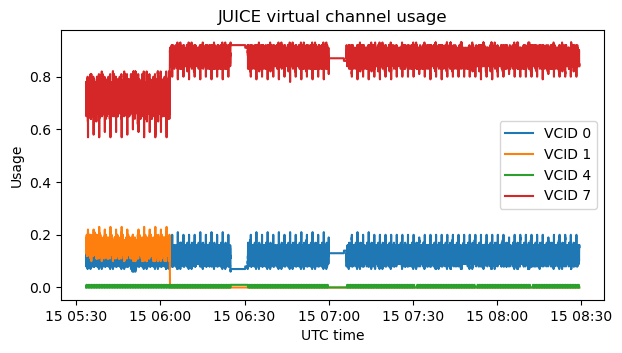
We can see that the link occupation is low. Between 70 and 85% of the link usage corresponds to the idle virtual channel. At the beginning of the recording, VC1 is active, but then it stops completely. VC4 is active throughout all the recording, but it uses very little bandwidth.
All the frames have an OCF (Operation Control Field), which contains a CLCW (Communications Link Control Word). These are analysed in a section at the end of the post.
Virtual channel 0
Frames from virtual channel 0 contain CCSDS Space Packets. There are many APIDs in use. Most of the APIDs use PUS (the ECSS Packet Utilization Standard). The version of PUS that is used is version 1, which is described in ECSS-E-70-41A (from 2003). Note that there is a more recent PUS version 2 described in ECSS-E-ST-70-41C15 (from 2016).
This figure shows the contents of the PUS data field header in PUS version 1. This header is the secondary header of the CCSDS Space Packets.
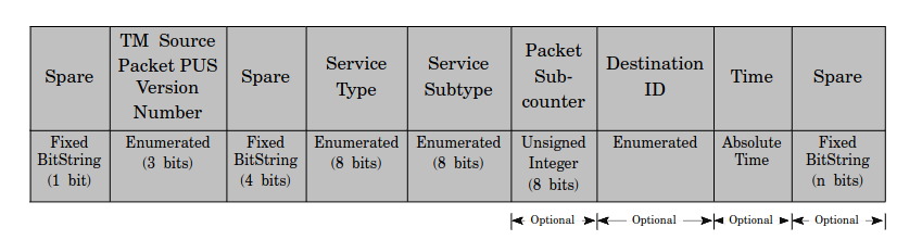
In the case of JUICE, the packet sub-counter field is not present. There is an 8-bit field following the service subtype field. This could be the destination ID field, or the most-significant bits of the time field. Besides potentially these 8 bits, the time field contains 48 bits which give the timestamp as the number of \(2^{-16}\) second units since the J2000 epoch (2000-01-01 00:00:00).
All the APIDs use PUS except for APID 0 and APID 2047 (the idle APID). APID 0 packets do not have a secondary header. However, the packet payload begins by the bytes 0x052f and then contains a 48-bit timestamp in the same format as the PUS packets. APID 2047 packets do not have a secondary header either. There are no timestamps in APID 2047 packets.
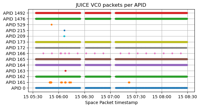
The figure below shows when packets are transmitted in each APID. Several of the APIDs have traffic continuously, but others only send packets sparingly.
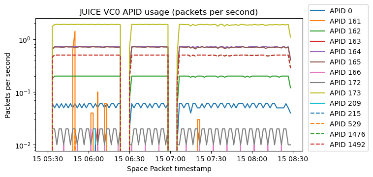
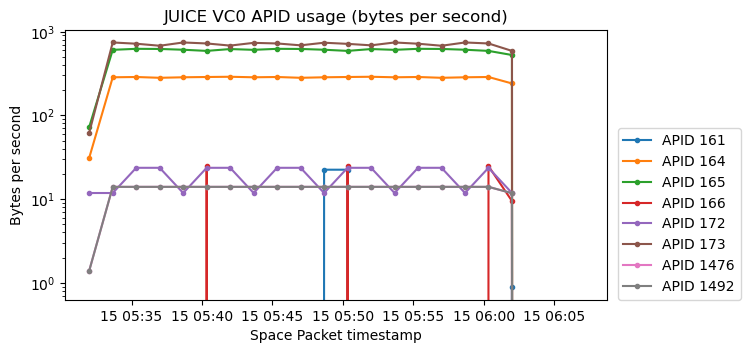
A different view at the APID usage is given by the two next figures, which show the number of packets per second and bytes per second transmitted in each APID, measured in averages of 100 seconds.

The Space Packets in each APID except for APID 2047 have a CRC-16 as Packet Error Control Field. The CRC is the one specified in Appendix A.1 of ECSS-E-70-41A.
Next we describe the contents of each APID in virtual channel 0.
APID 0
APID 0 is unusual because it doesn’t consist of PUS packets. The payload of the Space Packets has 11 bytes. The first two bytes are always 0x052f. The next 6 bytes are a 48-bit timestamp as described above. The last 2 bytes are the CRC-16. This only leaves one byte of actual data. The value of this byte in each APID 0 packet is plotted below. I have no idea of what this data is.
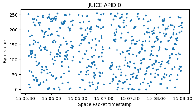
Update 2023-05-03: Luna mentions on Twitter that APID 0 is reserved in PUS for time reports, and explains how these packets should be parsed. Indeed, ECSS-E-70-41A Section 4.2.1 says that “APID=0 shall be reserved for the standard spacecraft time packet”, and Appendix C.3 describes the format of spacecraft time source packets. According to this, the byte 0x05 indicates the rate at which time packets are sampled, and corresponds to a value of 32 frames. The byte 0x2f is the timecode P-field, and indicates that the timestamp (T-field) has 7 bytes and uses units of \(2^{-24}\) seconds. Therefore, the byte I have plotted above corresponds to the 8 LSBs of the timestamp. These time packets are interesting because their timestamp is sampled in a precisely defined location of the telemetry stream, as defined by Appendix C.4 (at the leading edge of the ASM of some of the frames in virtual channel 0).
APID 161
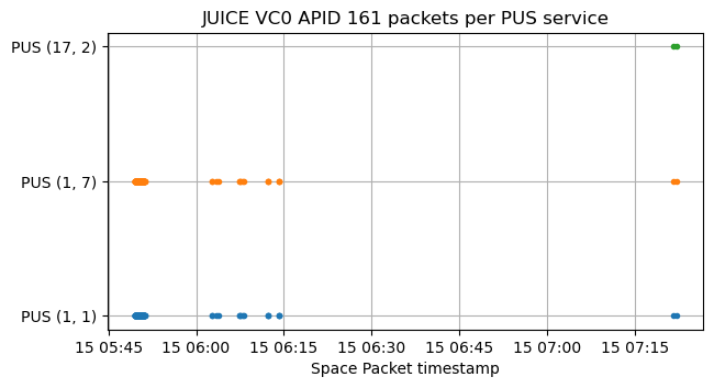
APID 161 contains PUS packets with the following service types and subtypes:
- (1, 1). Telecommand Acceptance Report – Success (Telecommand verification service).
- (1, 7). Telecommand Execution Completed Report – Success (Telecommand verification service).
- (17, 2). Link Connection Report (Test service).
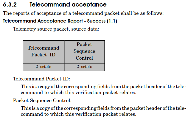
The telecommand verification service is, as its name suggests, used to report successful or failed acceptance and completion of telecommands received by the spacecraft. The following shows the contents of Telecommand Acceptance Report – Success packets. The contents of Telecommand Execution Completed Report – Success packets are identical. These 4 bytes are, indeed, the first 4 bytes of the Space Packet corresponding to the telecommand, which are the Space Packet Primary Header minus the packet data length field.
The Link Connection Report packets play a role similar to ICMP ping replies in IP networks, and have no payload.
This plot shows when each PUS packet is transmitted. The PUS (1,1) and PUS (1,7) packets come in pairs. There is first a PUS (1,1) packet indicating reception of the telecommand, and some milliseconds later a PUS (1,7) packet indicating completion of the telecommand (these include matching Space Packet headers in their payloads). There are only two PUS (17,2) packets.
The Space Packet headers contained in the payloads of the Telecommand verification service packets look like this (I have set the data length field to zero manually because it is not included in the payload):
Container(ccsds_version=0, packet_type=1,
secondary_header_flag=True, APID=172,
sequence_flags=3, packet_sequence_count_or_name=2717,
data_length=0)
Note that the packet type is 1, which indicates telecommand. All the packets belong to APID 172, and their packet sequence count increases by one each time.
APID 162
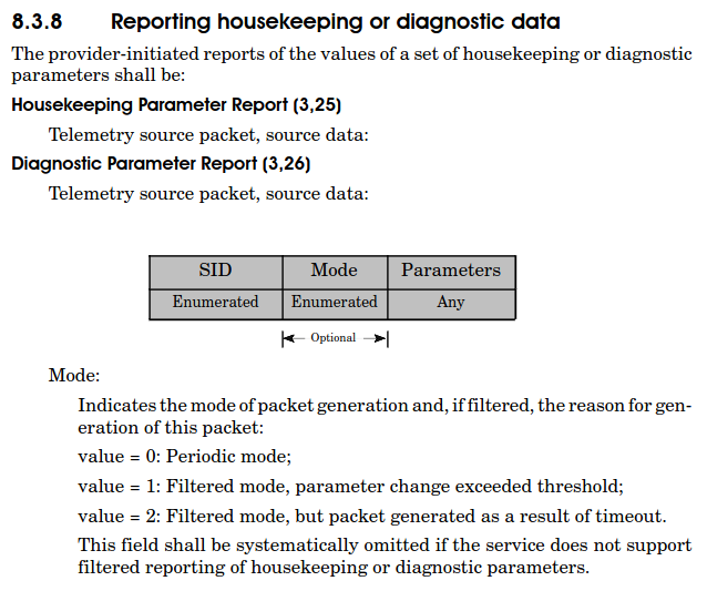
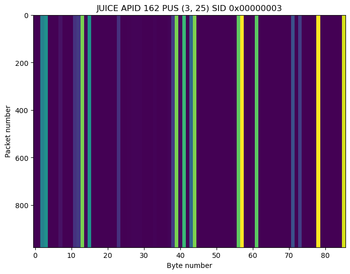
APID 162 contains PUS packets using service type and subtype (3, 25). This corresponds to Housekeeping Parameter Reports (Housekeeping and diagnostic data reporting service). This is the way in which PUS sends telemetry values sampled at regular times by the spacecraft, so we will see PUS (3, 25) packets in other APIDs as well.
The following shows the format of the payload of PUS (3, 25) packets. There is a SID (service ID), which in the case of JUICE has 4 bytes. Together with the APID, the SID identifies the type of the telemetry message. The mode field is not present in JUICE. Finally, the parameters are free format, and depend on the SID and APID.
APID 162 contains packets from SIDs 0x00000002 and 0x00000003 (more or less in the same amount). Throughout the recording, these contain static values, and mostly zeros, as shown in these raster maps.

APID 163
APID 163 contains PUS packets using service type and subtype (156, 2). This is supposed to be a mission defined service type. There are only two packets sent in this APID, and they mostly contain zeros.
APID 164
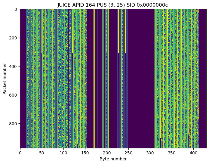
APID 164 contains PUS (3, 25) packets from 12 different SIDs ranging between 0x0000000f and 0x00000046. The following shows the raster map of one of the SIDs as an example. The Jupyter notebook contains plots for all the SIDs.
APID 165
APID 165 is similar to APID 164. It contains PUS (3, 25) packets from 17 SIDs ranging between 0x00000047 and 0x00000059. Plots for these are contained in the Jupyter notebook.
APID 166
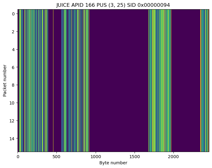
APID 166 is sent sparingly and contains PUS (3, 25) packets from SIDs 0x00000087 (only 2 packets) and 0x00000094 (16 packets). These contain mostly static data.

APID 172
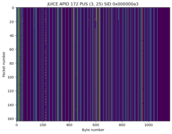
APID 172 contains PUS (3, 25) packets from SID 0x000000a3. The payload of these packets contain some short ASCII strings such as COMS, BUS1, BUS2, CHA and CHB.
APID 173
APID 173 contains PUS (3, 25) packets from 10 SIDs ranging from 0x000000ab to 0x000000bd. Raster maps for these are included in the Jupyter notebook.
APID 209
In the recording, APID 209 only contains two packets, one from PUS (1, 1) (telecommand successful acceptance) and the corresponding PUS (1, 7) (telecommand successful completion). The corresponding telecommand Space Packet header is the following:
Container(ccsds_version=0, packet_type=1,
secondary_header_flag=True, APID=220,
sequence_flags=3, packet_sequence_count_or_name=1142,
data_length=0)
The timestamps of the PUS (1, 1) and PUS (1, 7) packets are the following:
2023-04-15T06:06:23.879959168
2023-04-15T06:06:27.630004864
APID 215
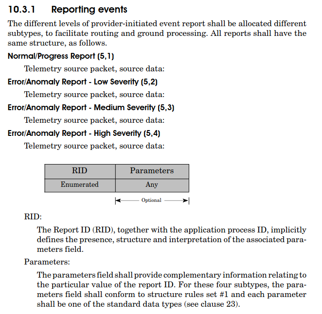
APID 215 contains a single packet from PUS (5, 1). This is a Normal/Progress Report (Event reporting service). The format of the payload of event reports is given here. The payload is divided in a RID (report ID), and free-form parameters.
The payload of this packet is hex is 0x000025c006. Perhaps this is divided into the RID 0x000025c0 and the parameters 0x06, or the RID 0x000025 and the parameters 0xc006.
APID 529
As in the case of APID 209, APID 529 contains a single PUS (1, 1) and its corresponding PUS (1, 7) packet. The telecommand Space Packet header is
Container(ccsds_version=0, packet_type=1,
secondary_header_flag=True, APID=540, sequence_flags=3,
packet_sequence_count_or_name=14663, data_length=0)
The timestamps of acceptance and completion are
2023-04-15T05:51:34.387969920
2023-04-15T05:51:34.388717696
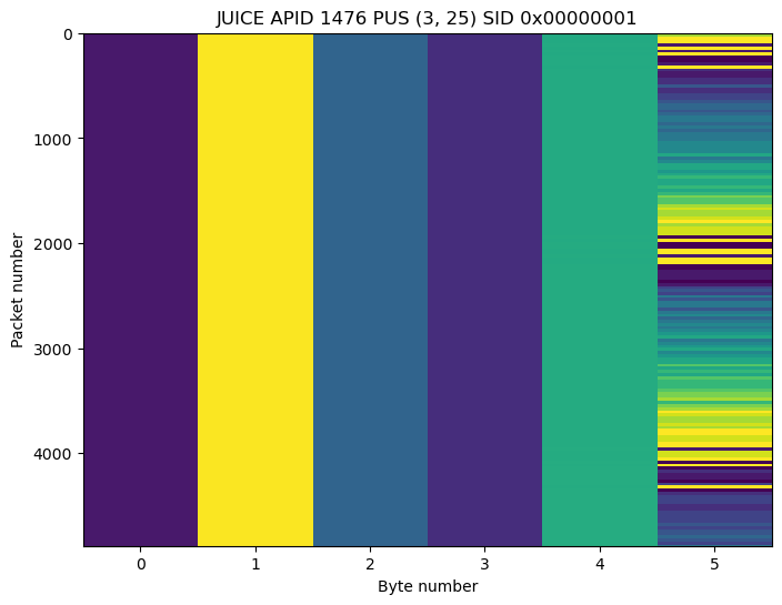
APID 1476
APID 1476 contains PUS (3, 25) packets from SID 0x00000001. A raster map is shown here. Only the last byte of the payload changes.
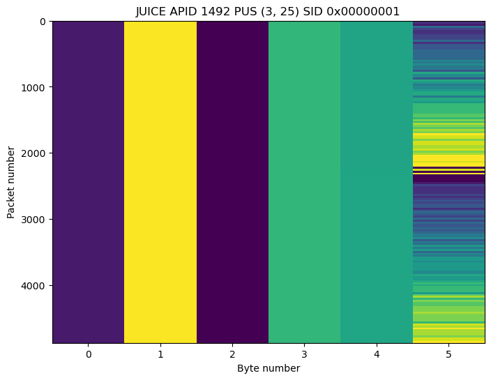
APID 1492
APID 1492 contains PUS (3, 25) packets from SID 0x00000001. This is the same SID as in APID 1476. The format of the packets seems to be the same, but the contents are different.
APID 2047
APID 2047 is used, as defined by CCSDS, to send idle packets. These packets have always 8 bytes of payload, and the packet sequence count field in the header is set to zero. The contents of the payload seem pseudo-random, but I don’t know what algorithm is used to generate them. Interestingly, it seems that the value 0x00 is half as likely to occur in the payload as any of the other values, which are more or less equally likely. The following is a raster map of all the received idle packets.

These idle packets are used to “flush” the payload of a TM Space Data Link frame. When there are no more Space Packets to fill up the current frame, the remaining space is filled with idle packets so that the frame can be sent immediately.
This happens, for example, in the second VC0 frame decoded from the recording. At the beginning of the payload there is the end of a packet (the first header pointer is 217). Then there is a packet from APID 165, a packet from APID 173, and several APID 2047 idle packets to fill up the frame.
Virtual channel 1
Virtual channel 1 is only active until 06:03:24 UTC. Interestingly, it re-sends in real-time a selection of the APIDs in virtual channel 0. This capability does not seem too useful (we get exactly the same frames twice at almost the same time), so perhaps in general this virtual channel can be used to send pre-recorded data instead of real-time data.
This shows the APIDs transmitted in virtual channel 1 (there is also the idle APID 2047, which has idle packets just like those in virtual channel 1).

Here is the usage of each APID, measured both in packets per second and bytes per second, using 100 second averages.
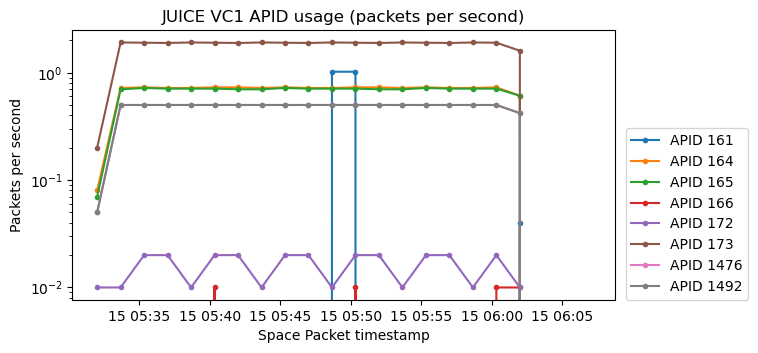
The packets transmitted in each APID are exactly the same (timestamps included) as the first packets received in each of the corresponding APID of virtual channel 0 (ignoring the very first packet in some of the APIDs in virtual channel 0). This clearly shows that virtual channel 1 is transmitting a subset of the data in virtual channel 0.
Virtual channel 4
Virtual channel 4 contains Space Packets of a single APID: APID 148 (as well as idle packets from APID 2047). The packets in this APID have fixed size and do not have a secondary header. The next figure shows a raster map of these Space Packets. They are clearly divided in two similar sections.
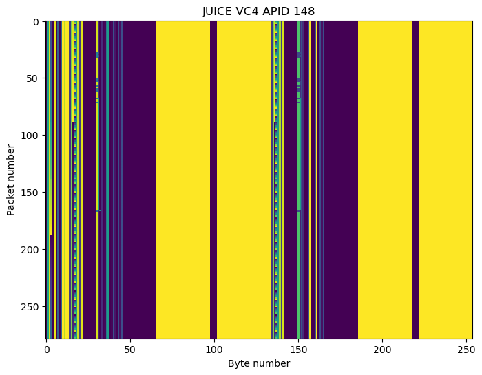
At the beginning of each of the two sections, there is a 32-bit timestamp that gives the number of seconds since the J2000 epoch (2000-01-01 00:00:00). The timestamps in each of the two sections of a packet have the same value. According to the timestamps, one of these packets is sent every 34 or 35 seconds. The remaining space in the TM frame is filled with APID 2047 idle packets.
Virtual channel 7
Virtual channel 7 is the only idle data virtual channel. Here is a raster map of the frames in this virtual channel.
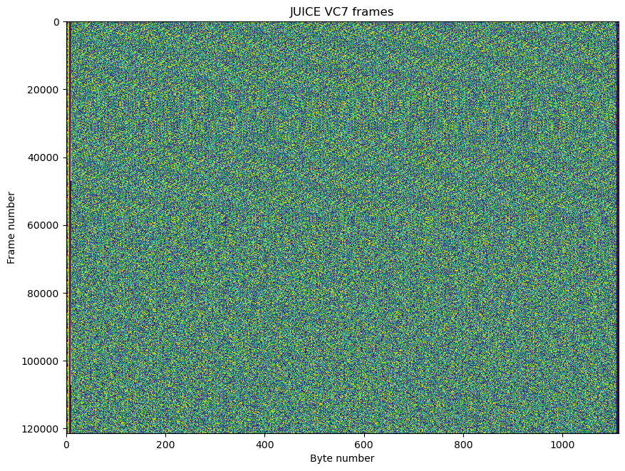
The payload in these frames obeys exactly the same description as the idle frames of BepiColombo. The payload is generated using a PN9 sequence, but the sequence is reset every time that the virtual channel frame count rolls back to zero.
The following Python code can be used to generate the payload of an idle frame, given its 8-bit virtual channel frame count.
lfsr = np.ones(9, dtype = 'uint8')
lfsr_out = np.empty(511, dtype = 'uint8')
for j in range(lfsr_out.size):
    out = lfsr[8] ^ lfsr[4]
    lfsr_out[j] = lfsr[8]
    lfsr = np.roll(lfsr, 1)
    lfsr[0] = out

def gen_idle_payload(vcfc):
    start = (8792 * vcfc) % 511
    lfsr_out_repeat = np.tile(
        lfsr_out, int(np.ceil(8792 / 511)) + 2)
    return bytes(np.packbits(
        lfsr_out_repeat[start:start+8792]))
CLCWs
The OCF (operational control field) of the TM Frames contains a CLCW (communications link control word). CLCWs report information about the state of the uplink and the COP-1 protocol used to deliver telecommand frames from ground. The structure of a CLCW is given in the TC Space Data Link Protocol Blue Book and reproduced here.
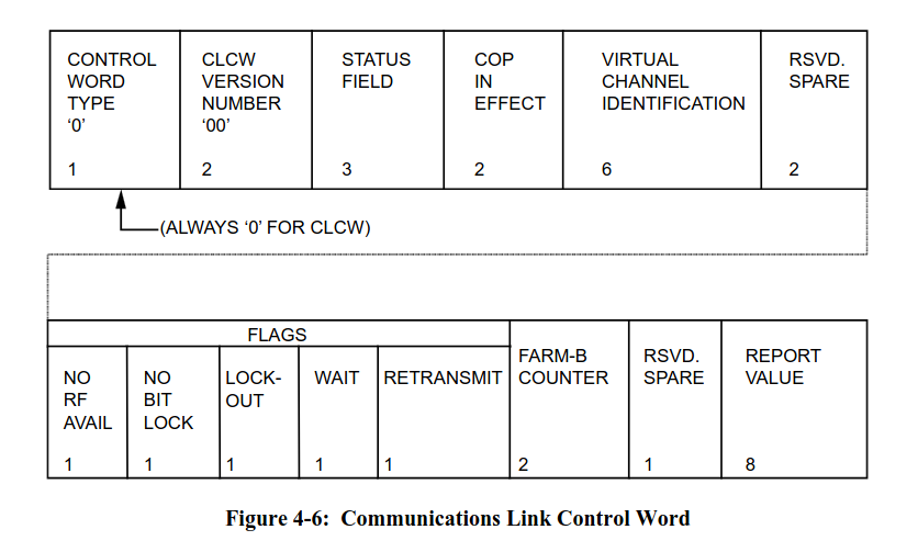
In the case of JUICE, CLCWs report information about two (telecommand) virtual channels: virtual channel 1 and virtual channel 2. The reporting alternates every other TM Frame, in such a way that TM Frames with an even master channel frame count contain a CLCW for virtual channel 1, and TM Frames with an odd master channel frame count contain a CLCW for virtual channel 2.
The status, lock-out, wait, and retransmit fields are always set to zero throughout the recording. The following shows a plot of the no RF available and no bit lock flags. We see that no bit lock is asserted every time that no RF available is asserted (as expected), but sometimes no RF available is not asserted while no bit lock is asserted (and actually no RF available oscillates in some moments around the changes of no bit lock).
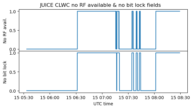
It is interesting that these flags suggest that an uplink carrier was not present during a large part of the recording. In particular, the test of the high-gain antenna between 06:30 and 07:00 seems to have been done without an uplink carrier lock.
The following plot shows the report value field. This field contains the sequence number of the next telecommand frame that the FARM sequence-controlled service expects to receive. Generally, it increases by one every time that a sequence-controlled (Type-AD) telecommand frame is successfully received.
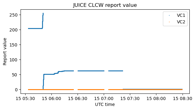
For virtual channel 2 the report value always stays at zero, but for virtual channel 1 the report value increases many times. Most of these roughly coincide with the moments in which the PUS (1, 1) service in APID 161 is reporting successful reception of telecommand packets, so we see that these packets are sent in virtual channel 1 (the plot of the packets in APID 161 is repeated here for convenience).
At 07:21:28 the report value suddenly resets to 1. Then it increases to 2 at 07:22:10, staying there until the end of the recording.

The next plot shows the value of the FARM-B counter field. This is a 2-bit counter that increments every time that an expedited (Type-B) telecommand frame is successfully received.

The FARM-B counter for virtual channel 2 always stays at 2 throughout the recording. The FARM-B counter for virtual channel 1 starts at 1, then increases to 2 at 07:21:28 and then increases to 3 at 07:21:39. The increase to 2 happens approximately 130 ms before the report value for virtual channel 1 gets reset to 1. Therefore, it appears that the expedited frame received at 07:21:28 was a “Set V(R)” directive, which is used to set the V(R) counter of the FARM and resynchronize the COP-1.
Code and data
The decoded frames can be found in this Zenodo dataset. The analysis and plots have been done in this Jupyter notebook.
One comment