Lunar Flashlight is a 6U NASA cubesat whose mission is to detect the presence of water ice on permanently shadowed regions of the lunar south pole. It was launched on December 11 2022 together with Hakuto-R M1 (to which I dedicated my previous post). It travels using a low-energy transfer to lunar orbit, so it will arrive to the Moon in a few months.
The day after the launch, AMSAT-DL made an IQ recording of the X-band beacon of Lunar Flashlight at 8457.27 MHz with the 20 metre antenna at Bochum observatory. The recording was done on 2022-12-12 17:08:54 UTC and lasts 3 minutes 2 seconds. In this post I will analyse the recording.
Modulation and coding
The modulation used by Lunar Flashlight is PCM/PM/bi-phase-L. This means that the telemetry is Manchester encoded and phase modulated with a residual carrier. The nominal baudrate is probably 48 kbaud. To be more precise, I have measured 48077 baud. Coding is r=1/6 CCSDS Turbo code with 8920 bit frames. This is the CCSDS coding that provides the best Eb/N0 performance.
The figure below shows the GNU Radio flowgraph that I have used to decode this recording. The flowgraph uses the Turbo decoder block from gr-dslwp and some blocks from gr-satellites.
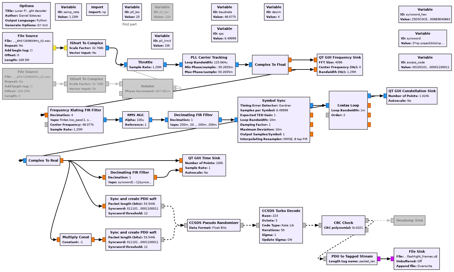
At some point in the recording, there is a frequency jump of approximately 121 kHz. This is probably caused by the spacecraft locking or unlocking to an uplink carrier from the groundstation. The recording is therefore processed in two segments, using different File Source blocks for each of the segments. In the second segment there is actually a second, much smaller, frequency jump. For this reason, the PLL bandwidth for the second segment is set to 100 Hz, so that the jump can be tracked correctly. For the first segment, a PLL bandwidth of 25 Hz is used, which gives less jitter.
The figure below shows the GUI of the decoder flowgraph. The top left plot is the spectrum at the output of the PLL, showing the real and imaginary parts separately. I don’t know why there is a significant amount of modulation power on the real part (besides the residual carrier). This only happens at the beginning of the recording. A few seconds before the frequency jump the power in the real part disappears. It briefly appears again for a few seconds some time after the frequency jump.
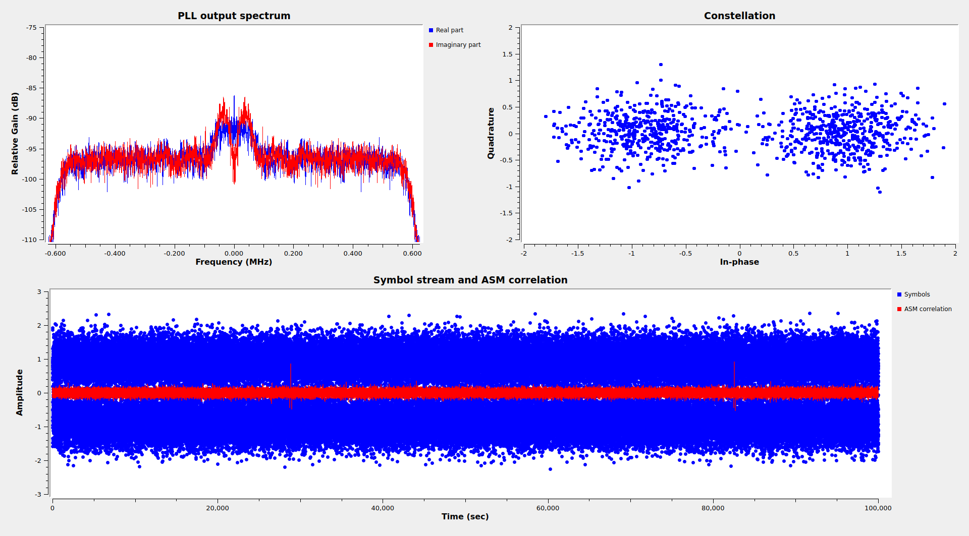
The top right plot shows the constellation plot. We see that the SNR is good and there are few bit errors. The bottom plot shows a time domain plot of the stream of symbols and the correlations with the 192-bit ASM.
AOS frames
Lunar Flashligh transmits CCSDS AOS Space Data Link frames using spacecraft ID 0x81. This ID is assigned to the return link of Lunar-Flashlight in SANA registry. The forward link has assigned a different spacecraft ID, 0x36B. We have seen this tendency to use different spacecraft IDs for the forward and return links in most of the cubesats that have been launched to the Moon on the end of 2022.
Only virtual channel 2 is in use. There is no Operational Control Field or AOS Insert Zone, but there is a Frame Error Control Field (CRC-16), as recommended for Turbo coded frames. The GNU Radio flowgraph checks this CRC-16. In this recording, only one frame was lost, due to the frequency jump happening mid-frame.
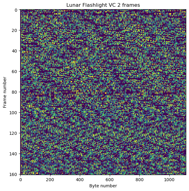
The figure below shows a raster map of all the AOS frames. No structure is immediately recognizable.
The frames contain CCSDS Space Packets using the M_PDU protocol. The Space Packets belong to several APIDs and have different sizes. Typically all the packets from the same APID have the same size, but APIDs 1 and 98 that are an exception to this. All the packets have the secondary header flag asserted.
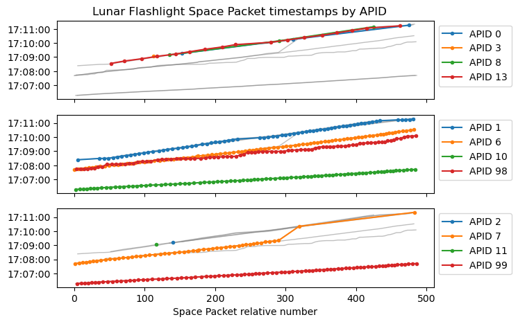
I have determined that the secondary header contains a 48-bit timestamp that indicates the number of \(2^{-16}\) second ticks elapsed since the J2000 epoch 2000-01-01 12:00:00. Interestingly, the packets in each APID are sent with timestamps that differ by up to a couple of minutes, as if some APIDs were buffered or delayed or used a different time source.
The plots below try to illustrate this. The APIDs are separated in three plots only to make the plots less busy. In each plot, thin grey lines are shown in the background for all the APIDs for easier reference. In the foreground, four coloured lines for four APIDs are shown. The x-axis represents the Space Packet relative number, which corresponds to the order in which the Space Packets have been received. Since the recording starts at 17:08:54 UTC, I would say that the APIDs 0, 1, 2, 3, 8,11, and 13 are sent close to real time, and the other APIDs are delayed by one or two minutes. APID 7 is specially interesting because its delay changes at some point.
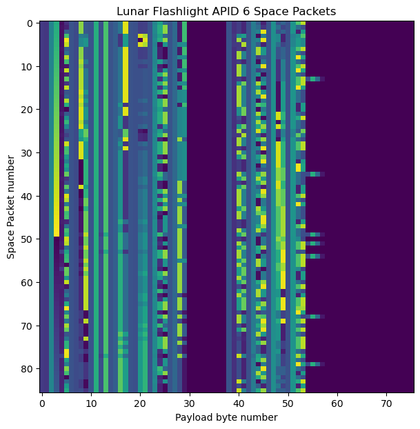
APID 6 probably contains some kind of real-time telemetry, judging by the fact that it is sent regularly and by the looks of its raster map, shown here.
The Jupyter notebook contains raster maps of all the APIDs.
APID 1 is specially interesting. It contains Space Packets of four different lengths: 33, 94, 1021, and 2041 (these are the values of the Space Packet data length fields). The packets of different lengths are sent in a regular sequence, as we can see in the raster map. Shorter frames have been padded with zeros at the end, which are shown as a purple colour. First there is a length 33 packet and a length 94 packet. Then there are a bunch of length 2041 packets. Finally there is a length 1021 packet, and the sequence repeats again.
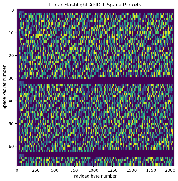
Even though it is not easy to see the structure of the data in this raster map, we can see a diagonal pattern. It turns out that in the packets of length 2041, the segment from byte 28 of the payload to 6 bytes before the end of the packet contains a concatenation of Space Packets of length 165 bytes. Since 165 does not divide the size of this segment, the packets that become fragmented at the end of a packet continue in the next packet. Similarly, the packets of length 1021 also contain Space Packets starting at byte 28.
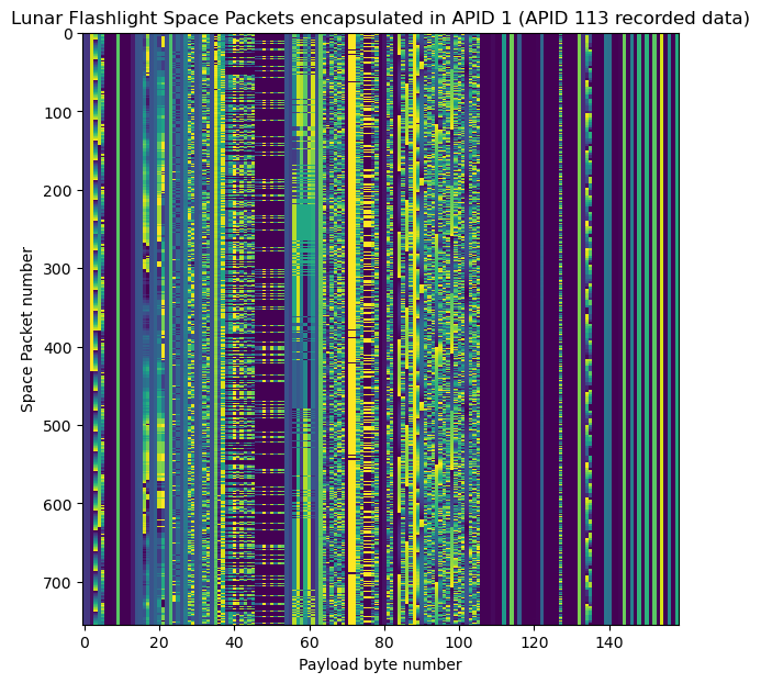
All of the Space Packets that are encapsulated in APID 1 belong to APID 113. Looking at the timestamps of these encapsulated packets, we see that they correspond to pre-recorded telemetry which is being replayed. The timestamps are spaced approximately 10 seconds apart, and in this recording they cover from 7:40:29 to 9:48:22. This is probably a time interval during which the spacecraft wasn’t being tracked by any grounstation, so now that a groundstation is tracking, all the recorded data is downlinked on demand.
The next figure shows the raster map of these packets. As we will see in the next section, they contain telemetry for the ADCS, and probably other subsystems.
It is interesting that the total length of the packets with data length field 2041 (once we take into account the size of the Space Packet Primary Header) is 2048 bytes. This suggest that this is the maximum Space Packet size for this spacecraft, so when replayed telemetry packets are being sent, they are encapsulated in Space Packets that are as large as possible. Each transfer comes preceded by some kind of announcement, which are the two shorter packets. Since the transfer doesn’t fill up an integer number of length 2041 packets, the last packet is shorter, which explains the length 1021 packets.
Although the only clue that we have in this data is the fact that virtual channel 2 is used, we know that Lunar Flashlight uses the IRIS radio, because it is mentioned in this paper. We have been seeing in the last series of posts that most of the cubesats that have been launched to the Moon use this radio, which has a number of distinguishing features, including using virtual channel 2 for the telemetry and 0xdc as a filler byte for only idle data and idle packets.
ADCS telemetry
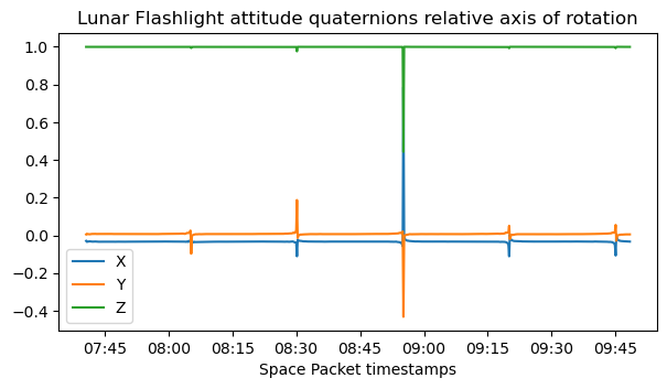
The APID 113 packets encapsulated in APID 1 contain ADCS telemetry. The techniques we will follow in this analysis are very similar to those I used for Hakuto-R M1. Bytes 90 to 106 in these packets interpreted as big-endian int32 contain the attitude quaternions. These are in scalar-last format, and use a scale factor of \(2\cdot 10^9\). As we will see, they encode the rotation from the spacecraft body frame to ICRF (or a similar system, such as equatorial J2000). Thanks to the fact that APID 1 replays pre-recorded telemetry, we can see the evolution of the attitude over the course of two hours.
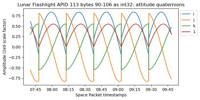
The jumps that we can see in the quaternion data correspond to a change of sign in the \(i, j, k\) components with the goal of making the scalar component always positive. We have also seen this behaviour in other spacecraft.
The next figure shows the relative axis of rotation in spacecraft body coordinates. This has been computed as the axis of rotation of \(q(t)^{-1}q(t_0)\), where \(q(t)\) are the spacecraft body to ICRF quaternions shown above, and \(t_0\) is the first timestamp in the data. We see that the axis of rotation is constant and close to the spacecraft Z-axis.
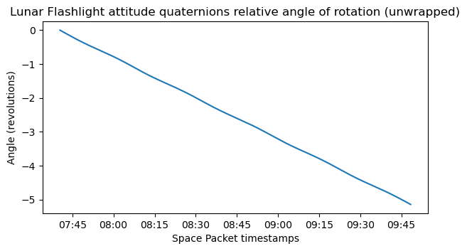
Next we plot the relative rotation angle. This has been unwrapped, since over the course of two hours the spacecraft completes 5 revolutions. The rotation angle changes almost as a linear slope, which means that the rotation rate is almost constant.
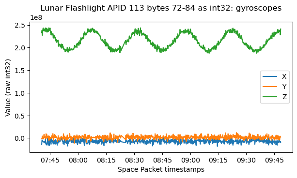
Bytes 72 to 84 contain the gyroscope angular velocity as big-endian int32. This agrees with the quaternion data, since the rotation happens mostly in the Z-axis and its angular speed is roughly constant, but oscillates in a sinusoidal fashion.
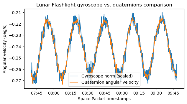
We can compute the norm of the gyroscope vector, which indicates the total angular speed, and try to match it with the time derivative of the rotation angle computed with the quaternions. This helps us check the consistency of the data and find the scale factor for the gyroscopes. The plot below shows good agreement, and uses a gyroscope scale factor of \(-1.118\cdot 10^{-9}\). I haven’t been able to explain this scale factor in terms of a nice number and an appropriate choice of units (rad, deg, rpm, etc.).
There are some other telemetry fields that show sinusoids which are probably related to the ADCS. I haven’t been able to find the meaning of these fields. Their plots are shown in the Jupyter notebook.
We have seen that the spacecraft is rotating slowly about its Z-axis, at a rate of approximately 2.5 revolutions per hour. This seems to be a deliberate spin stabilization configuration. Below we can see an image of Lunar Flashlight. We see that all the solar panels point in one direction. Therefore, it is quite likely that this direction is along the Z-axis, and the spacecraft is slowly rotating around the Z-axis while keeping its solar panels pointed to the Sun.
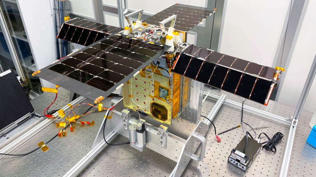
I have taken from NASA HORIZONS the spacecraft’s position in heliocentric ICRF coordinates at 07:30 TDB and used that to compute the Sun vector from the point of view of the spacecraft. Note that we can assume the Sun vector to be almost constant during the 2 hours of data we have. The figure below shows the ICRF coordinates of the Z-axis of Lunar Flashlight and of the Sun vector. We see that the Z-axis oscillates, since the spacecraft’s rotation axis is not perfectly aligned with the Z-axis. However, this oscillation is well centred on the Sun vector. This confirms our idea the the spacecraft Z-axis is orthogonal to the plane where the solar panels lie and that the Solar panels are being pointed directly to the Sun.
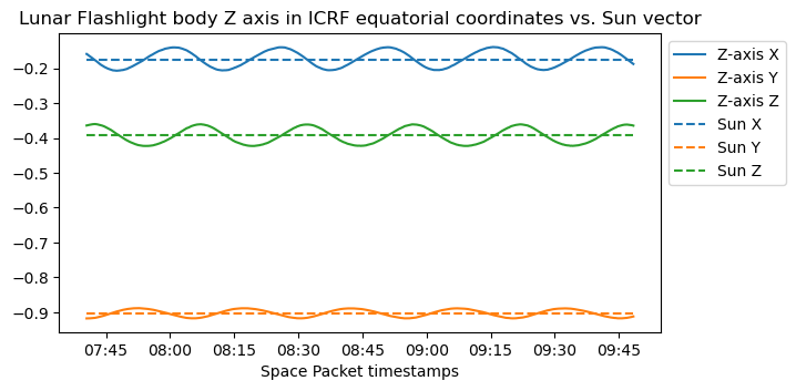
In fact, the paper Systems Integration and Test of the Lunar Flashlight Spacecraft confirms our understanding of the spacecraft body axes definition, since it includes the figure reproduced here.

Our next question is what happens with the spacecraft antennas. The paper indicates that:
Lunar Flashlight has two pairs of planar patch antennas, one on the propulsion system (+Z) side and one on the payload radiator (−Z) side.
Systems Integration and Test of the Lunar Flashlight Spacecraft, page 11
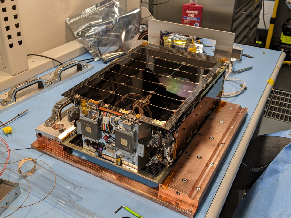
The above photo showed the antennas on the +Z side, which are in the middle of the spacecraft body, between the solar panels. The antennas on the -Z side can be seen in this other photo. Note that here the solar panels are folded over the spacecraft body.
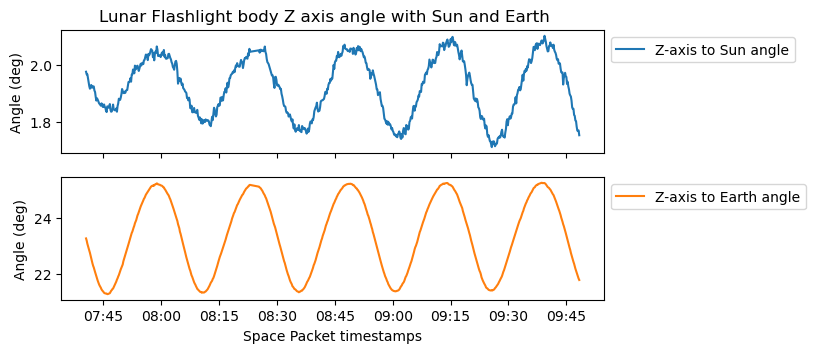
I have also taken from HORIZONS the spacecraft position in geocentric ICRF coordinates at 7:30 TDB in order to compute the Earth vector as seen from the spacecraft. We also assume that this vector doesn’t change much during 2 hours. The angle between the Sun and Earth vectors is 23 degrees. The spacecraft is pointing its solar panels, and hence its antennas on the +Z side, towards the Sun. Since the Earth is not too far off from the Sun from the point of view of the spacecraft, it can use its +Z side antennas to communicate with Earth. The plot below shows the angles between the Z-axis and the Sun and the Earth.
The antennas of Lunar Flashlight are low-gain circularly polarized patch antennas for X-band. This paper indicates that the antennas are “two pairs of INSPIRE-heritage low-gain antennas”. INSPIRE is just another name for the IRIS radio. In the paper X-Band electronics for the INSPIRE Cubesat deep space radio we can see more details about these antennas. The next figure is taken from this paper and shows the radiation pattern for the receive antenna (7.2 GHz). The radiation pattern for the transmit antenna (8.4 GHz) would be similar.
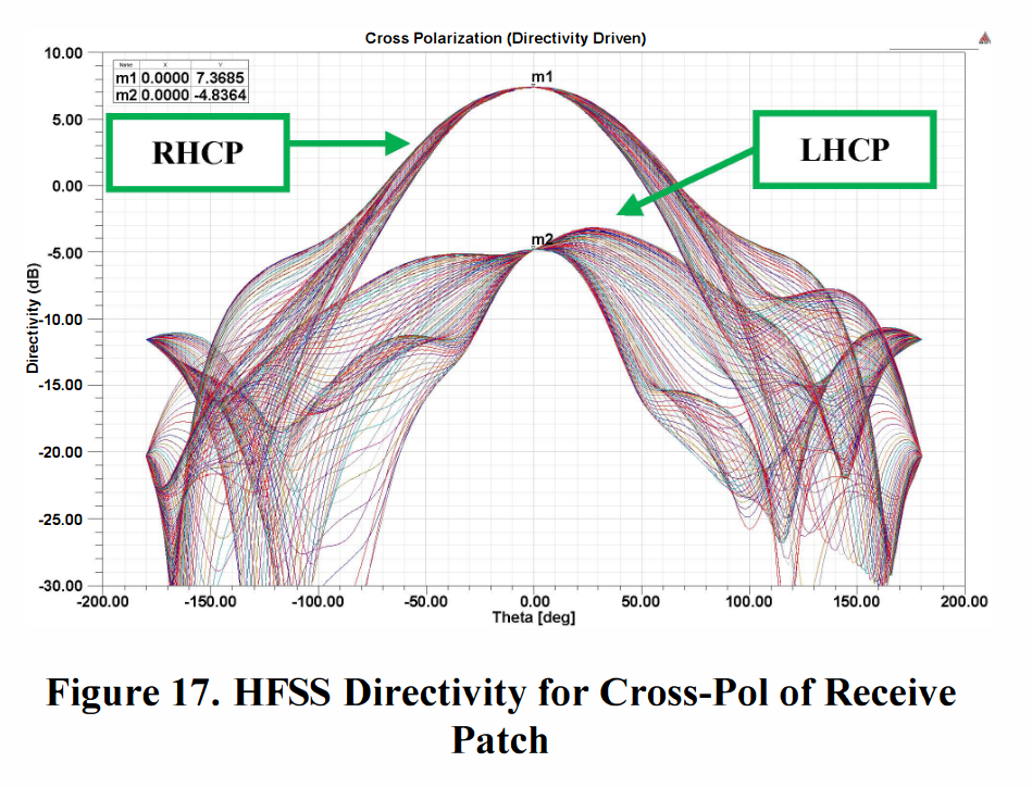
We can see that the gain reduction at 23 degrees from boresight is around 1 dB, which is not much. This shows why the spacecraft can afford to point its solar panels and antennas directly to the Sun in this case. I wonder how the spacecraft attitude would be configured for situations in which the Sun-spacecraft-Earth angle is much larger. Probably it depends on whether the spacecraft is being tracked by a groundstation (prioritizing pointing the antennas to Earth) or not (prioritizing pointing the solar panels to the Sun).
Code and data
The GNU Radio flowgraph and Jupyter notebook used in this post can be found in this repository. It also contains the AOS frames decoded from the IQ recording.
Good as usual but , Can I get the wav file or the IQ file?
Unfortunately the recording hasn’t been shared publicly, as far as I know. Sorry.