Lucky-7 is a Czech Amateur 1U cubesat that was launched on July 5 together with the meteorological Russian satellite Meteor M2-2 and several other small satellites in a Soyuz-2-1b Fregat-M rocket from Vostochny. The payload it carriers is rather interesting: a low power GPS receiver, a gamma ray spectrometer and dosimeter, and a photo camera.
It transmits telemetry in the 70cm Amateur satellite band using 4k8 FSK with an Si4463 transceiver chip. Additional details about the signal can be found here.
After some work trying to figure out the scrambler used by the Si4463, I have added a decoder for Lucky-7 to gr-satellites. This post shows some of the technical aspects of the decoder.
The framing used by Lucky-7 is really simple: the 16 bit syncword 0x2DD4 is followed by 35 bytes of data and 2 bytes of CRC-16. The data is scrambled using the default register settings for the Si4463.
In principle, that scrambler is a PN9 using the polynomial \(x^9 + x^5 + 1\) and seed 0x1FF. This should be similar to the scrambler of the TI CC1101 that I already have implemented as part of my Reaktor Hello World decoder. However, unlike Texas Instruments, which has detailed design note explaining the PN9 scrambler, I have not found good documentation from SiLabs for the Si4463 scrambler.
After trying out various things and reaching a dead end, I asked the Lucky-7 team if they could make me a recording of a Si4463 transmitting a scrambled packet whose payload is full of zeros. Such a packet shows the scrambling sequence directly. Jaroslav Laifr was kind enough to make a recording for me.
When analyzing Jaroslav’s recording, which had scrambled 64 byte frames full of zeros, I saw that the scrambling sequence is
87 b8 59 b7 a1 cc 24 57 5e 4b 9c 0e e9 ea 50 2a
be b4 1b b6 b0 5d f1 e6 9a e3 45 fd 2c 53 18 0c
ca c9 fb 49 37 e5 a8 51 3b 2f 61 aa 72 18 84 02
23 23 ab 63 89 51 b3 e7 8b 72 90 4c e8 fb c1 ff
I immediately recognized that sequence.
Recall that the TI PN9 scrambler is implemented in GNU Radio as shown in the figure below.
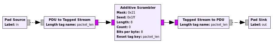
The bits per byte parameter is set to 8 because to scramble each byte, the 8 least significant bits from the scrambler shift register are taken, and then the shift register is shifted 8 times before scrambling the next byte. This produces the sequence
ff e1 1d 9a ed 85 33 24 ea 7a d2 39 70 97 57 0a
54 7d 2d d8 6d 0d ba 8f 67 59 c7 a2 bf 34 ca 18
30 53 93 df 92 ec a7 15 8a dc f4 86 55 4e 18 21
40 c4 c4 d5 c6 91 8a cd e7 d1 4e 09 32 17 df 83
You’ll recognize that sequence from the TI design note, where the first 512 bytes of the sequence are listed.
Another way, which is perhaps more common, to generate the scrambling sequence is to work in a bit by bit fashion. Thus, to scramble a bit of input, the least significant bit of the scrambler shift register is used, and then the shift register is shifted once before passing to the next bit. In GNU Radio, this is achieved by setting the bits per byte parameter of the Additive Scrambler block to 1 instead of 8 and feeding it unpacked bits (so that each byte contains only one bit of input).
When the PN9 polynomial is run in a bit by bit manner, it produces the following sequence:
ff 87 b8 59 b7 a1 cc 24 57 5e 4b 9c 0e e9 ea 50
2a be b4 1b b6 b0 5d f1 e6 9a e3 45 fd 2c 53 18
0c ca c9 fb 49 37 e5 a8 51 3b 2f 61 aa 72 18 84
02 23 23 ab 63 89 51 b3 e7 8b 72 90 4c e8 fb c1
You can also find this sequence in the TI design note if you read carefully: look at section 3.3 and take the least significant bit of each register state listed there.
You’ll notice that, except for the initial 0xff byte, this sequence is the same as the one that the Si4463 uses. So it seems that the Si4463 uses the same PN9 as the TI CC1101, but it runs it in a bit by bit manner instead of byte by byte, and skips the first output byte.
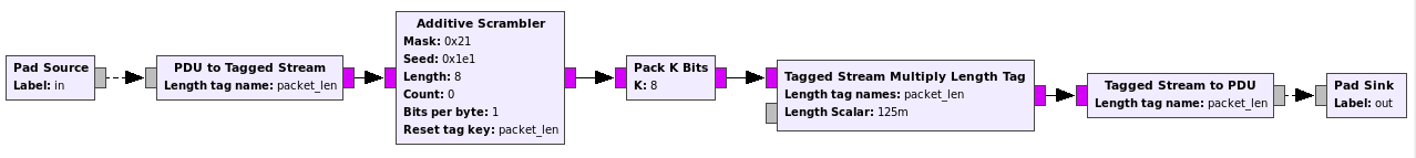
In GNU Radio, skipping the first output byte can be achieved by setting the seed value to the correct shift register state that the scrambler which starts by 0xff would have after having shifted out one byte. Taking into account the fact that the endianness of the shift register in GNU Radio is reversed (shifts are done to the left, instead of the right), this is 0x1e1. Note that 0xe1 is just 0x87, the second output byte, with the bits reflected (and the first 0x1 comes from the MSB of 0xb8).
Taking this into account, the Si4463 scrambler block in GNU Radio can be seen in the figure below. It takes unpacked bits as input and outputs packet bits.
It also turns out that the CRC-16 used by the Si4463 is the same that the CC1101 uses, so the CRC check block has been reused from the Reaktor Hello World decoder.
Some Lucky-7 frames decoded from a recording I made on July 7 are shown below.
0000: 80 20 00 00 00 00 00 00 00 00 00 00 00 00 00 00
0010: 00 00 00 00 00 00 00 00 00 00 00 00 00 00 00 00
0020: 00 00 00

0000: 80 10 00 00 00 00 ff ff ff ff ff ff ff ff ff ff
0010: ff ff 00 05 00 05 00 e4 0d 00 00 00 07 d1 07 d1
0020: 07 d1 00

0000: 80 20 01 00 00 3c 00 00 00 00 00 00 00 00 00 00
0010: 00 00 00 00 00 00 be 02 ce 00 0d 86 a0 00 00 00
0020: e8 00 00

0000: 80 10 01 00 00 3c 67 20 00 fb aa 09 01 23 c7 17
0010: 1c 27 00 05 00 05 ba 16 12 21 af 40 07 d1 07 d1
0020: 07 d1 00

0000: 80 20 02 00 00 78 00 00 00 00 00 00 00 00 00 00
0010: 00 00 00 00 00 00 be 3e d1 00 0d 00 67 03 00 00
0020: e8 00 00

0000: 80 10 02 00 00 78 68 20 01 07 aa 09 74 2c 93 14
0010: 07 26 00 05 00 05 ba 16 10 21 af 40 07 d1 07 d1
0020: 07 d1 00

0000: 80 20 03 00 00 b4 00 00 00 00 00 00 00 00 00 00
0010: 00 00 00 00 00 00 be 7a d1 00 0d 00 67 03 00 00
0020: e8 00 00

0000: 80 10 03 00 00 b4 68 20 00 df aa 09 dd 15 1d 14
0010: 03 26 00 05 00 05 b9 16 0f 21 af 40 07 d1 07 d1
0020: 07 d1 00

0000: 80 20 04 00 00 f0 00 00 00 00 00 00 00 00 00 00
0010: 00 00 00 00 00 00 be b6 d1 00 0d 00 67 03 00 00
0020: e8 00 00
Note that these frames do not follow the format given in the Lucky-7 protocol description. In particular, the callsign and satellite name are nowhere to be found. My guess is that the second byte is some sort of packet type indicator (0x10 or 0x20), and the third byte is a packet counter, which runs independently for each packet type. Let’s see if the satellite team can give more information about the format.
Wonderful & very interesting write-up, as always.
Ref. the alternating 0x10 / 0x20 bytes, I recall that some of the cubesats have been alternating between A/B redundant transmitters and specifying which transmitter each downlink originated from with an indicator byte.
So, while they could mean anything, that’s one possibility that comes to mind.
-Scott, K4KDR
Scott, the alternating address A/B is typical for an “overview” kind of memory download in Lucky-7 comm scheme (to capture as much as possible during single pass, if fading/interference is present). The address 1000h is intended for the general satellite HK Status data (such as Main/Redundant OBC flag {00xxxx or 80xxxx respectively}, 3-axis gyro, OBC current, temperature of PA and OBC,…), the address 2000h then for the GPS 1 minute records (if was turned on). Capture decoded here is from initial commissioning stage. Each experiment command first erase the particular OBC memory block, then fills it with data. Looking forward to upcoming observations and decodings!