I have a DF9NP 10MHz GPSDO that is based on a u-blox LEA-5S GPS receiver. Essentially, the LEA-5S outputs an 800Hz signal that is used to discipline a 10MHz VCTCXO with a PLL. The LEA-5S doesn’t have persistent storage, so an I2C EEPROM is use to store the settings across reboots.
Lately it seemed that the reading of the settings from the EEPROM had failed. The u-blox was always booting with the default settings. This prevents the GPSDO from working, since the default for the timepulse signal is 1Hz instead of 800Hz. Here is the summary of my troubleshooting session and the weird repair that I did.
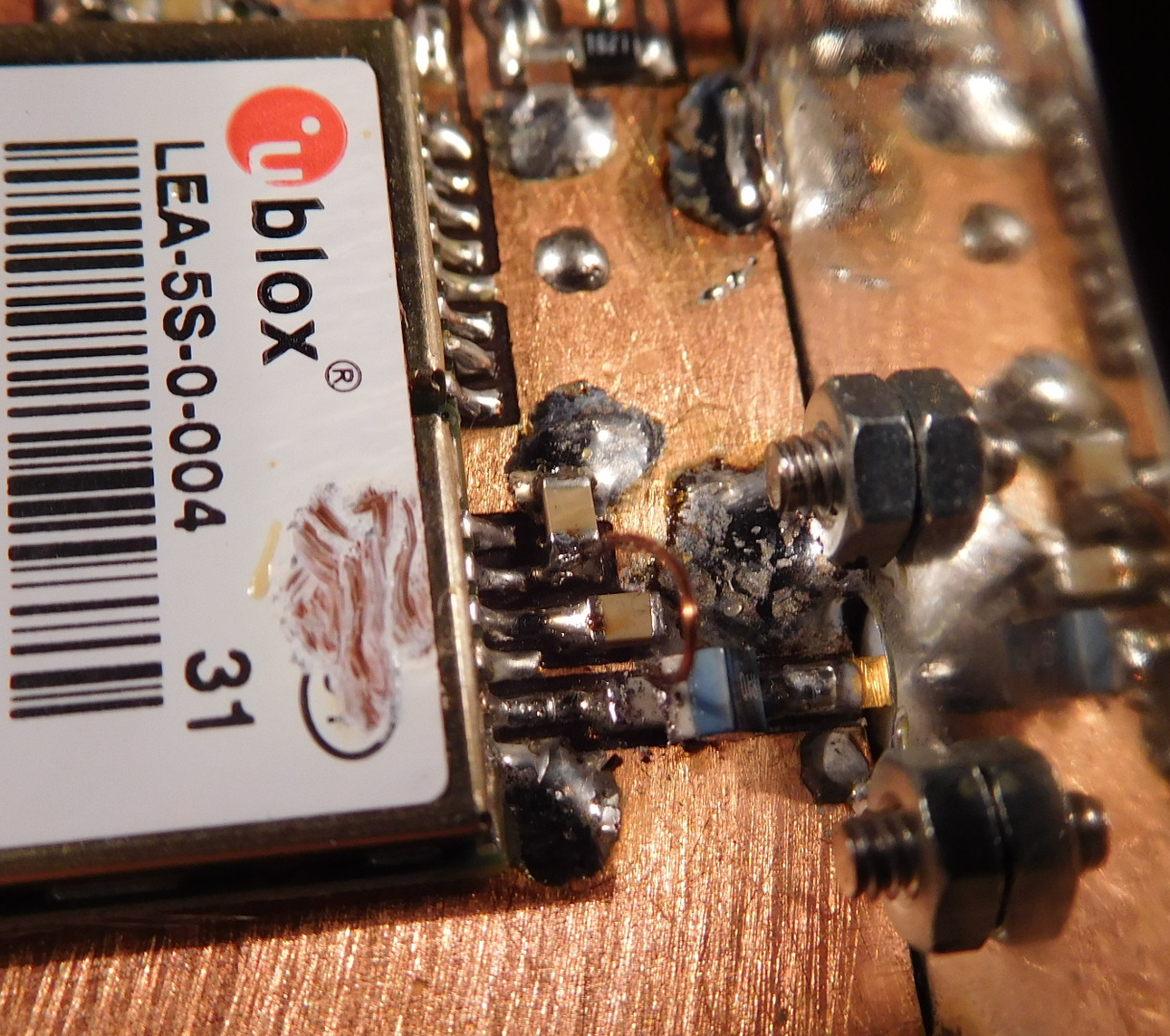
To be honest, this LEA-5S wasn’t working perfectly either. The antenna bias voltage had failed some time ago. The bias voltage monitor always detected a short circuit on the antenna pin, and even if the monitor was disabled, the u-blox wasn’t able to supply a voltage to the antenna. Luckily this was easy to fix by adding an external bias circuit composed of a capacitor and inductor (see the figure below).
In any case, today I decided to troubleshoot the reading of the I2C EEPROM. When the u-blox boots up it should read all the settings from the EEPROM, so I started by probing the SDA line with my oscilloscope and switching the GPSDO on. There was not much on the SDA line. The line was held high (at 3.3V) almost all the time, with an occasional brief pulse to 0V. Probing the SCL line instead of the SDA line revealed what seemed to be a perfectly functional clock.
Since I wanted to see what the occasional SDA pulses were, in relation to the clock, I now probed both lines simultaneously. My surprise wa that suddenly the I2C interface appeared to be working: the data was now present on the SDA line. I observed that even if I probed the SCL line with a probe disconnected from the oscilloscope and with its ground clip not attached, the SDA line had data. If I didn’t probe the SCL line, the SDA didn’t have any data (only the occasional pulses). This behaviour was perfectly repeatable.
I checked carefully that this wasn’t a mechanical effect. Applying pressure with the probe on the SCL line could be forcing or bridging a broken solder joint. After it was clear that this wasn’t the case, I thought about the electrical effect of probing the SCL line with a probe disconnected from the oscilloscope (or with a multimeter lead, which caused the same behaviour). The probe just adds a small capacitance to ground. That should be all.
I had no idea how a small capacitance to ground could cause any effect in such a low speed bus, and even more, fix a seemingly broken I2C interface. In any case, I decided to trust what I was seeing and solder a 10pF through-hole capacitor between the SCL line and ground. This was the smallest capacitor I could find. Surprisingly, this fixed the I2C interface. I now had data in the SDA line and the u-blox could read its settings correctly. Writing settings to the EEPROM was also working.

I have no idea how adding the 10pF capacitor has fixed the I2C bus. I find this very intriguing and surprising. The SDA and SCL lines are connected directly between the u-blox and the EEPROM, as shown in the LEA-5 hardware integration manual, since the u-blox has internal pull-ups.
I found similar behaviour in some high speed SPI bus run over a >30cm backplane. It failed bellow -20°C but worked when probing with the oscilloscope, making it difficult to diagnose. But it was evident a signal integrity issue, agravated by higher driving currents at low temperatures. The right fix is not to add a deliberate capacitance to the bus, as that only changes the waveform ringing shape and could increase crosstalk, but damping the ringing with 22R series resistors. That works for reducing crosstalk as well.
That is interesting. I hadn’t considered ringing to be an issue. The main problem is that since probing with the oscilloscope fixes the issue, I can’t measure how much ringing there is. In the oscilloscope the waveforms look very clean.
Here the I2C lines are short. The I2C pins on the u-blox are in the corner next to the EEPROM.
In any case, I wanted this fixed quickly, so putting a capacitor in parallel was easier than breaking the lines and putting 22R resistors. Nevertheless, it is good to know the correct fix.