David Rowe always insists that you should simulate the bit error rate for any modem you build. I’ve been intending to do some simulations of the decoders in gr-satellites since a while ago, and I’ve finally had some time to do so. I have simulated the performance of the LilacSat-1 decoder, both for uncoded BPSK and for the Viterbi decoder. This is just the beginning of the story, as the code can be adapted to simulate other modems. Here I describe some generalities about BER simulation in GNU Radio, the simulations I have done for LilacSat-1, and the results.
My starting point has been the berawgn.py script that is included in GNU Radio. This script shows how to use vector sources and sinks to simulate the BER of uncoded QPSK. A vector source is a GNU Radio signal source that uses a Python list to generate its output. It runs through the list, generating an output sample per item in the list and then stops (optionally it can be set to repeat, but this functionality is not used for BER simulation). A vector sink is a GNU Radio sink that stores the samples it receives in a Python list. The idea of berawgn.py is simple: generate a random list, use it as the input of a vector source, map to a QPSK constellation, add some noise, decode the QPSK and store into a vector sink. Finally, the data stored by the vector sink is compared with the original list and the BER is computed. The script then runs the flowgraph once for each Eb/N0 and plots the results.
The drawback of this approach is that it can’t be applied to a complete PSK receiver. Once you pass to a PSK signal with several samples per symbol and you perform clock and carrier recovery, it is not guaranteed that the input and the output line up exactly, since the receiver may slip some bits. To solve this issue, I’ve used a G3RUH scrambler.
A G3RUH scrambler can be used to test for BER, because if the input to the scrambler is constantly 1, the output of the scrambler looks random and after receiving and descrambling we should see a constant stream of 1’s. A single bit error causes 3 zeros in the output of the descrambler. If the BER is low, the probability that the 3 zeros corresponding to each bit error coincide is very low, so we can get a very good estimate of the number of bit errors by counting the number of zeros in the output of the descrambler and dividing by 3. Since the scrambler is asynchronous, it is tolerant to bit slip.
Similarly, I have used differential encoding after the scrambler to account for any possible phase flip in the BPSK signal. Each bit error will produce two bit errors at the output of the differential decoder, so in the end we have to divide the number of zeros by 6 to get the number of bit errors.
With this in mind, the uncoded BPSK receiver for LilacSat-1 can be tested. The same ideas can be applied to any other uncoded receiver. For the Viterbi decoder there is an extra issue: there is an ambiguity about how to pair the input symbols to the Viterbi decoder. The usual approach to resolve this ambiguity is to run two Viterbi decoders in parallel. One runs on the stream of symbols, and the other one runs on the stream of symbols delayed one sample, so that the pairs of symbols that each of the decoders take are different. At any moment in time, only one of the decoders is producing valid data and the other decodes garbage. If a single bit slip occurs, the decoders change places, so the one which produced valid data now decodes garbage and vice versa.
To handle this in the BER simulation, we assume that one of the decoders is synced up correctly, so it should be working, while the other is one sample out of sync, so it should be producing random data. Thus, any time that a bit error happens, the “good” decoder produces a 0, while the “bad” decoder produces a 0 with 50% chance and a 1 with 50% chance. If we determine to count a bit error only when both decoders output a 0, we are only counting 50% of the bit errors on average, but later we can compensate for that in the BER calculation.
In these simulations I am running exactly the same decoders that are used in the LilacSat-1 receiver in gr-satellites except for one detail: I am not using the Feed Forward AGC block. There are several reasons for this. First, it is very CPU intensive, so it is a huge bottleneck for the simulations, which already take quite long to run. Second, for some reason it seems that it causes problems that disturb the Viterbi decoder. Third, I have noted that the performance is much better if the amplitude of the signal is 0.5, rather than 1 or 2. This is specially notable for the Viterbi decoder. Currently, the Feed Forward AGC is using a Reference level of 2 (which sets an amplitude of 2). In good SNR this makes the Viterbi decoder perform badly. In lower SNR the effect is more subtle, as the noise amplitude is higher, so the AGC sets the amplitude of the signal to something smaller than 2. In any case, it is clear that the current AGC is not good, both in terms of CPU requirements and BER performance at a high SNR. I will have to try other AGC approaches that work well both for the packetized downlink as well as for a continuous transmission.
I have added all the Python scripts I have used to gr-satellites, in the apps/ber folder. To test that the carrier and clock recovery is working fine, I set a phase offset of 45º and a clock offset of 2 samples. Of course, the loops have to converge, so the first 1000 output samples are thrown and not taken into account for the BER calculation.
The image below has been produced by lilacsat1.py. There we can see the BER performance for the LilacSat-1 decoder, both for uncoded BPSK and for the Viterbi decoder. The uncoded BPSK performance follows very closely the theoretical performance, with very little implementation loss. In comparison with the Viterbi simulation in dsplog, there is a fraction of a dB of implementation loss in the LilacSat-1 Viterbi decoder.
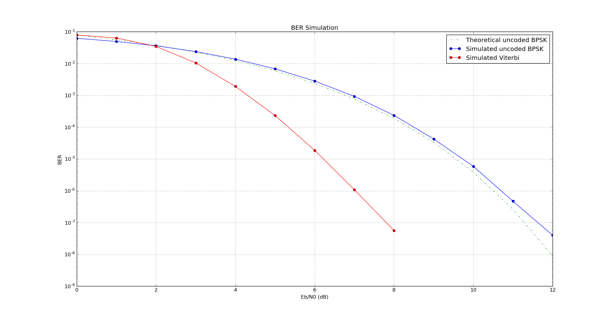
This plot has been obtained with a signal amplitude of 0.5. With a different amplitude (say, 1 or 2), the results are much worse.
Fine business Daniel.
Using the scrambler is an interesting idea. For my Octave and C based modems I have a state machine based test frame system that generate fixed frames on the tx, then syncs up to them at the rx, and counts bit errors. This is a little more direct than your method of counting errors, but using a scrambler has the advantage of more random data than the fixed sequences I use.
Looks like your tests have found an issue with the AGC – cool, that’s why we do them! PSK should be insensitive to amplitude and not need an AGC, e.g. in the FreeDV PSK modems we ignore amplitude completely. However FEC decoder sometimes require amplitude scaling for the input symbols.
Further enhancements to your tests would be simulating sample clock offsets (e.g. 10 or 100ppm), having a frequency offset, a Doppler profile on the frequency offset, and measuring acquisition time.
But you have to be a real modem nerd like me to go to all that trouble 🙂
Cheers,
David
Hi Daniel,
As a regular visitor of your blog and a regular user of your flowgraphs, let me first say thank you so much for your work!
I think that your BER script can be improved by not using the G3RUH scrambler fed with all “ones” to generate a random sequence, but rather rely on a true PRBS generator which is fairly easy to implement. Then, the degree of the PRBS essentially determines the confidence level to which you can test to a certain BER (i.e. a larger degree allows you to test for lower BER at the same confidence level, but of course increases the test time). Then, in order to determine the BER, you can perform a cross correlation of the received PRBS stream at the output of the Viterbi decoder versus the original PRBS sequence. From the value of the crosscorrelation of each complete PRBS sequence you can then determine BER for that sequence.
73,
Wouter Jan PE4WJ
Daniel, Just to follow up on Wouters suggestion, Tim built PRBS sink/sources in gr_mapper a couple of years back for this exact purpose. See: https://www.gnuradio.org/blog/bit-error-rate-testing
-Ian