In a previous post, I talked about the possibility of changing the transmit frequency of a Vaisala RS92-SGP radiosonde by modifying the settings on its EEPROM. The lowest frequency you can achieve using this method is 400MHz and the highest probably depends on the particular unit, but it is somewhat between 410MHz and 423MHz. There are also reports of very low output power on the highest frequencies (I’ll explain why below). Clearly, this can’t be used to make the radiosonde transmit in 430MHz, inside the 70cm Amateur band. In fact, from what I’ve read online, the impression is that it’s not possible to modify the radiosonde to make it transmit in 430MHz. However, I wanted to try to feed an external reference to see what happened. Short story: it doesn’t work either. However, I discovered some interesting information about the RF section of the RS92-SGP along the way.
The RF board of the RS92-SGP derives its frequency from a 16.367MHz signal that is generated using a crystal oscillator in the GPS receiver section of the main board. You can see the pin where this signal goes to the RF board in the brmlab hardware description or in the image below. My idea was to replace this signal with an external signal. Removing the shielding on the RF board requires lots of patience, solder wick and flux. However, it’s probably worth the effort, because probably the cleanest way to inject an external reference is to remove the 100R resistor that connects the 16.367MHz signal through to the main IC clock pin (this resistor is also marked below in red).
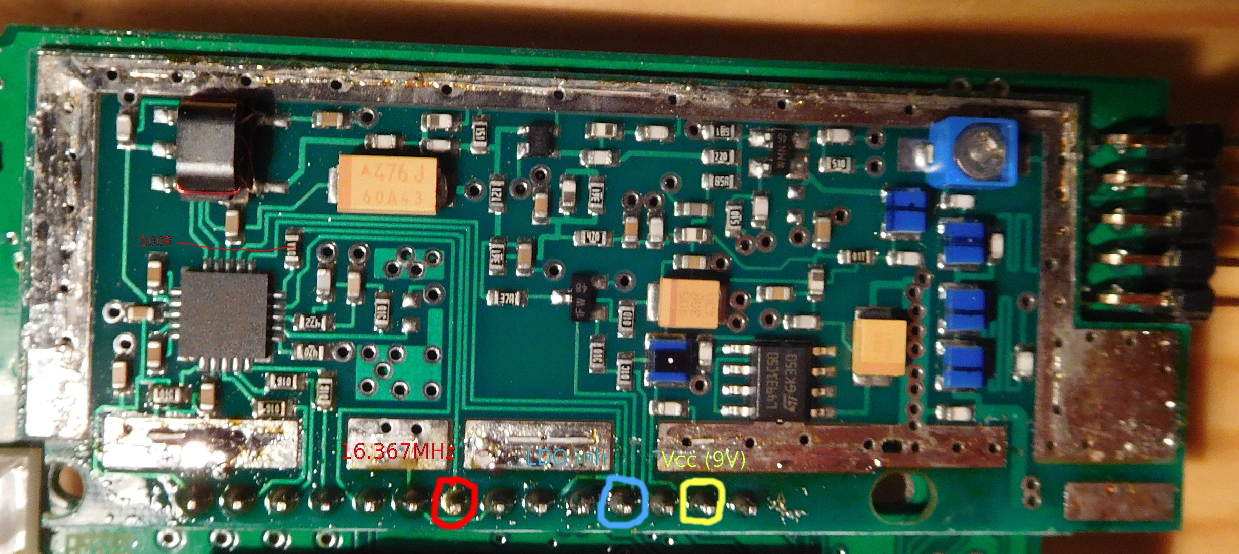
When removing the shielding, I discovered by accident another important element. If you look closely at the image above, you might see that I’ve cut the trace that comes from the pin marked in blue. This trace goes through a 10k resistor to the inhibit pin of an L4931 5V LDO regulator. This regulator powers the final RF amplifiers. Also, it turns out that with this trace cut, the rest of the circuit on the RF board pulls the inhibit pin to 9V, disabling the LDO. Therefore, after cutting this trace, I got very reduced output power, since the finals where switched off. The blue pin connects through to the main board, and then presumably to the main CPU, which drives this line low during normal operation to enable the finals. There are some reports that if the radiosonde’s main voltage falls below 7V, the CPU will drive this line high to enter a low power mode. I repaired this by soldering a fine enamelled wire between the blue pin and 10k resistor, thus replacing the broken trace, and proceeded with my tests with the external reference.
The 16.367MHz signal on the board is 3Vpp, so after playing for a bit with my Si5351A, I had a signal of the same frequency and similar voltage. I’ve removed the 100R resistor and I’m feeding the external signal through a 0.1uF capacitor to the resistor pad that connects to the IC clock pin. I’m also using a 6dB attenuator on the output of the Si5351A to give it a good impedance match. The radiosonde transmitted fine with the external 16.367MHz signal, so I started to increase the frequency.
What I observed is that when increasing the frequency, it reached some point where the radiosonde would alternate erratically between normal power and low power mode. The CPU was doing this by toggling the blue pin between 9V and ground. I don’t know why it does that. Perhaps it detects some abnormal condition in the RF section, such as high SWR or something similar. If the frequency of the external reference is increased further, then the CPU sets low power mode all the time.
I overrode this by disconnecting the blue pin and connecting the trace to ground. Keep in mind that I have this trace already disconnected from the pin. You’ll have to break this trace if you want to do this modification. With this modification, the radiosonde stays in normal power mode. However, when I proceeded to increase the frequency further, the transmitter IC failed to lock properly and the only thing I got was some kind of noise bump wandering across the band. At this high frequencies, the system is very sensitive to small capacitance variations on the transmit chain. Just placing the oscilloscope probe on some of the elements made the transmitter change from transmitting properly to failing to lock or vice versa. The highest frequency that can be achieved reliably is more or less the same as by changing the EEPROM settings. I also tried to hold the inhibit line to 9V (yellow pin) to see if the frequency limit problem was something with the final amplifier or subsequent filtering. This makes not much difference in the frequency range you can achieve.
What you can do with this method is to get a lower frequency, which is not possible by changing the EEPROM settings. I could get a frequency as low as 383.7MHz, by setting the reference to 15.7MHz.
It seems that the main limit in the frequency range of the RS92-SGP is the main IC, which fails to lock when commanded to a too high or low frequency (either via EEPROM setting or external frequency reference). I’m thinking about building a mixer to convert the frequency from 400MHz to 430MHz.
My RS92 is up and running in high RF power mode now. Thanks for the insights. I’m getting an error message from auto_rx saying the RS92 does not have “GPS lock”. I’m just wondering if there is something further must be done in order to get GPS lock? I have the RS92 sitting in the window in my lab.
Thanks,
Charlie
Sorry, but I don’t know what your problem with the GPS might be. I haven’t tested the GPS of the RS92 after recovering the radiosonde from the field.