This post belongs to my series about LTE. In the LTE uplink, the PUSCH (physical uplink shared channel) is the channel used to trasmit data from the UEs (phones) to the eNB (base station). It plays a role analogous to the PDSCH (physical downlink shared channel), which is used to transmit data in the downlink. In this post I will decode the PUSCH in a recording that I made of my phone uplink a couple years ago.
The PUSCH uses the same kind of techniques as the PDSCH for transport block coding, so all the Turbo code implementation and related algorithms from my post about the PDSCH will be re-used here. However, there is an important difference between the PDSCH and the PUSCH that makes decoding the PUSCH much harder. The LTE downlink is, in a certain sense, a self-descriptive signal. The UEs don’t know in advance the configuration that will be used to transmit each transport block in the PDSCH, because the eNB decides it on the fly. Therefore, the eNB announces PDSCH transmissions in the PDCCH (physical downlink control channel).
When I decoded the PDCCH and PDSCH, the only slightly clever thing that I had to do was to find the RNTIs (radio network temporary indicators). These are 16-bit numbers that are used to address each PDSCH transmission. There are some of them which are statically allocated to some broadcast purpose (SI-RNTI, P-RNTI, RA-RNTI), and the C-RNTIs, which are individually assigned to each UE. The CRC-16 of the PDCCH DCIs is XORed with the RNTI to which the transmission is addressed. At any time, a UE knows the set of RNTIs that it is monitoring, so it calculates the CRC-16 of the received DCI, computes its XOR with each of its assigned RNTIs, and compares the result with the CRC-16 in the DCI. If there is a match, the DCI is accepted. This is a way of filtering out messages without spending additional bits to put the RNTI in a field in the DCI.
When we are monitoring an LTE downlink, we don’t know which RNTIs are being used. With some cleverness, if the SNR is good enough, we can detect and select each PDCCH transmission by hand (it is necessary to guess the REGs that it occupies and the DCI length) and then, assuming that we have decoded the DCI with no bit errors, obtain the RNTI as the XOR of the calculated CRC and the received CRC. This is what I did in the post about the PDCCH. If we were monitoring the LTE downlink for a longer time, this trick wouldn’t even be necessary. The C-RNTIs assigned to the UEs are communicated to them in a RAR transmitted with the RA-RNTI, as a response to their PRACH (see the post where I analyze this in Wireshark). So a downlink monitor application can simply watch the SI-RNTI, P-RNTI and RA-RNTI, and add any C-RNTIs to a list of known connected UEs when it sees a RAR. The C-RNTIs can be removed from this list after a period of inactivity, because the UE would have been sent to the idle state by the network. This idea really shows that it is possible to decode everything in the LTE downlink without doing clever blind decoding tricks.
In contrast, the LTE uplink is not self-descriptive. The eNB defines the configuration of each PUSCH transmission when it sends the uplink grant to the UE. So the UE doesn’t need to communicate this configuration again to the eNB when it transmits in the PUSCH. The information that describes the PUSCH transmissions is effectively in the PDCCH in the downlink, and in this case I don’t have a recording of the downlink that matches my uplink recording. This makes decoding the PUSCH much more difficult, but nevertheless not impossible. With some clever ideas and blind decoding tricks we can usually find all the information we’re missing. In the rest of this post, I describe how to do this in detail. It will be long and quite technical.
Finding the C-RNTI
The main obstruction for decoding a PUSCH transmission is finding the C-RNTI. This is required because the PUSCH bits are scrambled with a pseudorandom sequence that is initialized with the RNTI (as well as other variables). There are other parameters that are needed to decode a PUSCH transmission, such as the set of resource blocks that it occupies, the modulation, the transport block size, and the redundancy version. However, the RNTI is probably the most difficult of these to find because it is a 16-bit number. If the SNR is not too bad, the allocated resource blocks can be found from a power measurement in the spectrum, and the modulation can be found from looking at the constellation. The transport block size only has about a dozen possible options once we know the number of resource blocks and the modulation. But for the RNTI the 16-bit search space is too large.
An implementation that has been well tested and optimized might be able to compute the RNTI by brute force. The CRC of the transport block is a CRC-24, so even if all the 65536 possible RNTIs and all the possible transport block sizes are tried, the rate of false positives will be low (here a false positive is defined as a wrong choice of parameters that nevertheless gives a correct CRC-24). But in this case I have an inefficient Turbo decoder implemented in Python and I’m writing everything as I go, using the recording to check that my implementation is correct. So brute force search of all the RNTIs is not a good option because if something doesn’t work it will be difficult to tell if it is because I’m using the wrong RNTI or because there is something else wrong in my code.
Therefore, I began this project by looking at where else the C-RNTI is used in the LTE uplink. It is typical to use the RNTI whenever something that needs to be different for each UE must be generated. So perhaps one of these uses could help us find or narrow down the C-RNTI.
I found that PUCCH formats 2, 2a and 2b looked promising for this. As described in Section 5.4.2 of TS 36.211, these PUCCH formats transmit 20 bits which are scrambled with a pseudorandom sequence initialized with the value\[(\lfloor n_s / 2 \rfloor + 1) \cdot (2 N_{\mathrm{ID}}^{\mathrm{cell}} + 1) \cdot 2^{16} + n_{\mathrm{RNTI}}.\] The value \(n_s\) is the slot number within the radio frame (it counts from 0 to 19). We don’t know the radio frame synchronization of this uplink recording, but hopefully it is not too difficult to find (and I’ll get back to this later on). We know that the cell ID is 378 (I looked at this in my phone when I did the recording). So the only unknown value in the scrambling sequence generation is the RNTI.
PUCCH formats 2, 2a and 2b are used to send CQI (channel quality indicator) from the UE to the eNB. Therefore, they are sent quite often (in this case typically every 5 ms) and perhaps their data is somewhat predictable. For example, for a UE that isn’t moving (in this case my phone was on my table when I made the recording), adjacent transmissions of these PUCCH formats will have the same or very similar data. But the scrambling sequence will generally be different for each transmission because it also depends on \(n_s\). So my thinking was to take advantage of this to try to find the \(n_{\mathrm{RNTI}}\).
Unfortunately this idea doesn’t work as well as I had thought initially, because the pseudorandom sequence depends linearly on \(n_{\mathrm{RNTI}}\) (more formally, it is an affine function). In practice, this means that additional transmissions aren’t giving us any new information to constrain the RNTI. We can in fact descramble all the transmissions with pseudorandom sequences obtained with \(n_{\mathrm{RNTI}} = 0\) and the correct values for \(n_s\) and \(N_{\mathrm{ID}}^{\mathrm{cell}}\). What we get is the vectors of 20 bits all scrambled with the same pseudorandom sequence generated by using the initialization value \(n_{\mathrm{RNTI}}\). By doing this, we have eliminated the dependency on \(n_s\). Two transmission that had identical data will also be identical when scrambled by this common pseudorandom sequence, but this doesn’t tell us which is the pseudorandom sequence (or the RNTI that generated it) unless we know the data that was transmitted.
Something that we can use to our advantage is that the 20 bits that are transmitted in PUCCH formats 2, 2a, and 2b are encoded with a block code. Section 5.2.3.3 in TS 36.212 describes how 10 information bits (or up to 13 information bits in the latest LTE releases) are encoded as 20 bits by using a Reed-Muller code. Assuming that the UE is transmitting only 10 information bits, this gives us a (20, 10) linear block code. We can find the values of \(n_{\mathrm{RNTI}}\) such that when the scrambling sequence is initialized with\[(\lfloor n_s / 2 \rfloor + 1) \cdot (2 N_{\mathrm{ID}}^{\mathrm{cell}} + 1) \cdot 2^{16} + n_{\mathrm{RNTI}}\]using that particular value, then the descrambled 20-bit vector belongs to the (20, 10) block code. Again, everything here is linear, so the set of solutions will be an affine subspace of dimension 6 in the 16-dimensional vector space of RNTIs (the dimension of the solution space is 6 because \(16 – 10 = 6\)). Using different PUCCH transmissions gives the same solution, so this doesn’t give any additional information. However, this manages to reduce the number of RNTI candidates to only 64 from the original pool of 65536.
There are two ways to to find the solution space. The first is by doing some linear algebra. This is the most efficient way. The second is by brute force testing all the 65536 RNTIs. This is very easy to implement, and it is relatively fast, even in Python. This is the approach I have followed. To check if the descrambled 20-bit vector belongs to the block code, I have precomputed a parity check matrix for the block code. Thus, I just need to multiply the parity check matrix by this vector and check if the result is zero.
This method manages to reduce the set of RNTI candidates to 64 elements. I consider the problem of decoding PUSCH with blind search in this reduced set of candidates much more tractable than with the initial set of 65536 RNTIs. Therefore, I’m happy with how this idea has worked and will not try to use more information in the PUCCH format 2, 2a and 2b to try to reduce the candidate set even more. It might be possible that by putting some constraints on the data that is encoded in the 10 information bits, further reduction of the candidate set can be done. However, note that to reduce the set to just a single candidate, 6 information bits out of the 10 would need to be known (or we would need an equivalent set of linear or non-linear constraints on the information bits).
Radio frame synchronization
The method described above requires finding the synchronization to the radio frame, because it requires knowing the slot number \(n_s\). The way in which I do this uses the fact that the 12 resource elements in each PUCCH symbol are equal to a common value multiplied by a sequence\[r_u^\alpha(n) = e^{i\alpha n}r_u(n),\]where \(\alpha = \pi k/6\) for some \(k = 0, 1, \ldots, 11\). This applies to the data symbols of PUCCH formats 1, 1a, 1b, and formats 2, 2a, 2b, as well as to the DMRS symbols. In my post about the PUCCH, I already found that \(u = 18\) (\(u\) is usually set to be the cell ID modulo 30), and found the value of \(k\) for each PUCCH symbol by detecting it with a correlation.
The value of \(k\) used for each symbol is defined in several sections of TS 36.211. The information is somewhat scattered and a bit difficult to follow, but the summary is that \(k\) is equal to a number \(\bar{n}_{\mathrm{cs}}^{(\widetilde{p})}(n_s, l)\), where \(n_s\) denotes the slot number within the radio frame and \(l = 0, 1, \ldots, 6\) denotes the symbol number within the slot. This number is equal to the sum modulo 12 of a cell-specific sequence \(n_{\mathrm{cs}}^{\mathrm{cell}}(n_s, l)\) that depends only on the cell ID and \(n_s\) and \(l\), and another number that does not depend on \(l\) (so it is the same for all the 7 symbols in the slot) but depends on the PUCCH format and some other parameters (this number is used to allow the eNB to separate different PUCCH transmissions that happen simultaneously in the same resource blocks). The number \(n_{\mathrm{cs}}^{\mathrm{cell}}(n_s, l)\) is defined via the pseudorandom sequence initialized with the cell ID. For each pair \((n_s, l)\) in increasing order of \(n_s\) and then in increasing order of \(l\) , 8 bits from the sequence are taken to form the 8-bit number \(n_{\mathrm{cs}}^{\mathrm{cell}}(n_s, l)\). This is the same as using the pseudorandom sequence to generate 140 8-bit numbers, one for each of the symbols in a radio frame.
What we can do to find the radio frame synchronization is to take any PUCCH transmission for which we have previously found the values of \(k(l) = \bar{n}_{\mathrm{cs}}^{(\widetilde{p})}(n_s, l)\) by detection. Then we can calculate for each \(n_s = 0, 1, \ldots, 19\) the values\[k(l) – n_{\mathrm{cs}}^{\mathrm{cell}}(n_s, l) \mod 12.\](in fact it’s only necessary to test even values of \(n_s\) if we take the first slot of a PUCCH transmission, since the first slot is always aligned to the beginning of a subframe). The correct \(n_s\) will give the same value for all \(l = 0, 1, \ldots, 6\). This identifies \(n_s\) for this particular PUCCH transmission, and then we can find \(n_s\) for any other part of the recording by counting time.
For this recording, I have used the first PUCCH transmission. The difference\[k(l) – n_{\mathrm{cs}}^{\mathrm{cell}}(n_s, l) \mod 12\]only gives a constant value for \(n_s = 2\). This means that the first PUCCH transmission happens in subframe \(1 = n_s / 2\) in the radio frame.
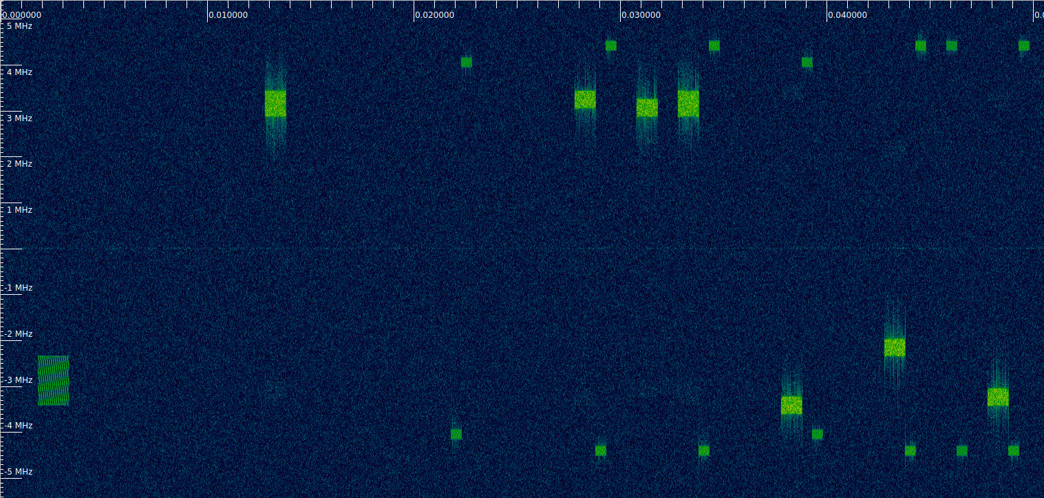
An alternative way of finding the radio frame synchronization is to take advantage of the fact that the recording contains a PRACH transmission. The waterfall below shows the beginning of this recording. The PRACH transmission is the first transmission, starting at about 2 ms from the beginning. The first PUSCH transmission starts exactly 20 ms afterwards.
If we have the SIB2 for this cell, then we know in which subframe the PRACH transmissions must happen. In my PDSCH post I decoded the SIB for cell 380, which is a neighbour cell to 378 (there are three cells on the same site, each illuminating a 120 degree angle). The recording of the downlink of cell 380 was made a few months after this recording of the uplink. If we assume that the two cells use the same PRACH configuration and that it hasn’t changed in that period of time, we can use the information in that post. In the SIB2, there is radioResourceConfigCommon, which contains prachConfig, which contains a prach-ConfigIndex. The value of this field is 19. This index corresponds to an entry in Table 5.7.1-2 in TS 36.211, which is reproduced here for convenience.
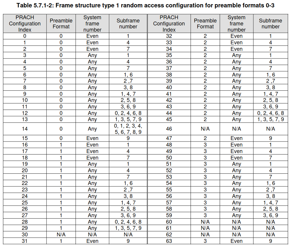
Index 19 means that the PRACH can be transmitted in subframe 1 of every radio frame. This is consistent with what we found using the PUCCH \(r_u^\alpha(n)\) sequences. Note that there are some PRACH configurations in which PRACH can be transmitted in multiple subframes, so in these cases using the timing of the PRACH wouldn’t serve to find the radio frame synchronization unambiguously.
Finding the C-RNTI with a PUSCH transmission
Above, I have explained how to reduce the set of C-RNTI candidates to just 64 by using the scrambling sequence of PUCCH format 2, 2a, and 2b transmissions. To decode the PUSCH, we need to narrow this down to a single C-RNTI. We will do this by using one PUSCH transmission. We are relatively lucky that this recording contains a PRACH transmission. What happens after the PRACH is usually quite predictable (see this post). The eNB replies with a RAR that assigns a temporary C-RNTI, and the UE sends a PUSCH transmission with an RRCConnectionRequest message in the CCCH (common configuration channel) by using this temporary C-RNTI, which later on becomes the UE C-RNTI. We can see this first PUSCH transmission in the waterfall above, at approximately 13 ms from the beginning.
The contents of the RRCConnectionRequest message are not predictable, because they contain the the UE TMSI. However, the length of this MAC PDU is always 7 bytes. Therefore, assuming that the UE is granted a transport block of exactly the length needed to transmit this MAC PDU (which I’m not sure of, but I think is always the case), then we know that the transport block size for this transmission is 56 bits.
Looking at the waterfall, we see that the first PUSCH transmission occupies 3 resource blocks. The transport block size is determined by the number of occupied resource blocks \(N_{\mathrm{PRB}}\) and an index \(I_{\mathrm{TBS}}\), which is obtained from the MCS and determines the coding rate. This information is in Table 7.1.7.2.1-1 in TS 36.213. The beginning of that table is shown here.
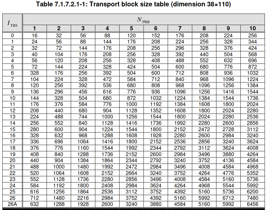
We see that for 3 resource blocks, a transport block size of 56 bits corresponds to \(I_{\mathrm{TBS}} = 0\), which is the lowest possible coding rate. It would make sense that for replying to PRACH with an RRCConnectionRequest message, the uplink grant is always 3 resource blocks with the lowest possible coding rate (MCS 0, which gives \(I_{\mathrm{TBS}} = 0\)). This would maximize the chances of the eNB decoding the message, since at this moment the eNB doesn’t know how much link margin the UE has (it has only received its PRACH). I don’t know if this is a general rule, though.
In any case, this first PUSCH transmission is good to find the C-RNTI because we have strong confidence that the transport block size is 56 bits. This is also advantageous because the low coding rate means that the rate matching algorithm will repeat the Turbo codeword bits multiple times. These repeated bits will only match if the correct C-RNTI has been used when computing the scrambling sequence.
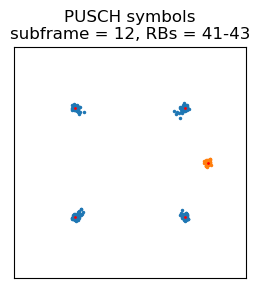
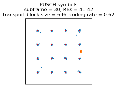
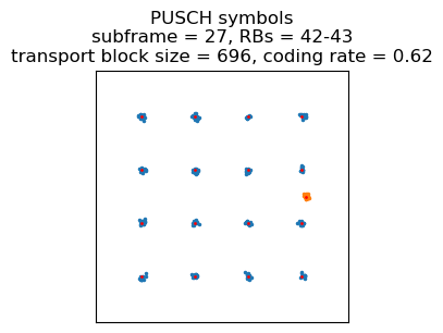
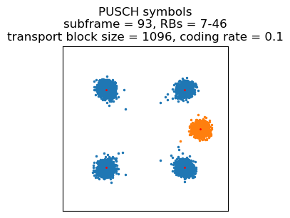
I already explained how to demodulate the PUSCH in my first post about LTE. Here is the constellation for this first PUSCH transmission. The DMRS is shown in orange (its spreading sequence has been wiped off), and the data symbols are shown in blue.
Something that is different in the PUSCH compared to the PDSCH is that there is a channel interleaver step that is done with the rate matched data before scrambling. In the PDSCH, the rate matched data is mapped in lexicographic order of time and frequency, so adjacent symbols will be transmitted at the same time on adjacent subcarriers. In the PUSCH, the symbols are interleaved by writing them by rows in a matrix with 12 columns (12 is the number of data time-domain symbols in a PUSCH transmission, since 2 time-domain symbols are used for the DMRS). The symbols are then read by columns before scrambling. Note that here I’m saying symbols rather than bits. A symbol is a group of 2 adjacent bits for QPSK, or 4 for 16QAM, etc. The result of this interleaver is that symbols that are adjacent after rate matching, end up being mapped to different time-domain symbols, which gives some resistence against burst errors.
To find the C-RNTI, we take each of the 64 candidate C-RNTIs, calculate the corresponding scrambling sequence by using the initialization value\[n_{\mathrm{RNTI}}\cdot 2^{14} + q\cdot 2^{13} + \lfloor n_s / 2 \rfloor \cdot 2^9 + N_{\mathrm{ID}}^{\mathrm{cell}}\](here \(q\) denotes the codeword number, so \(q = 0\) for a single-codeword transmission), descramble the data symbols using this sequence, deinterleave, and undo the rate matching algorithm assuming a transport block size of 56 bits and redundancy version index 0 (which must be the case: since this is the first transmission, it cannot be a HARQ retransmission). Since the transmission uses a low coding rate, each Turbo codeword bit is repeated multiple times by the rate matching algorithm. By undoing the rate matching algorithm, we group together each of these repetitions. Now we check if all the symbols in each group have the same sign, which should be the case if we have used the correct RNTI. In this case, this test singles out just one RNTI from the set of 64 candidates: the RNTI 0xbe52.
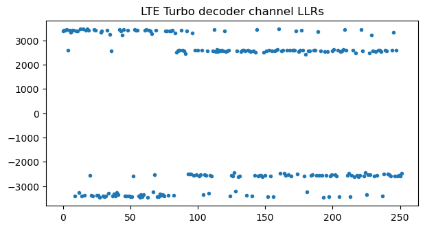
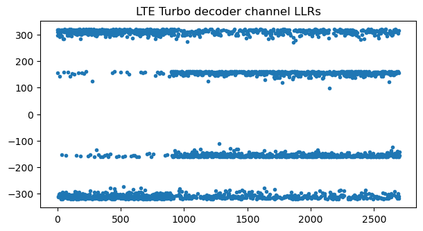
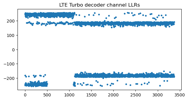
Now that we know the C-RNTI, we can attempt to decode this transport block. The coding of PUSCH transport blocks follows the same steps as for the PDSCH (except for the multiplexing of data and control information used in the PUSCH, which we will treat later). Therefore, the same procedures and code as in the PDSCH post can be used (in addition to the deinterleaving mentioned above). This figure shows the channel LLRs for the turbo decoder after soft combining of the rate matching repetitions. There are two distinct amplitude levels because, with a coding rate around 0.1, most of the bits in the information part of the Turbo codeword and some of the parity bits are repeated 4 times, while the rest of the bits are repeated 3 times. This plot also validates that the RNTI and transport block size are correct, since otherwise typically there would be cancellation during soft combining.
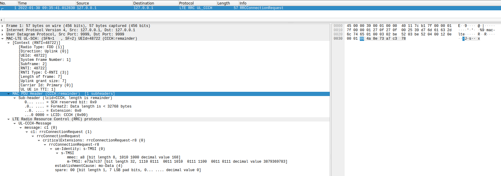
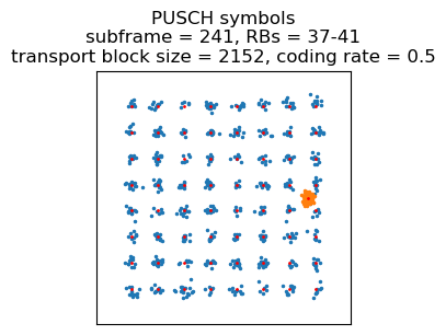
Turbo decoding of this codeword is successful, giving a transport block with correct CRC-24. When the transport block is dissected with Wireshark, we see that it is an RRCConnectionRequest message as expected.
Multiplexing of data and control information in the PUSCH
The same approach as for the first PUSCH transmission can be used to decode many of the other PUSCH transmissions in the recording. We need to know the transport block size and the redundancy version index. If the uplink quality is good, most often the redundancy version index will be 0, since no retransmissions are needed. If there is a retransmission, other redundancy versions can be tried (there are only 4 possible redundancy version values). To guess the transport block size, we first measure the number of occupied resource blocks in the waterfall. The possible transport block sizes are then given by the values in a column of Table 7.1.7.2.1-1 in TS 36.213. To reduce the number of possibilities to check, we use the fact that there is an interdependence between the MCS, the modulation, and the \(I_{\mathrm{TBS}}\) index. There are several tables for this depending on the configuration, but as a first guess we can use Table 8.6.1-1 in TS 36.213, which is shown here.
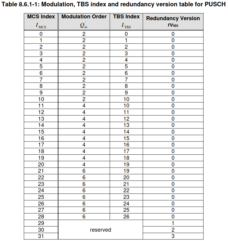
By looking at the constellation plot, we find the modulation order, and this restrics the range of possible \(I_{\mathrm{TBS}}\) values. In this recording, there is QPSK, 16QAM and 64QAM.
However, this approach will fail to decode some of the PUSCH transmissions. The reason is that, unlike for the PDSCH, the PUSCH can multiplex data and control information. Generally, a UE doesn’t transmit PUSCH and PUCCH at the same time (although newer LTE releases allow this). If the UE has some control information to transmit in the PUCCH during a PUSCH transmission, that control information is instead multiplexed with the PUSCH data. The details for this are described in Section 5.2.2 in TS 36.212, and are somewhat tricky to follow. The channel coding of control information is quite complicated, and even determining the the number of bits to encode the control information requires some formulas that depend on parameters \(\beta^{\mathrm{PUSCH}}_{\mathrm{offset}}\) that we don’t have.
The following figure, taken from the book LTE Advanced by Sassan Ahmadi, tries to summarize how the multiplexing works. The details are in Sections 5.2.2.7 and 5.2.2.8 of TS 36.212. The data symbols are the ones that are marked in white with no text. The first row of the figure corresponds to the subcarrier of lowest frequency (after SC-FDMA DFT precoding, that is). The figure shows a PUSCH transmission that occupies one resource block. A PUSCH transmission that occupies more resource blocks would be similar, with the CQI in the subcarriers of lowest frequency (rather than the same pattern being repeated in each resource block), and the RI and A/N in the subcarriers of highest frequency. As in the channel interleaving algorithm mentioned above, each entry in this table represents a symbol (2 bits for QPSK, 4 bits for 16QAM, etc.). In fact, the algorithm I explained previously is the particular case in which there is no control information.
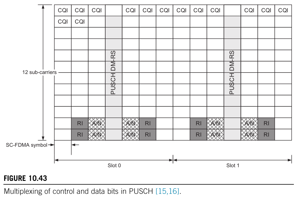
The way in which this matrix is filled for multiplexing of control and data information is important. First, the CQI information (if any) is written by rows starting at the beginning of the table. Then the rank information, RI, (if any) is written by rows starting at the last row of the table and going up, and using only the columns shown in the figure. Then the PUSCH data is written by rows starting at the first vacant entry (which is either the first of the table if there is no CQI, or the position where the CQI ended), and continuing going down until all the vacant entries of the table are filled (so the size of the rate-matching output is equal to the total number of entries in the table minus the ones occupied by the CQI and RI). Finally, the HARQ ACK/NACK information, A/N, (if any) is punctured into the PUSCH data. Entries previously assigned to PUSCH data are overwritten with HARQ ACK/NACK starting by the last row of the table, using only the columns shown in the figure, and continuing upwards. Finally, the symbols are read by columns before scrambling.
In our case, we don’t know whether each of these types of control information is present, and their lengths. Knowing this is necessary to demultiplex the data and control information correctly. Thinking about how this multiplexing interacts with the rate-matching and Turbo decoding for the PUSCH data, the first thing that we realize is that it’s necessary to know the length of the CQI and RI. Otherwise we will be undoing the rate-matching with a wrong size and/or passing incorrect data to the Turbo decoder, which will fail.
Since the ACK/NACK information overwrites the PUSCH data, we might get away with ignoring that there is ACK/NACK if the Turbo decoder can correct these bit errors. However, I have found that since in this case the SNR is high and I’m using a relatively low noise sigma for the Turbo decoder, sometimes enough of these bit errors prevent it from decoding correctly (which makes sense, because the bit errors have very high LLRs). What we can do is to puncture the ACK/NACK symbols by replacing them by zeros. We don’t need to know the exact size of the ACK/NACK data. We can puncture more than the actual size of ACK/NACK. This will result in some erasures that the Turbo decoder can correct. Once we get a successful decode, we re-encode the transport block, and compare it with the received data. In this way we can check for mismatches between the received an re-encoded data, and get a better estimate of the actual size of the ACK/NACK data (not necessarily the correct one, since some of the ACK/NACK bits can coincide with the data bits that they overwrite).
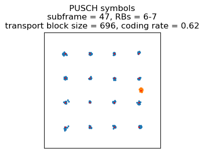
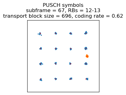
The first example of a PUSCH transmission that has multiplexed HARQ ACK/NACK data is the third transmission in the recording. This is a 16QAM transmission, and its constellation plot is shown here.
Let us first ignore that there is HARQ ACK/NACK. The following shows the channel LLRs passed to the Turbo decoder. There are two different amplitude levels because in 16QAM half of the bits have better protection than the other half. There are also many zeros because with a coding rate of 0.62, which is greater than 0.33, only the information bits (except a few which are punctured) and some of the parity bits are sent. Note that with a coding rate higher than 0.33, the rate-matching doesn’t repeat any bits. Therefore, we can’t check for consistency after undoing rate-matching to see if we’re decoding with the correct parameters.
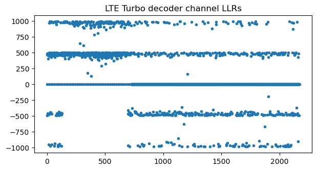
Something interesting to note in the LLRs is that there is a large segment of the LLRs for the message bits which are all positive (or zero, if they have been punctured). This is because this transport block contains a lot of zeros for padding at the end. Usually, uplink grants are for a transport block much larger than the data that the UE has to transmit, since the eNB doesn’t know exactly how much data the UE has. In this case, the MAC PDU is padded with zeros at the end to fill the transport block. In this recording, unless the UE has a large PDCP PDU to transmit, which gets split into several PUSCH transmissions in consecutive subframes, the MAC PDUs have lots of zeros at the end, which can also help us figure out the correct decoding parameters.
Turbo decoding is successful even though we have ignored that there are HARQ ACK/NACK bits. However, we can re-encode the decoded transport block and compare it with the received data. The following plot shows a 1 for symbols at the output of the Turbo encoder that match, and a 0 for symbols that don’t match. We see that there are a few mismatches. These correspond to symbols that have been overwritten by HARQ ACK/NACK data.
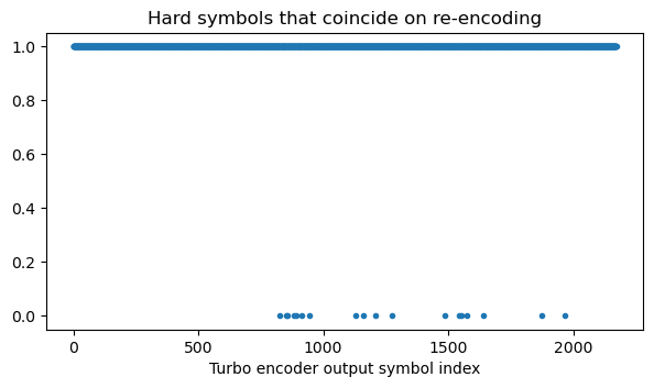
We can now increase one by one the number of symbols that we consider as punctured by HARQ ACK/NACK and make this plot again. With 6 HARQ ACK/NACK symbols, there are only two bits in mismatch.
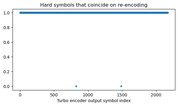
With 7 HARQ ACK/NACK symbols, everything matches. This doesn’t mean that the size of the HARQ ACK/NACK data is necessarily 7 16QAM symbols (28 bits). It might happen that it is slightly longer and the end of the data coincides with the PUSCH data that it has overwritten.
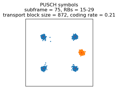
The first PUSCH transmission that multiplexes CQI information appears in subframe 78. Indeed, looking at the subframes in which PUCCH format 2, 2a, or 2b is transmitted, we see that there is such a transmission in every subframe congruent with 3 modulo 5, unless there is a PUCCH format 1, 1a, 1b or PUSCH transmission on that subframe. This most likely means that the UE has been configured to report CQI every 5 ms. Therefore, we can expect to have multiplexed CQI data in each PUSCH transmission that happens on a subframe congruent with 3 modulo 5. The length of the encoded CQI data will generally be different for each transmission, since the encoding length depends on the MCS of the transmission.
This PUSCH transmission in subframe 78 uses QPSK and a coding rate of 0.21. This is helpful, because it means that the rate-matching algorithm repeats some bits.
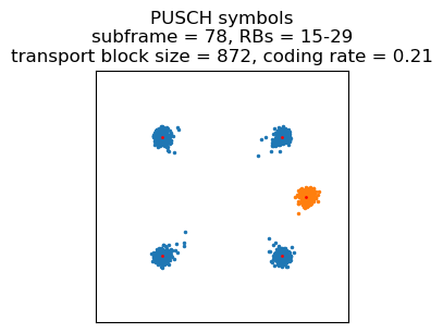
If we ignore the fact that there is multiplexed CQI data, the channel LLRs passed to the Turbo decoder look like this for the correct transport block size of 872 bits. The two amplitude levels correspond to bits that are repeated either twice or only once by the rate matching. The LLRs around zero correspond to bits that are repeated twice and have cancellation because we are ignoring the CQI data.
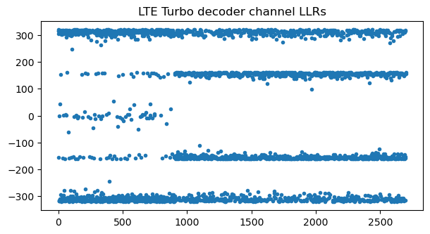
A different way to look at this cancellation is to plot the groups after undoing rate-matching that have all the LLRs in the group with the same sign (a 1 in the plot below) versus those groups that have mismatching signs (a 0 in the plot below). We see that there are some mismatches in the first part of the message. Using a wrong transport block size causes even more mismatches, so we can typically find the correct transport block size even if we don’t know the number of CQI symbols.
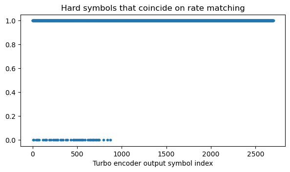
To find the number of CQI symbols, we keep increasing this value until there are no mismatches for rate matching and decoding is successful. Unlike for HARQ data, this strategy will really give us the exact number of CQI symbols, because the CRC-24 check can’t possibly work if we’re including some CQI bits as part of the transport block. In this case, the number of CQI symbols is 51 (102 bits), which gives the following channel LLRs and a correct decode.
These strategies can be used to find the correct number of CQI bits and HARQ ACK/NACK bits for the PUSCH transmissions that multiplex data and control. The same could be done with RI bits, but in this recording it seems that rank information is not sent (which makes sense, because I believe the UE only has one antenna port).
Summary of the PUSCH transmissions in the recording
This is just a summary of the most interesting aspects of the PUSCH transmissions in this recording. For more details and individual plots for each transmission, refer to the Jupyter notebook and the PCAP file.
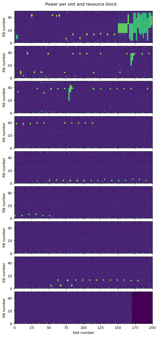
The following plot shows the power in each slot and resource block. Each row of the plot is 100 ms long. The PUCCH transmissions can be seen in the outermost edges of the cell. The PRACH transmission is the first one. The remaining transmissions are PUSCH. We see some narrow transmissions (narrow in the sense that they use few resource blocks) at the beginning. Then there is a series of wide transmissions at the end of the first row. There are more sporadic narrow transmissions, and two moments with transmissions of medium bandwidth in the second and third row. There are also some long gaps without any PUSCH transmissions.
The first PUSCH transmission is the RRCConnectionRequest message that we have used to find the C-RNTI. The next transmission already uses 16QAM and a coding rate of 0.62, so by then the eNB has already realized that the uplink SNR is good enough for a high MCS. This transmission doesn’t contain any data. It only has a long BSR (buffer status report) indicating that the buffers are empty and a PHR (power headroom report).
The next transmission is the one I have used as an example of multiplexed HARQ ACK/NACK. It contains an SRB 1 UL-DCCH message of type RRC connection setup complete with a NAS service request message. The service request message has the same form that we saw in the case of an UE reconnection in the Wireshark analysis of an srsRAN_4G eNB and UE. I don’t remember what I did with my phone for this recording. Perhaps I just disconnected from WiFi to get it to connect to the internet by LTE, in which case it’s expected that this is a network reconnection rather than an initial attach.
The HARQ ACK/NACK multiplexed in this transmission must be an ACK to the RRC connection setup message from the eNB. That message is transmitted in the CCCH, which doesn’t use RLC, so there is no AM ACK for the message.
The next 3 PUSCH tranmissions are long BSR reports indicating empty buffers. The first of them uses QPSK with a coding rate of 0.23, but the other two use 16QAM with a coding rate of 0.62.
The next transmission is a 16QAM transmission that only contains an AM ACK with sequence number 1 in SRB 1, and a short BSR indicating an empty buffer. We can imagine that this ACK is for a Security Mode Command message that the eNB has just sent in SRB 1. This would be the first message sent by the eNB is SRB 1. This PUSCH transmission doesn’t multiplex any HARQ ACK/NACK, so the HARQ ACK for the Security Mode Command must have been sent earlier in the PUCCH.
The next transmission is a similar 16QAM transmission that contains a Security Mode Complete in SRB 1. After this point, all the control information is encrypted, so we can’t analyze it. Next, there is a transmission that only contains a long BSR indicating empty buffers. It seems that whenever the UE doesn’t have anything to send, it sends such a long BSR every 5 ms, except during the periods when there are no PUSCH transmissions at all. Probably this means that the UE is being regularly scheduled uplink every 5 ms just in case it has some new data.
The next transmission is a 16QAM transmission containing an AM ACK with sequence number 2 in SRB 1. If the reconnection process follows the same kind of exchange that we saw with srsRAN, this ACK would be for a UE Capability Enquiry message sent by the eNB.
After this, the UE transmits a couple more times following its usual 5 ms scheduling cadence. These are also 16QAM transmissions, but they are interesting because they contain the first two fragments of a much larger PDCP PDU. The UE is beginning to send a UE Capability Information message. These messages can be quite large for real-world UEs (unlike the srsRAN UE, which is somewhat simplified). The first of these transmissions contains a short BSR indicating that the buffer size is between 1818 and 2127 bytes, so there is still a lot of data to send.
After these two transmissions, the series of wide transmissions begins. The eNB has realized that the UE has a lot of data to send, and it schedules the UE to transmit every subframe with a much wider resource block allocation. These transmissions are all QPSK, with a transport block size of ranging between 872 and 1096 bits (coding rate between 0.1 and 0.21) . This represents only a small transport block size increase over the earlier 16QAM transmissions that occuppy only 2 resource blocks. The reason is that, judging by the PHR sent in the second transmission (sent in a 16QAM transmission using 2 resource blocks), the UE doesn’t have any more power to scale the transmit power up with increasing bandwidth (the PHR indicated a headroom between -2 and -1 dB). So when the eNB needs the UE to transmit more data, the only option it has is to give it a much wider allocation and switch to QPSK and a much lower coding rate. This is more efficient in terms of Eb/N0 and allows the UE to send somewhat more data with the same power, at the cost of a large bandwidth increase.
In the waterfall it is apparent that the power spectral density of these transmissions has decreased, because the UE has increased the bandwidth but maintained the same power. This can also be seen in the constellation, which is much noisier.
These transmissions are representative of the maximum uplink rate for the UE in these conditions (indoor near a window, with the eNB a few blocks away and not in line of sight from the window, and in the B20 band at 800 MHz). The data rate that can be achieved is around 1 Mbps, since the transport block size can go slightly above 1000, and a transport block can be sent every millisecond.
The widest of these transmissions occupies 40 resource blocks. We know that at least 3 resource blocks on each edge of the cell are dedicated to the PUCCH. Therefore, 40 resource blocks is the widest possible PUSCH in this 50 resource block 10 MHz cell, because there are 44 resource blocks in the region that is usable by the PUSCH, but the number of resource blocks in a PUSCH allocation can only have 2, 3 and 5 as prime factors, due to the need of applying DFT precoding.
Incidentally this is also the PUSCH transmission in which the UE finishes sending the large PDCP PDU. This can be seen in the LLRs, by the presence of a region which corresponds to zero padding at the end of the transport block.
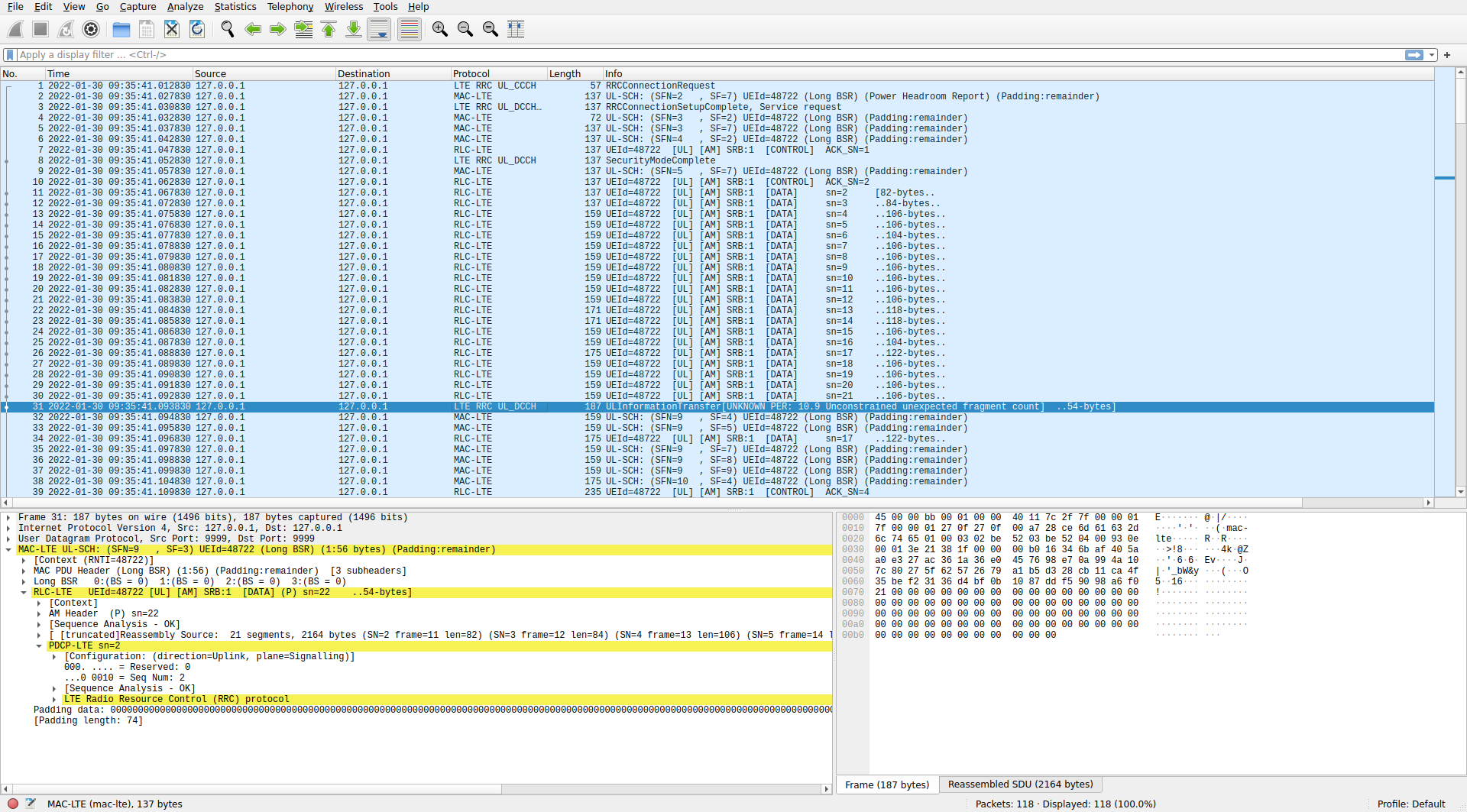
The following Wireshark screenshot shows how the UE Capability Information message has been transmitted. It is a PDCP message with sequence number 2 in SRB 1 (ignore the Wireshark dissection as an ULInformationTransfer message, which is caused by Wireshark treating this message as unencrypted because it hasn’t seen the Security Mode Command message from the eNB that turns encryption on). The PDCP PDU has 2164 bytes and is transmitted in 21 fragments that carry between 104 and 122 bytes of data (except for the first two fragments, which still use narrowband 16QAM transmissions that carry around 84 bytes of data).
After finishing to send the UE Capability Information message, the UE continues sending consecutive wideband QPSK PUSCH transmissions for 6 more subframes. All of these don’t carry any data (just a long BSR indicating empty buffers) except for this transmission on subframe 96, which is a retransmission of the transmission on subframe 88 (8 subframes earlier). The retransmission uses redundancy version index 2, which the most common choice for a first retransmission after the original transmission (which uses redundancy version index 0).
Note that, besides the last transmission, which used a transport block size of 1096 bits, this transmission is the one with a largest transport block size (1000 bits). Therefore, the fact that the eNB needed a retransmission indicates that around 1000 bits is the maximum that these uplink conditions can support.
As mentioned above, in the PUSCH transmissions that appear in a subframe congruent with 3 modulo, CQI is interleaved with the data. Since in this part of the recording there are back-to-back PUSCH transmissions, this happens a few times: in subframe 78 there are 102 bits of CQI, in subframe 83 interestingly there isn’t CQI, in subframe 88 there are 284 bits of CQI, in subframe 93 there are 288 bits of CQI, in subframe 98 there are 216 bits of CQI. There are no subframes with HARQ ACK/NACK data, which is reasonable because the eNB is simply waiting to receive the UE Capability Information message before sending more data.
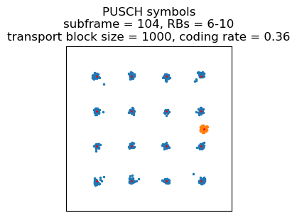
After subframe 99, the UE stops transmitting data every subframe. The next PUSCH transmission occurs 5 subframes afterwards, in subframe 104. It is a 16QAM transmission with 4 resource blocks. It only contains a long BSR indicating empty buffers. The eNB has rescheduled the UE every 5 subframes using a narrow 16QAM allocation, but this time the transport block size is somewhat larger than before (before, 16QAM allocations used 3 resource blocks and a transport block size around 700 bits).
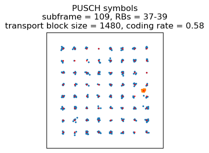
The next transmission is 5 ms later, and it is a 64QAM transmission occupying 3 resource blocks with a transport block size of 1480 bits. It appears that now the uplink link budget has improved. This transmission only contains an AM ACK with sequence number 4 in SRB 1. The last AM ACK that we saw had sequence number 2. I don’t know what two AM PDUs the eNB has sent in the mean time. One of these is probably an RRC Connection Reconfiguration sent after the UE capabilities (this message would enable SRB 2 and DRB 3). Perhaps the message was fragmented into two AM PDUs.
After 5 ms, the UE transmits 64QAM in 2 resource blocks (transport block size 1128). The transmission carries a PDCP PDU with sequence number 3 in SRB 1. This would contain an RRC Connection Reconfiguration Complete message, but the PDU is encrypted. Interestingly, Wireshark manages to dissect the payload half correctly as rrcConnectionReconfigurationComplete (although it gives nonsensical criticalExtensions), but I think this is just sheer luck, because Wireshark is trying to dissect the encrypted data without decrypting it.
In subframe 119, 5 ms later, there is a similar 64QAM transmission. This contains a PDCP PDU in DRB 3 (which uses the AM RLC protocol) with 57 bytes of payload. This is a reasonable size for a small IP packet, perhaps a DNS query.
The next transmission, in subframe 124, is another 64QAM transmission in 2 resource blocks that contains an AM ACK in SRB 1 with sequence number 7. This means that the eNB has sent some additional control information to the UE. In subframe 136, the 64QAM transmission now occupies a single resource block. It contains an AM PDU in SRB 1 that carries two short PDCP PDUs. It also carries a PHR indicating that the headroom is between 4 and 5 dB. In subframe 142 there is a 64QAM transmission that uses 2 resource blocks. It contains an AM ACK in DRB 3 with sequence number 2. It looks like the reply for the IP packet previously sent by the UE has arrived and now the UE is sending the AM ACK.
The next 4 transmissions are in subframes 147, 152, 157 and 162. They only contains a long BSR indicating empty buffers. All of them are 64QAM in 2 resource blocks, often with a transport block size of 1128 bits (coding rate 0.7).
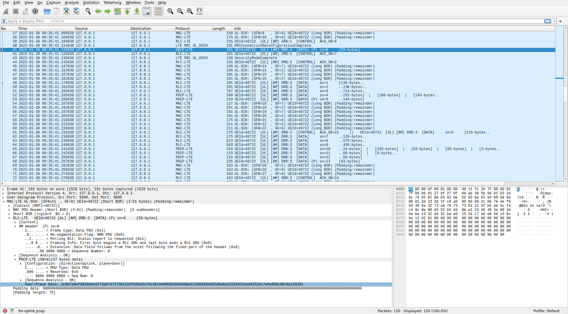
In subframe 176, the UE starts transmitting a long PDCP PDU in DRB 3. The size of the PDCP PDU payload is 1278 bytes, which could be the IP MTU. The transmission of this PDU works similarly to the long UE Capability Information PDU that we saw before. The transmission starts in 64QAM in 2 resource blocks and the UE reports in a short BSR that it still has more data. After 5 ms, there is another similar transmission. In subframe 184, the UE is rescheduled to transmit 16QAM in 20 resource blocks. This achieves a transport block size of 5736 bits, which is much larger than anything we have previously seen.
In the next subframe the UE is only given 12 resource blocks, for a transport block size of 4392 bits. This finishes the long PDCP PDU. The transmission also contains a full DRB 3 PDCP PDU with a payload of 106 bytes, and the beginning of another DRB 3 PDCP PDU. This PDU is finished in the next subframe, which is 64QAM in 4 resource blocks, with a transport block size of 2152 bits. The PDCP PDU has 285 bytes of payload.
After this, the UE transmits PUSCH containing just a long BSR indicating empty buffers in subframes 187, 192, 197, 202, 216, 221, and 226. These are all 64QAM using few resource blocks, except for the transmissions in subframes 221 and 226, which are 16QAM in 3 resource blocks (transport block size 1288) that have multiplexed approximately 11 bits of HARQ ACK/NACK.
In subframe 231 the UE starts transmitting a large amount of data again. The PUSCH in that subframe is a 64QAM transmission in 2 resource blocks. It contains a DRB 3 AM ACK with sequence number 22. The previous ACK we saw in DRB 3 had sequence number 2, so we infer that the network has sent some large IP packets to the UE. The transmission also contains the beginning of a PDCP PDU that has a 1278 byte payload. As usual, a short BSR control element informs to the eNB that there is much more data to send. The next transmission is a similar 2 resource block 64QAM transmission in subframe 236. It carries a segment of the large PDCP PDU.
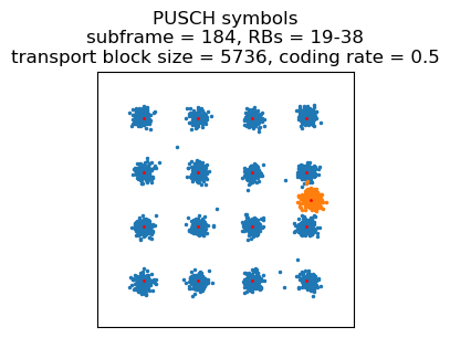
The UE is reallocated to a wide 16QAM transmission in subframe 239, for a transport block size of 4584 bits using 20 resource blocks. This has another segment of the large PDCP PDU.
A similar 16QAM transmission but occupying only 10 resource blocks for a transport block size of 3624 bits happens in the next subframe. This contains a fragment of the large PDCP PDU.
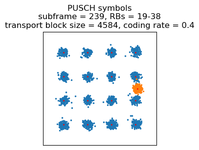
In the following subframe, the modulation is again 64QAM, using only using 5 resource blocks, which gives a transport block size of 2152 bits. This carries the last segment of the large PDCP PDU, another full PDCP PDU with 101 bytes of payload, another with 61 bytes of payload, another with 65 bytes of payload, and the beginning of another PDCP PDU with 61 bytes of payload that will be completed in the next transmission.
In the next subframe (242) the modulation is again 64QAM, but using only one resource block (transport block size 552 bits). This contains the end of the 61-byte PDCP PDU, and the beginning of another PDCP PDU with 61-byte payload. The end of that PDU only comes in subframe 256, with another 64QAM transmission in a single resource block. The next subframe has a 3 resource block 64QAM transmission that contains another 61-byte payload PDCP PDU. It also contains a long BSR informing that the buffers are now empty.
Subframes 262, 269 and 274 are 2 resouce blocks 64QAM transmissions that contain only a long BSR indicating empty buffers. Subframe 279 has a DRB 3 AM ACK with sequence number 24. From this we infer that some IP packets have arrived to the UE in reply to the packets that it sent some subframes ago. Subframe 284 has only a long BSR. Subframe 296 contains another 61-byte PDCP PDU in DRB 3.
The next transmissions happen every 5 subframes, except for a gap. They appear in subframes 301, 306, 311, 316, 321, 336, 341, 346, 351, 356. They contain a long BSR indicating empty buffers. In addition, the transmission in subframe 336 contains a power headroom report. All these transmissions use 2 resource blocks, and all are modulated with 64QAM except for subframe 306, which is 16QAM.
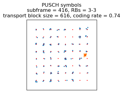
There is a gap without transmissions until subframe 416, which has a 64QAM transmission in a single resource block that contains a PDCP PDU in SRB 1 with sequence number 6.
Next there are 20 tranmissions every 5 subframes, spanning subframes 425 to 525. Most of these contain a long BSR indicating empty buffers. The others contain a PDCP PDU in SRB 1 and/or an AM ACK in SRB 1. So during this time there is some control traffic exchanged between the UE and the eNB. All of these occupy 2 resource blocks. They use 64QAM until subframe 490, and 16QAM after it.
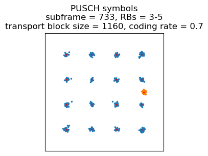
After this, there is a long gap without tranmissions, ending with a power headroom report in subframe 726. The next transmission is an AM ACK and a PDCP PDU in SRB 1. The remaining tranmissions only have a long BSR indicating empty buffers. These happen in subframe 733, 738, and in subframes 744-789 every 5 subframes. All of these use 16QAM and either 2 or 3 resource blocks.
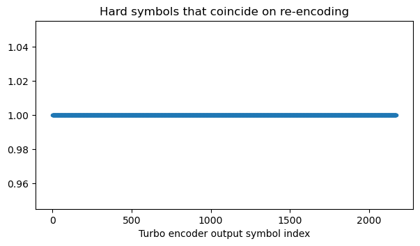
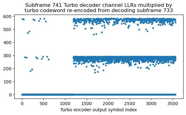
In subframe 741 there is an interesting transmission. After some trial and error to decode it, this turns out to be a retransmission of subframe 733 (8 subframes of difference, as expected). The retransmission uses redundancy version index 2, but the coding rate is high enough that it is not possible to decode it using only this redundancy version.
To check that this description is correct, we obtain the channel LLRs for the Turbo decoder from subframe 741. We then re-encode the Turbo codeword in subframe 733 and multiply it by the channel LLRs for subframe 741. Wherever the bits coincide the result will be positive (or zero if the bit was punctured). The plot below shows the result. Since there are no negative values, this verifies the conclusion.
Conclusions
In this post we have seen how decoding the PUSCH is more challenging than decoding the PDSCH, because the parameters for each transmission need to be guessed. Nevertheless, using the ideas given here it is possible to decode PUSCH transmissions of a recording of only the uplink signal if the SNR is good.
Looking at the resource block allocations and modulation used in these transmissions, we have seen how the eNB scales the transmit bandwidth available to the UE according to the data that it has pending in its transmit buffers. Whenever possible, a high order modulation such as 64QAM and a high coding rate are used to save bandwidth, but when necessary the modulation can drop to a low coding rate QPSK over a large bandwidth allocation, because that is more efficient in terms of Eb/N0.
Code and data
Since in this post I’m using both the PUSCH and the PUCCH, I have combined the separate Jupyter notebooks that I wrote in my PUSCH demodulation and PUCCH demodulation posts into a single LTE uplink notebook, which I have extended with all the work for this post. Since there is a lot of common code used for the uplink and the downlink, I have extracted this into an lte.py file, which is imported in this notebook (I haven’t updated the downlink notebook yet to use this file). The PCAP file containing the decoded frames can be found here. The SigMF recording is here.