LTE downlink: synchronization signals

I have been posting about analysing LTE signals, with a focus on the structure of the pilot signals. I my two previous posts on this topic, I looked at the uplink using an IQ recording of my phone. Now I turn my attention to the downlink. I have done a short recording of the B20 band carrier of my local base station and I will be analysing it in this and future posts.

In this post, we will look at the primary synchronization signal (PSS) and secondary synchronization signal (SSS). These are the first signals in the downlink that a UE (phone) will attempt to detect and measure to estimate the carrier frequency offset, symbol time offset, start of the radio frames, cell identity, etc.

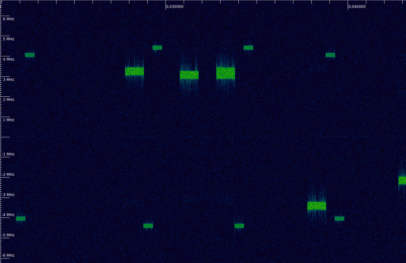
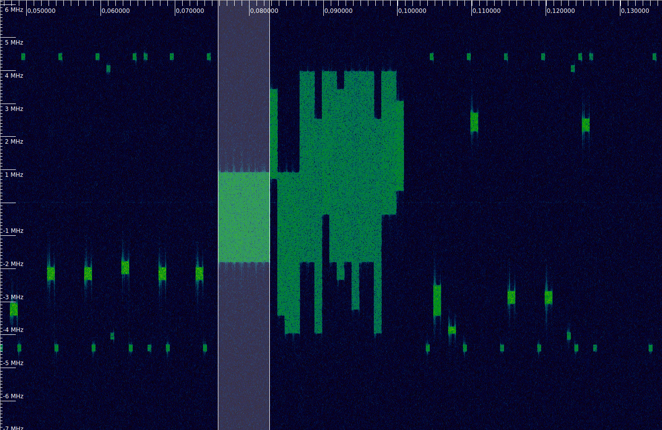
In an FDD system such as the one we are looking at here, the PSS is transmitted in the last symbol of slots 0 and 10 in each radio frame (Recall that LTE FDD signals are organized in 0.5 ms slots each containing 7 OFDM symbols. A radio frame lasts 10 ms and contains 20 slots). The SSS is transmitted on the symbol before the PSS.

The figure below shows the waterfall of the first 20 ms of the recording. I have marked the locations of the PSS and SSS with a red tick. These signals only occupy the 6 central resource blocks (1.08 MHz), so that they are compatible with all the possible cell bandwidths (LTE supports cell bandwidths of 1.4, 3, 5, 10, 15 and 20 MHz) and can be received by a UE which doesn’t know the cell bandwidth yet. In this case, we are looking at a 10 MHz cell, and we can see the neighbouring 10 MHz cells in the top and bottom of the waterfall.

Waterfall of LTE downlink carrier. Synchronization signals are marked with a red line.

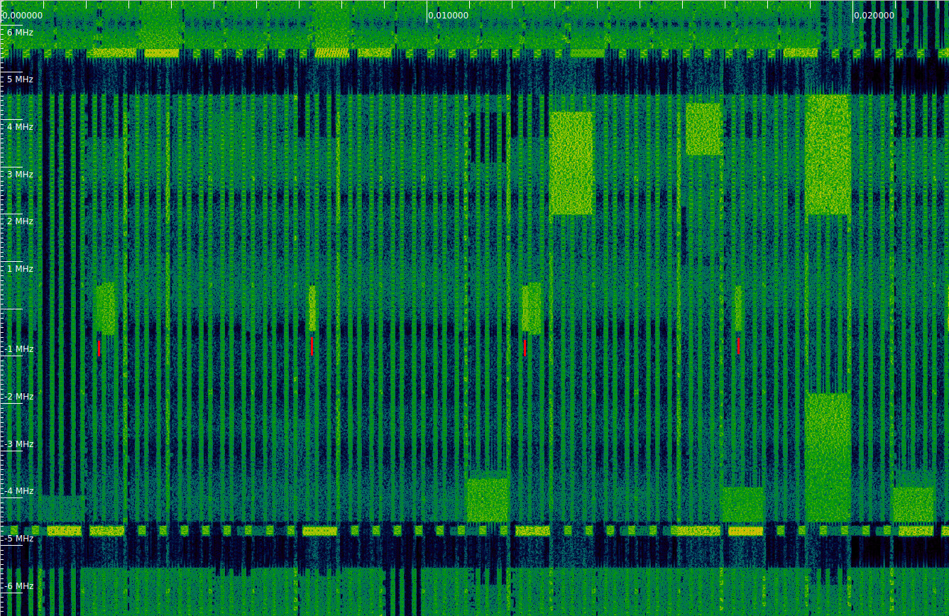
We can see that every other PSS and SSS transmission there is another 1.08 MHz transmission following it. This corresponds to the PBCH (physical broadcast channel), which is transmitted on the first 4 symbols of slot 1 in each radio frame. The keen reader will have noticed that the PBCH is slightly wider than the PSS and SSS. This is because the PSS and SSS only use the central 62 out of 72 subcarriers in the 6 resource blocks they occupy, leaving 5 subcarriers at each edge as a guardband. This helps UEs having a large carrier frequency offset to detect these signals. On the other hand, the PBCH occupies all the 72 subcarriers.

Demodulation of LTE PUCCH

In a previous post I showed how to demodulate the LTE physical uplink shared channel (PUSCH) by using a recording of my phone and some Python code. This is a continuation of that post. Here we will look at the physical uplink control channel (PUCCH) transmissions in that recording, and use a similar approach to demodulate them. All the work is done in a Jupyter notebook, which is linked at the end of the post.

The PUCCH carries control information from the UE to the eNodeB, such as scheduling requests, ACK/NACK for HARQ, and the CQI (channel quality indicator). A PUCCH transmission lasts for one subframe (1 ms) and typically occupies a single 12-subcarrier resource block in each of the two 0.5 ms slots in the subframe (there are more recently introduced PUCCH formats which use more subcarriers).

PUCCH transmissions are allocated to the edges of the uplink bandwidth, so as to leave the centre clear as a contiguous segment to be used for PUSCH. On its first slot, the PUCCH transmission uses some particular resource block. On its second slot it uses the symmetric resource block with respect to the centre frequency. This gives some frequency diversity to the transmissions.

The figure below shows a portion of the waterfall of the LTE uplink recording that we will be using (the link to the recording is included in the previous post). It corresponds to a 10MHz-wide cell in the B20 band. The PUCCH transmissions are the narrow bursts. The wider stronger bursts are PUSCH.

Waterfall of an LTE uplink showing some PUCCH and PUSCH transmissions

This illustrates that the PUCCH subframes are allocated to the edges of the cell, and how each subframe jumps to the symmetric resource block on its second slot.

Demodulation of the LTE uplink

I have been playing with some LTE recordings to brush up my knowledge, since it isn’t a protocol I’m very familiar with. I’m specially interested in understanding the structure and properties of all the pilot signals. Textbooks and documentation are great, but nothing beats getting your hands dirty with some IQ recordings to be sure you understand all the details.

To have something to work with, I have done some recordings of my phone by holding it near a USRP B205mini without an antenna. While recording, I was playing a Youtube video or browsing the web, to have some traffic. A waterfall of one of the recordings can be seen below. In this post we will be looking at how to demodulate the highlighted section, which contains 7 ms of PUSCH (physical uplink shared channel) occupying 15 resource blocks, together with the corresponding DMRS (demodulation reference signal) symbols. The post assumes some familiarity with OFDM, but doesn’t require any previous knowledge of LTE, so it can be useful to people interested in a hands-on introduction to LTE.

Waterfall of LTE uplink signal (using inspectrum)