Since some time, I’ve been thinking about doing something similar to my posts about LTE and 5G NR, but for WiFi (IEEE 802.11). In these posts, I take a signal recording and write a Jupyter notebook from scratch to analyze the signal and decode the data. I use these posts as a way of learning all the details of how these standards work, and I have seen that some people find them very useful.
Recently I was taking a look at a baby monitor camera system, composed by a camera and a monitor screen, since I was curious about how the camera transmits the video. Using Maia SDR, I located the signal at 866 MHz and realized that both the camera and the monitor screen were transmitting OFDM packets of approximately 2 MHz of bandwidth on this frequency. With some cyclostationary analysis, I found that the subcarrier spacing was 31.25 kHz (which works out to be 2 MHz / 64 FFT points), and that the cyclic prefix was 1/4 of the useful symbol duration. This pointed me straight to IEEE 802.11ah (WiFi HaLow), a variant of WiFi designed for the 800 MHz and 900 MHz license-exempt bands. After comparing the packet formats on the 802.11ah standard with the waterfall of my recording, I was sure that this was indeed 802.11ah. What started as a fun and short signal recording experiment has ended up going through the rabbit hole of implementing 802.11ah decoding from scratch in a Jupyter notebook. In this post I explain my implementation and the analysis of this recording.
In case anyone is curious about this baby monitor in question, its FCC ID is 2AG7C-BABY1M (I believe this applies only to the monitor screen. Other FCC IDs such as 2AG7C-BABY1S seem to cover the camera.) The FCC reports contain some interesting technical information, although I haven’t seen any reference to 802.11ah in them. Something to keep in mind is that the FCC reports are for the 905-925 MHz frequency band. In Europe, the 863-870 MHz band is used instead.
I recorded at a sample rate of 3.84 Msps, since that was appropriate for the signal bandwidth and I didn’t know anything about the OFDM parameters of the signal when I made the recording. For analysis, I have resampled this recording to 4 Msps using GNU Radio, since that gives 128 samples per useful symbol, and all the OFDM timings become integer numbers of samples.
The IEEE standards that I will be referring to in this post are 802.11ah-2016, which contains the additions related to the sub-1GHz (S1G) PHY and other features introduced in 802.11ah, and 802.11-2016, which is the base standard to which 802.11ah-2016 adds and modifies sections (802.11ah-2016 isn’t a standalone document, so it needs to be read together with 802.11-2016). I guess that newer versions of the 802.11 standard already contain the 802.11ah changes incorporated into the main document, and might be easier to read.
Frame formats
The figure below shows an Inspectrum waterfall of the first two frames in the recording I made. We can see that these use OFDM, and have a preamble that only uses some subcarriers, which is typical in OFDM frames to allow synchronization using the Schmidl & Cox algorithm. It looks like the DC subcarrier is not used, which is also common in many OFDM systems. In the first frame, some symbols after its beginning, we also see some spectral lines similar to the preamble. This doesn’t happen in the second frame.

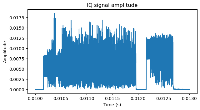
It is also apparent that the two frames are from different transmitters, since they have different powers and the second frame has significant distortion (there is a lot of spectral leakage). I don’t know if the cause of this distortion is receiver saturation or if it originates in the transmitter. I took care to reduce the gain of the Pluto SDR I used to record. The signal amplitude in the IQ data has a lot of headroom until full scale, as shown by the plot below, in which the amplitude is normalized to the 16-bit IQ full scale (amplitude 1 corresponds to full scale). So I suspect that the cause is the transmitter. Later we will also see more details that hint at these 802.11ah radios not being very good.
The S1G PHY defined in 802.11ah supports channel widths of 1 MHz, 2 MHz, 4 MHz, 8 MHz and 16 MHz. In this case, we are interested in the 2 MHz configuration, which is also the most basic configuration. It is based on clocking a regular 20 MHz WiFi OFDM configuration at 1/10 of the sample rate. It uses a 64-point FFT at 2 Msps, which gives 31.25 kHz of subcarrier spacing. The normal cyclic prefix (called guard interval in the 802.11 standards) is 1/4 of the useful symbol. This gives a symbol duration of 40 usec. A short cyclic prefix is also supported. This is 1/8 of the useful symbol, giving a symbol duration of 36 usec. The short cyclic prefix is only used in the data symbols of frames that have the short GI option enabled. The DC subcarrier is never used. Only 56 subcarriers (28 to each side of DC) out of the full set of 64 are occupied.
Section 23.3.2 in 802.11ah-2016 defines the PPDU (physical layer PDU) formats used by the S1G PHY. There are three formats: S1G_SHORT, S1G_LONG, and S1G_1M. We can ignore S1G_1M, because it is only used in 1 MHz channels.
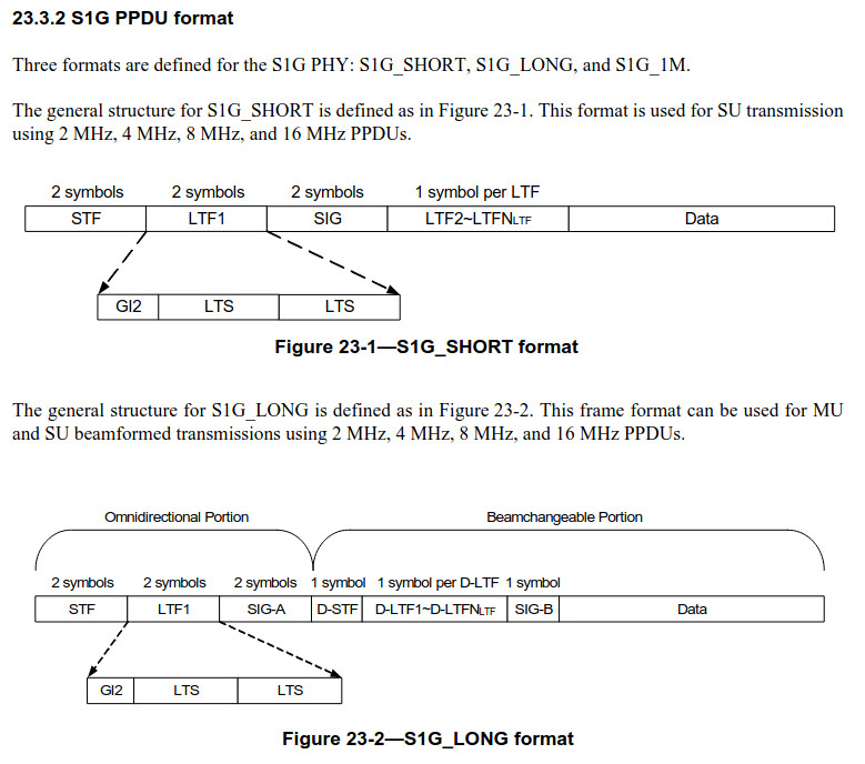
The difference between S1G_SHORT and S1G_LONG is that S1G_LONG supports beamforming, either for a single user (SU) or for multiple users users using MU-MIMO (MU). The 802.11ah S1G PHY borrows many techniques from the VHT PHY introduced in 802.11ac-2013 (WiFi 5). The VHT PHY introduced beamforming and downlink MU-MIMO, and these features are also available in the 802.11ah S1G PHY.
The two frame formats begin in the same way:
- Two symbols of STF (short training field). This only uses subcarrier indices that are a multiple of 4 (except for the DC subcarrier), and so it causes the spectral lines that we see at the beginning of the frames. The STF is mainly intended for frame detection and synchronization.
- Two symbols of LTF1 (long training field number 1). This occupies the full set of 56 subcarriers with pilot symbols. The LTF is mainly intended for channel estimation. A total of \(N_{STS}\) LTFs, where \(N_{STS}\) denotes the number of space-time stream, are required to jointly estimate the channels for all the space-time streams. In this recording, the stations use only one space-time stream, so only LTF1 will be used.
- Two symbols of SIG or SIG-A field. This is a physical header that describes the configuration of the data field of the PPDU (for instance the MCS and length). The format of the SIG and SIG-A fields is slightly different, but they are conceptually very similar. The SIG/SIG-A field only occupies the central 52 subcarriers. We can see this in the waterfall above. The SIG/SIG-A fields in the frames have a slightly narrower bandwidth.
After this initial part, the S1G_SHORT PPDUs contain the remaining LTF symbols (if any). In this recording, the two stations only use one space-time stream, so no LTF symbols appear at this point. Then the PPDU contains the data symbols, which also occupy the full set of 56 subcarriers.
The S1G_LONG PPDUs contain a beamchangeable portion, which is the part of the frame that can use beamforming. Due to this, the channel for this portion can be different from the channel for the omnidirectional portion at the beginning of the PPDU. Therefore, the beginning of the beamchangeable portion contains symbols which are intended for channel estimation of the beamformed channel. These are roughly the same as their omnidirectional counterparts at the beginning of the frame. They are:
- One D-STF symbol, which is roughly the same as the STF at the beginning of the frame. It causes the spectral lines that we see in the waterfall of the first frame a few symbols after the beginning of the frame. The D-STF field gives us a simple way to distinguish S1G_LONG and S1G_SHORT PPDUs in the waterfall. We can see that the first frame is S1G_LONG because it has this field, and the second frame is S1G_SHORT because it doesn’t.
- One D-LTF symbol for each space-time stream. This is roughly the same as the LTF symbols used in the S1G_SHORT PPDUs.
- One SIG-B symbol. In MU PPDUs, SIG-B contains additional data describing the MU transmission. In SU PPDUs, this data is not necessary, so the SIG-B symbol is a repetition of D-LTF1. In this recording, MU is not used, so SIG-B is always a repetition of D-LTF1.
The data is transmitted after these symbols.
Frame detection and coarse synchronization
The STF has some special properties that make it well suited for detection and synchronization using the Schmidl & Cox algorithm. It only uses subcarrier indices which are multiples of 4 (except the DC subcarrier, which is never used). This means that the time-domain OFDM symbol is \(T_u/4\)-periodic, where \(T_u\) denotes the useful symbol duration (32 usec). The STF is special regarding the guard interval in that it is defined to have no guard interval. This means that the useful symbol starts right at the beginning of the symbol. However, the symbol duration is still \(T_s = 40\, \mathrm{\mu s}\), so the time-domain symbol is periodically extended to the final \(T_{cp} = T_u/4\) part of the \(T_s\). This basically means that the cyclic prefix is placed at the end of the symbol, instead of the beginning. However, since the symbol is \(T_u/4\)-periodic, this distinction is just about definitions. The time-domain symbol is really 5 repetitions of the same sequence of length \(T_u/4\). Since there are a total of two identical STF symbols, what we have is a total of 10 repetitions of this sequence of length \(T_u/4\), occupying a duration of \(10T_u/4 = 2T_s\).
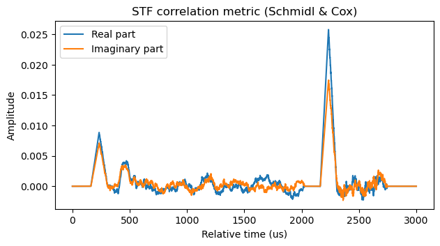
Due to this property, the STF correlates with the STF delayed by \(T_u/4\). Moreover, the overlap between the STF and the STF delayed by \(T_u/4\) is \(2T_s – T_u/4\), which is a relatively long interval. A variant of the Schmidl & Cox algorithm for the STF computes the metric\[C(t) = \int_t^{t+2T_s-T_u/4}x(s+T_u/4)\overline{x(s)}\, ds,\]where \(x(t)\) denotes the received signal. This metric presents a correlation peak when \(t\) coincides with the beginning of the STF.
As usual in the Schmidl & Cox algorithm, when \(t_0\) is near the beginning of the STF, the complex argument of \(C(t_0)\) measures the phase rotation of the signal in an interval of \(T_u/4\), so a carrier frequency offset estimate can be constructed as\[\widehat{\Delta f} = \frac{2\arg C(t_0)}{\pi T_u }.\]Here \(\widehat{\Delta f}\) has units of Hz. The range of this frequency estimator is limited by aliasing. The maximum carrier frequency offset that it can handle unambiguously is \(\pm 2/T_u\), which is \(\pm 62.5\, \mathrm{kHz}\).
One potential problem of frame detection using the STF is that the D-STF also causes a correlation peak in the metric \(C(t)\). Some form of filtering needs to be used to discard these peaks. For a conventional receiver, the extra peak is typically not a problem, because the receiver works with a state machine that indicates which part of the PPDU the receiver is processing. STF detection is only enabled when outside of a frame, and the D-STF is only seen while the receiver is processing a PPDU. For signal analysis, however, it can be more useful to come up with a stateless approach that first scans a recording for STF detections, and then it tries to decode the PPDU corresponding to each detection.
The following figure shows the correlation metric \(C(t)\) corresponding to the two frames in the Inspectrum waterfall above. We can see the triangular peak caused by the STF at the beginning of each frame. The D-STF in the first frame also causes a correlation bump. This bump isn’t triangular because the D-STF duration is only \(T_s\) and we are integrating for \(2T_s – T_u/4\), so the correlation is a trapezium plus interference from the adjacent symbols. We can also see that these frames have a significant carrier frequency offset, since the correlation peak is far from being real and positive.
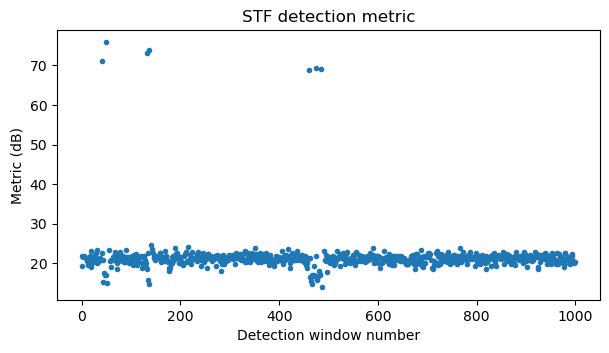
In the case of this recording, I have implemented a simplistic detection algorithm based on the metric \(C(t)\) that nevertheless works quite well and also filters out the peaks corresponding to the D-STF. The algorithm works as follows. First, the time axis is split into segments of length \(6 T_s\). In each segment, the time \(t_0\) where the maximum of \(|C(t)|\) is attained is found. Note that a PPDU always has at least 6 symbols, so by looking for the maximum in segments of length \(6 T_s\), we are guaranteed not to lose any PPDUs (unless there are colliding PPDUs).
The value of \(|C(t_0)|\) is now normalized by dividing by the average of the signal power \(|x(t)|^2\) in the time interval \([t_0 – T_s, t_0 – T_s/2]\). This has the advantage that if \(t_0\) is close to the start of the STF, then this interval will only contain noise from the inter-frame gap. On the contrary, if \(t_0\) corresponds to a local maximum inside a PPDU, then the interval will contain part of the PPDU, so the average power will be much higher and the resulting normalized metric will be much lower. This is how detections of local maxima inside a PPDU are filtered out.
Finally, there is an additional condition that \(|C(t_0)|\) must be greater or equal than \(|C(t)|\) for all \(t\) in the interval \([t_0 -2 T_s, t_0 + 2T_s]\). Otherwise, the detection candidate for this interval is discarded. The main reason to have this condition is that if the triangular correlation peak for the STF gets split between two of the segments of length \(6 T_s\), a detection candidate for this peak could be present in each of the segments, and one detection (the one in the segment that doesn’t contain the peak) would be wrong. This condition filters out the wrong detections caused by this situation.
The next plot shows the normalized detection metric in each window of length \(6 T_s\) for the beginning of the recording (detections in windows that are filtered out because of the last condition are not shown in the plot). Random noise gives a metric slightly above 20 dB. Correct detections of the STF of the 7 frames in this part of the recording have values around 70 dB. Some of the windows inside a frame have metrics lower than 20 dB, due to the normalization using the average power in a window preceding the detection candidate. With this plot it is clear that a detection threshold at 30 dB is a good choice.
Fine synchronization and channel estimation
The decoding of a PPDU begins with an estimate of the sample index in which the STF starts, obtained with the detection algorithm explained above. The first decoding step is to obtain an estimate for the carrier frequency offset (CFO). This is done in two steps. In the first step, \(\arg C(t_0)\) is used as explained above to obtain a coarse CFO. In the second step, the coarse CFO is removed, yielding a signal \(y(t)\), and a fine CFO is computed using the quantity\[C_2(t_0) = \int_{t_0}^{t_0 + T_s} y(s + T_s) \overline{y(s)}\, ds.\]This takes advantage of the fact that the two STF symbols are identical. It measures the phase rotation of the signal over a period of \(T_s\). Therefore, the fine CFO estimate is\[\widehat{\Delta f} = \frac{\arg C_2(t_0)}{2\pi T_s}.\]The fine estimate is a correction to the coarse estimate, so the two estimates are added to yield the total carrier frequency offset estimate.
The next step is to estimate the symbol time offset (STO). This is also done using the two STF symbols. The CFO estimate is used to remove the CFO from these symbols and then OFDM demodulation is performed by taking the FFT. In order to be tolerant to symbol timing errors, the FFT is done starting \(T_{cp}/2\) into the symbol. This is quite usual in OFDM demodulation. A correction in the form of a phase versus frequency slope needs to be applied to account for this time delay. However, the unusual aspect of the STF is that it doesn’t have a cyclic prefix (the useful symbol starts at the beginning of the symbol interval), so the correction needs to account for this.
As mentioned above, the STF only uses the subcarriers with indices divisible by 4, excluding the DC subcarrier. Pilot symbols as indicated by the formula below are modulated in these subcarriers. The definition of the STF dates back to the OFDM PHY introduced in 802.11a, and the same pilot sequence has been used in all the later PHYs.

After OFDM demodulation, the pilot sequence is wiped off, the two STF symbols are averaged together coherently, and only one out of every 4 subcarriers is taken. A zero is placed in the DC subcarrier position. This gives a sequence that has a phase versus frequency slope that corresponds to the STO. The STO is estimated in two steps. In the first step, an FFT of this sequence is computed and the bin in which the peak is located gives a coarse estimate of the slope. In the second step, this coarse slope is removed, the average phase is also removed, and a polynomial of degree 1 is fitted. The leading term of the polynomial is used as a fine estimate for the slope. The final estimate for the slope is computed as the sum of the coarse and fine estimates. The STO estimate is computed from this slope estimate.
Note that this algorithm can resolve the STO without aliasing problems as long as the slope is less than \(\pm 1/2\) cycles for each 4 subcarriers, which corresponds to a delay of \(\pm T_u/8\). The STF detection described above is quite likely to give an estimate for the STF location that is much more accurate than this.
Once the STO is determined by this procedure, the sample index in which the STF starts, which was determined by STF detection, is corrected with the STO rounded to an integer, and the remaining fractional part of the STO is remembered to be applied as a phase versus frequency slope correction after OFDM demodulation.
The next step is to use the LTF1 symbols to perform channel estimation. The LTF1 symbols are also somewhat special regarding the use of the cyclic prefix. Instead of each of the two symbols having its own cyclic prefix of duration \(T_{cp}\), a cyclic prefix of duration \(2 T_{cp}\) is included before the first useful symbol, and then the two identical useful symbols, each of duration \(T_u\) follow. This is a good idea, because since the two symbols are identical, the second symbol can use the end of the first symbol as its cyclic prefix. So effectively this doubles the cyclic prefix duration for free, obtaining more robustness to STO and multipath in the demodulation of the LTF1.
In hindsight, probably it would have been slightly better to use the LTF1 instead of the STF to estimate the STO. However, in this notebook I’m just trying to write a decoder that works well enough, rather than spending time to determine what is the best possible approach.
In the case when there are multiple space-time streams, the LTF symbols are multiplied by each of the columns of a matrix and transmitted simultaneously over all the space-time streams, allowing the receiver to jointly estimate all the channels. In the case of a single space-time stream, this boils down to the symbols transmitted directly over the single antenna.
The sequence of pilot symbols that is modulated in the 56 subcarriers occupied by the LTF is defined as in the VHT PHY introduced in 802.11ac (the S1G PHY takes many aspects from the VHT PHY). This matches the definition of the HT-LTF field defined in HT PHY in 802.11n, which is given here.

This sequence is an extension of a 52-subcarrier sequence that was originally defined in the OFDM PHY in 802.11a. The extension is done by prepending two 1’s and appending two -1’s.

As usual, I perform the FFT for OFDM demodulation \(T_{cp}/2\) before the start of the useful symbol. For the first LTF symbol, the double length cyclic prefix needs to be taken into account (the useful symbol begins \(T_{cp}\) later than usual). In hindsight I could have taken advantage of the double length cyclic prefix and started the demodulation \(T_{cp}\) before the start of the useful symbol, but in this recording the channel has very little delay spread, so this wouldn’t make any difference.
The demodulated LTF1 symbols are multiplied by the pilot symbol sequence to wipe the pilots off, the two symbols are averaged together coherently, and the result is taken as the channel estimate. The LTF1 symbols are equalized with this channel estimate in order to make a constellation plot.
For constellation plotting purposes only, the STF is demodulated again using the STO estimate obtained before, and equalized with the channel estimate. When this demodulation is done, it is necessary to take into account the amplitude scaling of the OFDM waveform. Since some OFDM symbols do not use the full set of 56 subcarriers, in order to normalize the power of all the OFDM symbols, their amplitude is divided by \(\sqrt{N^{\mathrm{Tone}}}\), where \(N^{\mathrm{Tone}}\) is the number of subcarriers occupied by this symbol. This normalization needs to be taken into account whenever \(N^{\mathrm{Tone}} \neq 56\) so as to perform the appropriate scaling in the receiver.
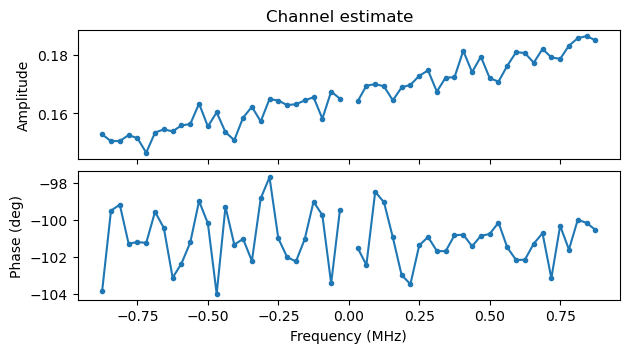
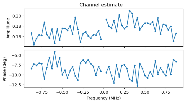
The following two plots show the channel estimates for the camera and the monitor screen respectively. These are taken from some of the first S1G_SHORT PPDUs in the recording. We can see that for some reason there is a noticeable slope in the amplitude of the camera signal, but otherwise the channel is well-behaved. There is no noticeable slope in the phase versus frequency, showing that the STO estimate is quite accurate.
SIG / SIG-A decoding
The next step is to decode the SIG or SIG-A field. This field occupies only 52 subcarriers. Four of these subcarriers are used as pilot tones. They are the ones in subcarriers \(\pm 7\) and \(\pm 21\), which are the subcarriers used for fixed pilots in 802.11 (these pilot subcarriers were initially defined in the OFDM PHY in 802.11a and used in all later PHYs).
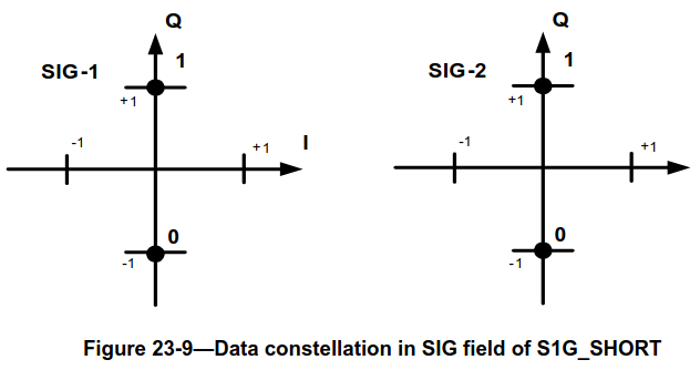
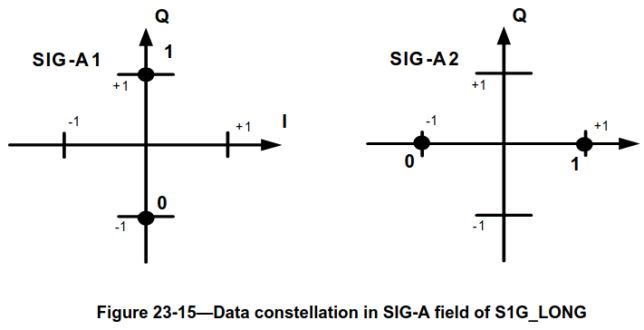
The data symbols in the SIG or SIG-A are BPSK modulated. A 90 degree rotation can be applied to some of these symbols. This rotation is what distinguishes SIG and SIG-A, and hence what can be used in the receiver to tell whether the PPDU is in S1G_SHORT or S1G_LONG format (since up to this point the two formats are identical).
The following two figures, taken from IEEE 802.11ah-2016, show the constellations of the two symbols of the SIG field of the S1G_SHORT PPDU and the two symbols of the SIG-A field of the S1G_LONG PPDU. The difference is that the SIG-A2 symbol does not use a rotated constellation.
In order to distinguish between SIG and SIG-A, after demodulation and equalization I compare the sum of the powers in the real and imaginary parts of the symbols in the second OFDM symbol. If the power in the real part is larger than in the imaginary part, the field is SIG-A.
To decode the SIG / SIG-A, we perform OFDM demodulation and equalization as indicated above. I do not look at the pilot symbols in the SIG / SIG-A, because the channel estimate from the LTF1 is recent enough and the CFO estimate is good enough that this channel estimate can be applied directly to the SIG / SIG-A (the sampling frequency offset does not accumulate a large enough STO to be noticeable either). Since only 52 subcarriers are used, the amplitude needs to be scaled by \(\sqrt{52/56}\).
The four pilot subcarriers in both OFDM symbols are modulated with the sequence \(\Psi = (1, 1, 1, -1)\). This sequence was originally defined in the OFDM PHY from 802.11a, and also used in the later PHYs. The data subcarriers in the two OFDM symbols constitute a total of 96 BPSK symbols that correspond to a 48-bit message encoded with an \(r = 1/2, k = 7\) convolutional encoder.
I will describe the encoding process of the SIG / SIG-A. The decoder reverses these steps. The process starts with a 48-bit message for the SIG or SIG-A. In the IEEE standard, the message is shown as two 24-bit messages, but it is probably better to think of it as the 48-bit concatenation. The last 6 bits of this message are zeros, used as tail to terminate the convolutional encoder. Before this tail, there is a CRC-4 that protects all the preceding fields. The following figure shows the structure of the SIG.
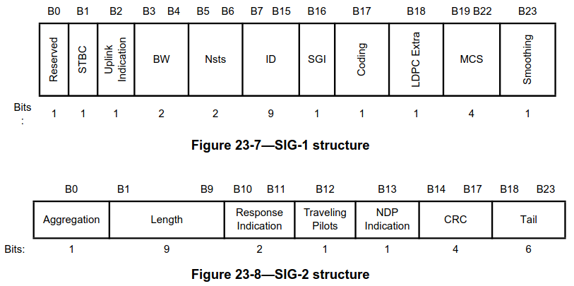
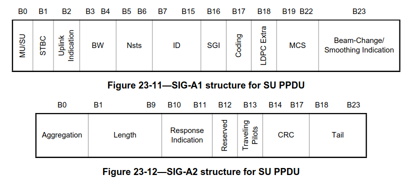
The structure of the SIG-A for SU PPDUs is shown here. There is also a different structure for MU PPDUs. They are distinguished by the first bit, which is a flag that indicates whether MU or SU is used. In this recording all the PPDUs are SU, so I will ignore MU. Note that the SIG and the SIG-A SU are quite similar, but not exactly the same. The MU/SU field is reserved in the SIG. The smoothing field from the SIG is repurposed as beam-change/smoothing in SIG-A. There is no NDP indication in SIG-A, since NDP means that the PPDU contains no data, so there is no reason to use S1G_LONG for an NDP PPDU. Finally, the position of the traveling pilots field is different.
The 48-bit message is convolutionally encoded. The encoder is shown in the following figure. It is the same encoder as used in CCSDS and many other applications.
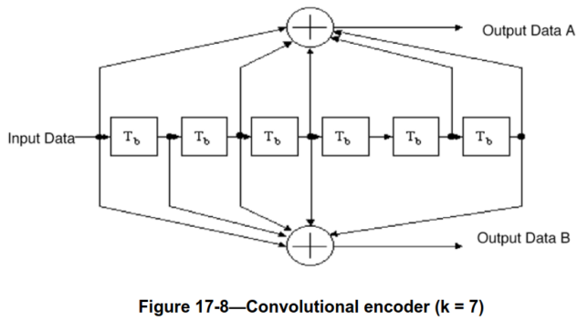
After encoding, the bits are interleaved. Interleaving is done independently by blocks of \(N_{CBPS}\) bits, where \(N_{CBPS}\) is the number of coded bits per OFDM symbol, which is 48 in this case. The goal of the interleaver is to put adjacently coded bits into non-adjacent subcarriers. The permutation is defined by the following formula, where \(k\) denotes the index of the bit before interleaving and \(i\) denotes the index of the bit after interleaving. Note that this is just a matrix interleaver where the data is written by rows into a matrix with 16 columns and then read by columns.

Finally, the interleaved bits are mapped to the OFDM data symbols, in lexicographic order of time and frequency.
To decode the SIG / SIG-A, soft symbols are extracted from demodulated OFDM data symbols, a deinterleaver is applied, and the Viterbi algorithm is used to decode the convolutional coding. The CRC-4 is checked and the frame is discarded (and a warning is printed) if the CRC is wrong.
The following shows the contents of the SIG-A for the first PPDU in the recording, which is an S1G_LONG PPDU.
MU/SU = 0
STBC = 0
uplink indication = 1
BW = 0
Nsts = 0
SIG ID = 0x121
short GI = 0
coding = BCC
LDPC extra = 1
MCS = 7 (64-QAM 5/6)
beam change / smoothing = 0
aggregation = 1
length = 36
response indication = 2
traveling pilots = 1
These are the contents of the SIG of the second PPDU in the recording, which is an S1G_SHORT PPDU.
STBC = 0
uplink indication = 0
BW = 0
Nsts = 0
SIG ID = 0x001
short GI = 0
coding = BCC
LDPC extra = 1
MCS = 1 (QPSK 1/2)
smoothing = 0
aggregation = 0
length = 40 (N_sym = 7)
response indication = 0
traveling pilots = 0
NDP indication = 0
With the knowledge of this values, we can save some work by only implementing the receiver features which are needed to decode these frames. STBC (space-time block coding) is never used. The Nsts field is always zero, which indicates only one space-time stream, so can ignore all the MIMO features. Coding is always BCC (binary convolutional coding), so we don’t need to implement LDPC, which is the other coding used by 802.11. Most frames use a long GI, but there are a few using short GI, so we need to implement both. The MCS varies a lot, so we need to implement all the constellations and coding rates, except for 256-QAM (MCS8), which is not used in this recording. Aggregation is used for longer PSDUs and not used for shorter PSDUs, so we need to implement both (according to the standard, aggregation must be always be used when the PSDU length is more than 511 bytes). Traveling pilots is used for longer PSDUs and not used for shorter PSDUs, so we need to implement both.
Beamchangeable portion channel estimation
In S1G_LONG PPDUs we need to process the D-STF and D-LTF fields. In this recording, it turns out that the beam change / smoothing indicator is set to zero in all the S1G_LONG PPDUs. For one space-time stream, the value of this field means that there is no change in the beamforming matrix \(Q\) between the omnidirectional and beamchangeable portions of the PPDU. We will see that the channel estimated with the D-LTF is essentially the same that was estimated with the LTF. Therfore, we could skip this channel estimation and ignore the D-STF and D-LTF fields. I don’t know why the stations are using S1G_LONG PPDUs in this recording, because it seems that S1G_LONG doesn’t provide any extra features over S1G_SHORT if beamforming isn’t used, while having three extra OFDM symbols of overhead. It turns out that in this recording all the data MAC frames use S1G_LONG, and all the other kinds of MAC frames use S1G_SHORT.
To perform channel estimation for the beamchangeable portion, first the three header symbols (D-STF, D-LTF1 and SIG-B, which is a repetition of D-LTF1 in these SU PPDUs) are OFDM demodulated. The STO and CFO that have been previously determined with the omnidirectional portion are applied in this demodulation, and as usual, the beginning of the FFT is taken to be \(T_{cp}/2\) after the start of the symbol.
The pilot sequence used in the D-LTF1 and SIG-B is the same as the sequence used in the LTF1. The sequence is wiped off, the D-LTF1 and SIG-B are averaged coherently, and the result is taken as the channel estimate.
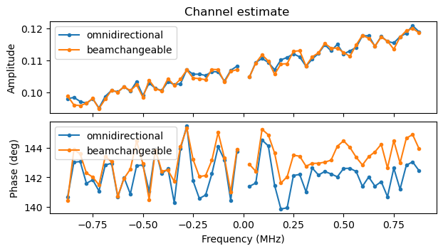
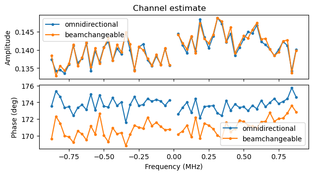
The following two plots compare the channel estimates for the omnidirectional and beamchangeable parts of the first S1G_LONG PPDUs of the camera and monitor screen (respectively) in the recording. We see that the omnidirectional and beamchangeable channels are nearly the same, which means that beamforming is not used in the beamchangeable portion. The small difference in phase in the channel estimates of the monitor screen PPDU is likely due to a small residual CFO.
Additionally, in this step the D-STF pilot sequence (which is the same as the one used in the STF) is wiped off. The D-STF, D-LTF1 and SIG-B symbols are equalized with the beamchangeable portion channel for constellation plotting purposes.
Data demodulation
The final part of the PPDU contains the data symbols. The occupy the full set of 56 subcarriers, with 4 subcarriers reserved for pilots. The first step to demodulate the data is to find how many OFDM symbols are used by the data field of the PPDU. How this is done depends on the value of the aggregation field in the SIG/SIG-A. If aggregation = 1, then the length field in the SIG/SIG-A directly contains this number of OFDM symbols.
If aggregation = 0, then the length field contains the PSDU length in bytes instead. From this value, we need to calculate the number of OFDM symbols that are required to transmit this PSDU. The calculation is done as follows. To the PSDU length in bits we need to add the length of the SERVICE field, which is 8 bits, and the length of the convolutional encoder tail, which is 6 bits. Then we need to know the number of data bits carried in each OFDM symbol, \(N_{\mathrm{dbps}}\). This is computed from the MCS index, which is also contained in the SIG/SIG-A. A table indicates the corresponding constellation and coding rate. Here the table for 2 MHz bandwidth and one spatial stream (which is what is used in the recording) is shown. The constellation and coding rate do not depend on the bandwidth and number of spatial streams, but other values in the table such as the number of OFDM subcarriers and the data rate do.
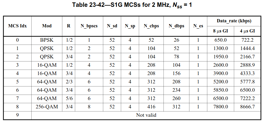
From the constellation and coding rate we calculate how many data bits are carried in a single subcarrier (this might be a fractional number) and then multiply that value by 52 data subcarriers to obtain \(N_{\mathrm{dbps}}\) (which is also listed in the table). Finally, we divide the total length of the data in bits (including the SERVICE field and tail) by \(N_{\mathrm{dbps}}\) and take the ceiling to obtain the required number of OFDM symbols.
Once the number of OFDM symbols is known, we perform OFDM demodulation of these symbols in the usual way. Here something else we need to take into account is whether short GI is used. The short GI is half of the normal GI (so it has duration \(T_u/8\) instead of \(T_u/4\)). In PPDUs using short GI, all the data symbols except the first one use the short GI. The first data symbol, as well as all the other previous symbols always use the normal GI. Whether short GI is enabled in a PPDU is indicated in its SIG/SIG-B. For short GI PPDUs we still demodulate each OFDM symbol starting halfway into the cyclic prefix, but we need to take into account the different cyclic prefix length to compute the appropriate sample indices.
After OFDM demodulation is done, the symbols are equalized either with the channel estimate in S1G_SHORT PPDUs or the beamchangeable portion channel estimate in S1G_LONG PPDUs. The next step is to perform a second equalization by using the pilot symbols of the data field. This is necessary because when using aggregation there are some PPDUs that carry multiple IP packets and so they can be quite long, as illustrated by this part of the recording which has some PPDUs that are approximately 20 ms long. The channel estimate done with the LTF1 or D-LTF1 does not stay good for the whole duration of the PPDU, mostly due to residual CFO and sampling frequency offset (SFO). (Note that we haven’t estimated and corrected the SFO).

To equalize using the pilots, first we need to locate the 4 pilot subcarriers and wipe off their modulation. The pilot subcarriers that are used depend on the value of the traveling pilots field in the SIG/SIG-A. If traveling pilots = 0, then the fixed pilot subcarriers \(\pm 21\) and \(\pm 7\) are used in all the OFDM symbols of the data field.
If traveling pilots = 1, each OFDM symbol of the data field uses different subcarriers for the 4 pilots. A table defines the subcarrier indices of the 4 pilots based on a pattern index \(m\). The table corresponding to the configuration in this recording is shown below. It has 14 pattern index entries. The first data symbol uses pattern index \(m = 0\), the next uses \(m = 1\), and so on, repeating the pattern every 14 data symbols.
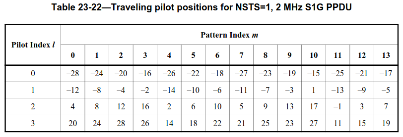
Additionally, traveling pilots use amplitude 1.5, instead of 1.0 as the fixed pilots do. This would need to be taken into account if the pilot amplitude was used for equalization. Here we only take it into account when plotting the constellation.
The BPSK symbols that are modulated on the pilots are computed in the same way for traveling pilots and fixed pilots. These symbols are formed by the multiplication of two sequences. The first sequence, \(P_n\), is constructed by a circular shift of the base sequence \(\Psi = (1, 1, 1, -1)\) that we have already used with the SIG/SIG-A pilots. The sequence \(P_n\) is defined as\[P_n = (\Psi_{n \mod 4}, \Psi_{(n+1) \mod 4}, \Psi_{(n+2) \mod 4}, \Psi_{(n+3) \mod 4}),\]where \(\Psi_0\) denotes the first component of the vector \(\Psi\) and so on. The first data symbol uses \(P_0\), the second uses \(P_1\), etc. This sequence makes one of the pilot subcarriers have the opposite sign as the others. The subcarrier with this property rotates in each symbol.
The second sequence is denoted as \(p_m\). This is a pseudorandom sequence of 127 elements which are \(\pm 1\). For some reason, the first data symbol uses \(p_2\), the second uses \(p_3\), and so on, repeating the sequence cyclically every 127 data symbols. (Here I’m simplifying the exposition. In MU PPDUs, the first data symbol actually uses \(p_3\) and \(P_1\)). So data symbol \(n\) uses \(p_{(n+2) \mod 127}\). The values of the 4 pilot subcarriers in data symbol \(n\) are computed as the product \(P_n p_{n+2}\).
The pseudorandom sequence \(p_n\) was first defined in the OFDM PHY in 802.11a. In that PHY it was essential to avoid producing CW tones in the pilot subcarriers, because the pilot subcarrier indices were always fixed and the rotation \(P_n\) was not used (all the symbols used the vector \(\Psi\)).

The rotation \(P_n\) was introduced in the HT PHY in 802.11n, and the traveling pilots feature is new in 802.11ah. Even the VHT PHY from 802.11ac has fixed pilot locations. Probably traveling pilots are intended to give robustness against narrowband interference, which can be have devastating effects if the interference happens to coincide with the frequency of some of the fixed pilots.
The equalization using the pilots is done for the phase only, since the amplitude of the signal doesn’t vary significantly over the frame duration (at least in the kind of channel present in this recording). The main goal of this equalization is to correct residual CFO and all the SFO, which affect the phase of the channel only. The equalization is done by fitting a degree one polynomial to the phases of the 4 pilot symbols. This polynomial represents a linear (actually affine) phase versus frequency. Its coefficients correspond to a phase versus frequency slope, which corresponds to a time delay and is caused by SFO, and to a phase offset, which is caused by residual CFO.
Since phase wraps modulo \(2\pi\), this linear fit is potentially problematic. For instance, if the phase versus frequency slope is large, the phase could wrap throughout the signal bandwidth. In the STO estimation done with the STF, I used an FFT to handle this. In this case, the strategy is to perform the equalization in an incremental manner. Recall that all the OFDM symbols in the data field have already been equalized with the channel derived from the LTF1 or D-LTF1. First, a degree one polynomial is fitted to the phase of the pilots of the first data symbol. The phase of the pilots for the second data symbol is equalized with this degree one polynomial, and another degree one polynomial is fitted to the resulting phase. This polynomial represents the difference in the channel phase between the first and second data symbols, so it is added to the polynomial obtained with the pilots of the first data symbol to obtain a polynomial that represents the channel for the pilots of the second symbol. In general, the \(n+1\)-th symbol’s pilot phases are equalized the polynomial \(q_n\) obtained with the \(n\)-th symbol’s pilots, and a polynomial \(r_{n+1}\) is fitted to the resulting phase. The polynomial \(q_{n+1}\) is computed as \(q_{n+1} = q_n + r_{n+1}\). This approach has the advantage that the fit is only done to the phase difference between one symbol and the next, which is always small and doesn’t have wraps, while the coefficients of the polynomials \(q_n\) can grow as needed, and account for any phase wraps that might happen.
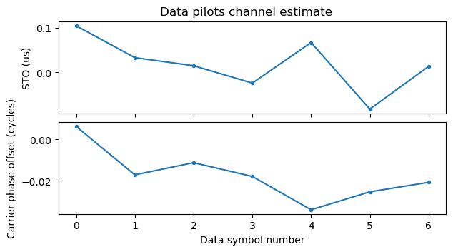
Here is an example of the channel estimate using the pilots in the data field for an S1G_LONG PPDU that is particularly large (386 data symbols, which is 15.44 ms). We can see that the STO increases by approximately 0.25 usec over the duration of the data field. This corresponds to an SFO of approximately 16 ppm. The accumulated STO is much smaller than the cyclic prefix duration, so there is no reason to change the starting point of the FFT used for OFDM demodulation to account for this STO. The CFO increases by approximately -0.12 cycles over the data field duration. This corresponds to a residual CFO of approximately -7.8 Hz.
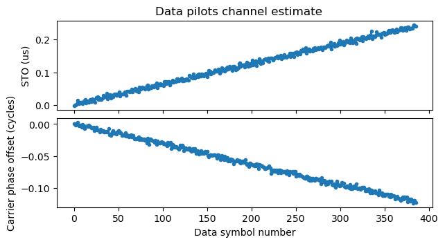
After the polynomials corresponding to the pilots of each of the data symbols have been computed, the phase of the data symbols is equalized using these polynomials (each polynomial is used to equalize the corresponding OFDM symbol).
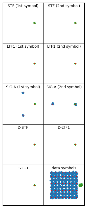
The figure below shows the equalized symbols for all the fields of this large S1G_LONG PPDU. Pilot sequences have always been wiped off, and the pilot symbols are shown in green, while data symbols are shown in blue. The reference locations for the symbols are indicated with a small red dot. This PPDU uses MCS 7, which is 64-QAM 5/6. Looking at the resulting 64-QAM constellation, we can see that the equalization is working well.
The last step in demodulating the data symbols is to obtain the coded bit LLRs. To compute them, I’m using the same approach as in my posts about LTE. This is to use the formula\[L_k = \max^*_{b_k(z) = 0,\, z \in C}\left(-\frac{|y-z|^2}{2 \sigma^2}\right) – \max^*_{b_k(z) = 1,\, z \in C}\left(-\frac{|y-z|^2}{2 \sigma^2}\right).\]Here \(y \in \mathbb{C}\) denotes the received symbol, \(C\) denotes the constellation set, \(b_k(z)\) denotes the hard \(k\)-th bit corresponding to the constellation symbol \(z\), the number \(L_k\) is the LLR corresponding to the \(k\)-th bit, \(\sigma\) is the standard deviation of the real (or imaginary part) of the AWGN in \(y\), and the reduction function \(\max^*\) is defined as\[\max^*(x_1, \ldots, x_n) = \max^*(x_1, \max^*(x_2, \ldots, x_n)),\]with the \(\max^*(x_1, x_2)\) function of two arguments given by the max*-safe function that is defined for instance by AFF3CT.
When reviewing this I’ve noticed that I had made a mistake in the formula in my LTE notebooks. I was missing the square in the \(|y-z|^2\) terms. This distorts the LLRs, so I will need to fix that.
The LLR formula requires an estimate of the noise standard deviation \(\sigma\). In this demodulator I’m obtaining an estimate by computing the RMS noise of the pilot symbols of the data field (a single value of \(\sigma\) is estimated for the whole PPDU).
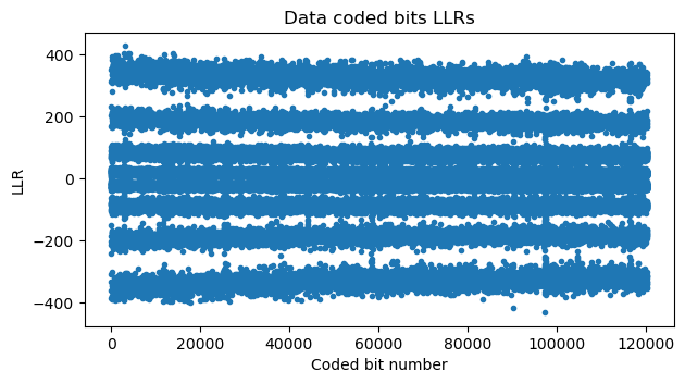
Here is a plot of the LLRs corresponding to this large S1G_LONG PPDU. This shows the 4 characteristic “amplitude” levels of 64-QAM. Due to the gray-coded constellation, the 2 LSBs are less robust, since they change in neighbouring symbols (either in the vertical or horizontal direction), while bits closer to the MSB are more robust.
Data decoding
The encoding of the data is similar to the encoding of the SIG/SIG-A. There is a previous step that is not present in the SIG/SIG-A, which is to scramble the data with the output of an LFSR. Then the data is convolutionally encoded, and the coded bits are interleaved. There are some additional complications in these steps compared to the SIG/SIG-A because the coding rate can be different from 1/2, so there is a puncturer after the basic r = 1/2, k = 7 convolutional encoder, and because the interleaver depends on the number of bits per symbol in the constellation.
The first step in the decoding process is to deinterleave the LLRs. The following quantities are important in the definition of the interleaver: First, \(N_{\mathrm{BPSCS}}\) is the number of bits in a constellation symbol (number of bits per subcarrier and symbol). For instance, for 64-QAM, \(N_{\mathrm{BPSCS}} = 6\). Second, \(N_{\mathrm{CBPSSI}} = 52 N_{\mathrm{BPSCS}}\) is the number of coded bits per OFDM symbol. The interleaver always works in blocks of \(N_{\mathrm{CBPSSI}}\) bits, thus affecting each OFDM symbol separately. Finally, the parameters \(N_{\mathrm{COL}} = 13\) and \(N_{\mathrm{ROW}} = 4 N_{\mathrm{BPSCS}}\) are used to define the matrix interleaver.
The interleaver is defined by two permuations, which are applied consecutively to each block of \(N_{\mathrm{CBPSSI}}\) bits. The first permutation is defined by the following formula, where \(i\) is the index after the applying the permutation and \(k\) is the index before applying the permutation. As for the SIG/SIG-B, this is a matrix interleaver where the data is written by rows into a matrix and read by columns.

The second permutation is defined by the following formula, where \(j\) is the index after applying the permutation and \(i\) is the index before applying the permutation. The value \(s\) is defined as \(s = \max(1, N_{\mathrm{BPSCS}}/2)\).

There is a third interleaver permutation, but is only used when there are multiple spatial streams, so I will ignore it here.
The inverses of these two permutations are applied in reverse to deinterleave the LLRs. After this, the puncturing needs to be undone by inserting bits with an LLR of zero in all the bit positions that were punctured. Denoting by \(A_n\), \(B_n\) the bits produced by each of the two output branches of the convolutional encoder, the following coding rates and puncturers are defined:
- Rate 1/2. No puncturer is used.
- Rate 2/3. The code is punctured to obtain \(A_0, B_0, A_1\), etc. (odd \(B\) outputs are punctured).
- Rate 3/4. The code is punctured to obtain \(A_0, B_0, A_1, B_2\), etc. (\(A\) outputs which are congruent with 2 modulo 3 and \(B\) outputs which are congruent with 1 modulo 3 are punctured).
- Rate 5/6. The code is punctured to obtain \(A_0, B_0, A_1, B_2, A_3, B_4\), etc.
After depuncturing, the Viterbi decoder is run to decode the message. This Viterbi decoder is the same that was used to decode the SIG/SIG-A. Once the Viterbi decoder finishes, I re-encode the message and estimate BER by counting bit errors in the bits that were not punctured. This is used mainly as a check that the decoder implementation is working correctly.
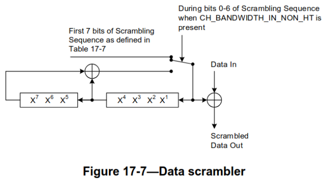
The final step in decoding the data is descrambling. The scrambler is the same that was originally defined by the OFDM PHY in 802.11a. In 802.11ah, the scrambler works as follows. The beginning of the data is an 8-bit SERVICE field. The first 7 bits of the SERVICE field are zeros and are used to contain the scrambler initialization in the scrambled message. The remaining bit is reserved, and it is also supposed to be zero.
The transmitter chooses a 7-bit initialization value for the scrambler before scrambling the message. It then scrambles the message according to the circuit below. During the first 7 bits, the initialization sequence is loaded into the LFSR at the same time that is used to scramble the first 7 bits of the SERVICE field. Since these bits are zero, the scrambled SERVICE field contains the 7-bit initialization value, and the receiver can use it to initialize the descrambler correctly. After these initial 7 bits, scrambling continues normally by using the LFSR output. The 6 tail bits for the convolutional encoder are not scrambled, since they must be zeros.
After descrambling, we can remove the SERVICE field, the 6 tail bits, and any padding that was added when aggregation = 0 in order to obtain an integer number of OFDM symbols. In this way, we obtain the PSDU (when aggregation = 1, the MAC layer already supplies a PSDU that is padded to an integer number of OFDM symbols). Something to keep in mind is that IEEE 802.11 transmits bytes in a least-significant-bit-first order (for instance, for each byte, its LSB is the bit that is sent first into the scrambler). So typically the bits in each byte need to be reversed at some point to undo this effect. However, some of the fields contained in the PSDU are intended to be interpreted in this LSB-first order, so it can be advantageous to switch to MSB-first at the last possible moment.
Now the processing is different depending on whether aggregation is used. The case aggregation = 1 will be discussed in the next section. When aggregation = 0, the PSDU is a single MAC PDU, which contains a FCS (CRC-32) at the end. At this point we have a sequence of bytes whose length is given by the length field in the SIG/SIG-A (which has the meaning of PSDU length when aggregation = 0). We can switch the bytes to MSB-first and then check the CRC-32.
However, in the frames in this recording I have found what looks like a bug in the implementation of these radios. It seems that the PSDU length transmitted in the SIG/SIG-B is the smallest multiple of 4 larger of equal than the true PSDU length. Therefore, for PSDUs whose true length is not a multiple of 4, some guesswork is required by removing 1, 2, and 3 bytes at the end of the PSDU and running the FCS check for each of these options to find which is the correct one. I’m almost sure this is a bug, because I haven’t seen anything in the IEEE standards that says that the PSDU length must be a multiple of 4. I wonder how the receivers in these radios are implemented, since I don’t see a way to obtain a good FCS check other than determining the correct PSDU length by trying the 4 different options.
MPDU aggregation
MPDU aggregation is a feature introduced by 802.11n that allows sending multiple MPDUs (MAC PDUs) in a single PPDU (radio frame). It is enabled by setting the aggregation bit to 1 in the SIG/SIG-A. In 802.11ah, it is mandatory to use aggregation for PDSU lengths above 511 bytes, since the length field in the SIG/SIG-A (which means PSDU length when aggregation = 0) has only 9 bits.
When aggregation is used, the PSDU is an A-MPDU. This A-MPDU is structured as shown in these diagrams. The A-MPDU is divided into subframes. Each of them carries a MAC PDU. The subframes always have a length that is a multiple of 4 bytes, and padding is used if needed. The A-MPDU is padded to the length required by the physical layer (this padding was introduced by the VHT PHY in 802.11ac). The padding is done first by adding padding subframes, each of which has 4 bytes, and then by adding 1, 2 or 3 extra padding bytes if needed.


An A-MPDU subframe is formed by a 4-byte MPDU delimiter, which plays the role of a header, an MPDU (unless the subframe is an EOF padding subframe), and padding as needed to pad to a length multiple of 4 bytes.


The MPDU delimiter has the following fields:
- An EOF flag, which is only set to 1 in the EOF padding subframes and also in the first A-MPDU subframe if the A-MPDU carries a single non-padding subframe.
- An MPDU length field, which indicates the length of the MPDU in bytes.
- A CRC-8 which protects the previous fields.
- A delimiter signature which contains the ASCII character
N(in LSB-first order)
Since the A-MPDU might contain bit errors from decoding, the CRC can be used to check if the MPDU length is correct. If this is the case, the receiver can know where the next subframe starts simply by counting bytes. If this MPDU length is wrong, the receiver cannot do this. In my Jupyter notebook I’m simply stopping the parsing of this A-MPDU when this happens. However, the delimiter signature field provides a way for the receiver to recover. It can scan in 4 byte steps (since the subframe size is guaranteed to be a multiple of 4 bytes) until it finds a delimiter signature with the correct value, and then it can check the CRC-8. If the check is successful, the receiver has found the beginning of another subframe in the A-MPDU.
Note that the fields in the MPDU delimiter are parsed in LSB-first order more easily, so I’m switching the order to MSB-first only after extracting each MPDU.
PCAP output
As in my LTE notebooks, I’m writing the decoded frames to a PCAP file for later analysis with Wireshark. This is done using scapy. The frames that I write to the PCAP file are MAC PDUs with a Radiotap header, which contains “metadata” about the frame. This means that PPDUs using aggregation end up as multiple frames in the PCAP. It is possible to store A-MPDUs in a PCAP file and parse them in Wireshark by using a PPI header, as shown by this example. However, for simplicity, and because scapy doesn’t have good support for PPI, I decided to store the MAC PDUs in an A-MPDU as different frames in the PCAP.
I’m making as much use as I can of the Radiotap header. I’m using the flags field to store whether the FCS is correct (I’m writing all the MPDUs regardless of their FCS check status) and whether short GI is used. I’m using the A-MPDU field to track the properties about MPDUs obtained from A-MPDUs. Finally, I’m using the S1G header to store all the information supported by it (except the RSSI, which I’m not estimating).
When using Wireshark to look at this PCAP, I noticed that the parsing of the MAC header of S1G control frames (which are slightly different from non-S1G control frames, as indicated in Section 9 of IEEE 802.11ah), wasn’t implemented. I sent a PR that implements this, but this isn’t in a stable release yet, so it’s necessary to build Wireshark from source to see the correct parsing for these frames.
Nevertheless, there are many frames for which Wireshark complains that they are malformed, or shows wrong information. I have looked at these frames carefully, and I think that this is caused by more bugs in these radios. The FCS for these frames is correct, so I think that rules out any possible mistakes on my side.
As an example, Wireshark complains that this BlockAck frame is malformed. The problem is that the fragment is not 0, as it should. The transmitter is ignoring the fact that the SSC field is split into a sequence number subfield and a fragment subfield. This is a BlockAck for the frame with sequence number 1322 (0x52a in hex), but this value has been written over the whole SSC field instead of only the starting sequence number subfield. Wireshark then interprets this frame as using a feature of 802.11ax that uses non-zero bits in the fragment number to indicate a longer BlockAck bitmask, and then it fails dissection because the frame is not long enough.
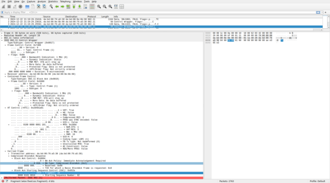
Other frames such as the S1G Beacon also show as malformed, and there many other minor problems (for instance, in the frame above, the bandwidth indication in the flags and +HTC should be 2 MHz instead of 1 MHz, and the coding type in the +HTC shouldn’t be LDPC).
Recording analysis results
Here I show some of the results obtained when using this Jupyter notebook to analyze my recording.
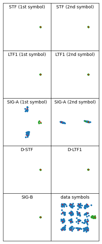
Something that I’ve observed is that PPDUs transmitted by the monitor screen have some kind of distortion or noise in the symbols in which variable data is transmitted. This effect is mostly curious, and I can’t think of any shortcomings in my receiver implementation that could explain it. The constellation below shows an example of a PPDU with this problem. The LTF1 constellation is very tight, since that is the symbol used for channel estimation. The STF constellation is also quite tight. However, the SIG and data symbols have much more noise.
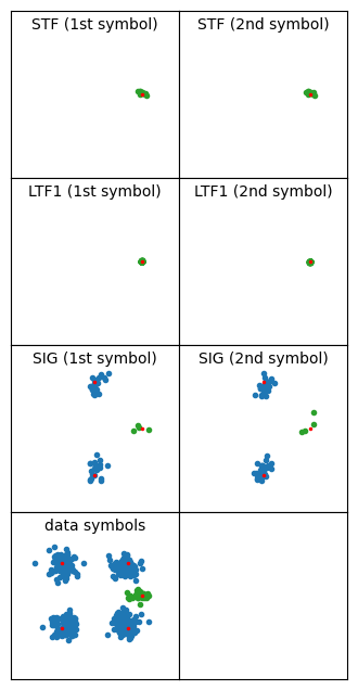
This is a rather short PPDU (only 7 OFDM data symbols), so the channel estimation using the data pilots isn’t doing much (the channel estimate is shown below). Disabling equalization with the data pilots yields basically the same kind of constellation, so it isn’t a problem caused by the data pilots equalization.
I don’t know what is the reason for this problem. It doesn’t happen with the frames transmitted by the monitor screen (or it happens in a much weaker way). I think that it is related to the spectral leakage that I showed in some of the Inspectrum waterfalls. Perhaps the transmitter tends to clip with data sequences, but not with STF and LTF sequences, which I guess are designed to have low peak amplitude.
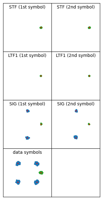
Here is an example of an S1G_LONG PPDU transmitted by the monitor screen. The additional noise in the symbols carrying data is not as high as in the previous example, but the difference between the STF, LTF1, D-STF, D-LTF1, and SIG-B fields, which all have a very tight constellation, and the SIG-A and data fields is remarkable.
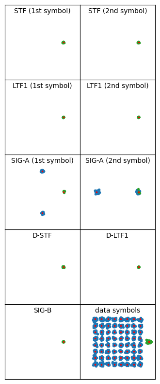
The camera radio perhaps has the same problem, but the effect is not as strong as in the monitor screen. The following two plots show the constellation for an S1G_SHORT PPDU and an S1G_LONG PPDU transmitted by the camera. The noise in the SIG/SIG-A and data symbols is visibly higher than in the other symbols, but the data constellation is still reasonably tight, so even 64-QAM has few bit errors.
Another modulation problem that I have found relates to the use of short GI. This option is enabled only a few times by the monitor screen. I’ve found that often my decoder produces an FCS error with short GI frames. The problem is that the data constellation is not good enough. For example, the following PPDU uses short GI and MCS 7 (64-QAM 5/6), and it is clear that the constellation is too noisy for a good decode.
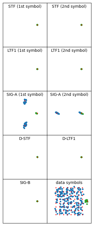
Perhaps this problem is just another manifestation of the increased noise in data symbols that I’ve described above. Maybe it is more prominent in short GI frames because of the increased tendency of using a high MCS together with short GI.
The following screenshot shows all the short GI frames in Wireshark. The frames with an FCS error are marked in black and red. All of them use MCS 6 or 7. Other short GI frames with lower MCS are decoded successfully. More importantly, it seems that the decoding problem is not only with my IQ recording and decoder implementation. All the frames for which my decoder has an FCS error are then retransmitted with a lower MCS (look at the repeated SNs). This means that the camera wasn’t able to decode these frames either, and so the monitor screen had to do a retransmission.

The following plot is the constellation of the second frame in this list, which is a retransmission in MCS 3. The constellation is still rather noisy, but since it is 16-QAM instead of 64-QAM, it can be decoded successfully.

In fact, looking at the list of frames transmitted by the monitor screen that use an MCS of 6 or more, we see that most of them have a wrong FCS, regardless of whether they use short GI. On the other hand, all the frames with MCS lower than 6 are successfully decoded except for one.

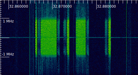
An interesting part of the recording is around the 32.87 seconds mark. The following figure shows the corresponding Inspectrum plot. We can see that the power of the monitor screen signal has decreased greatly, and there is frequency-selective fading.
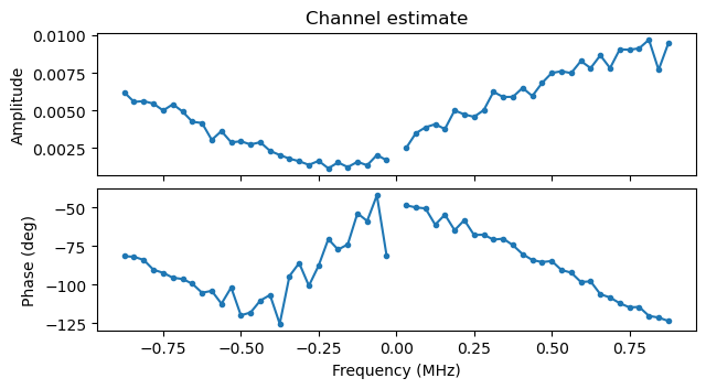
The following plots show the channel estimate and the constellation plot for one of these packets with fading (the one at 38.878 s). The packet can still be decoded correctly despite the fading.
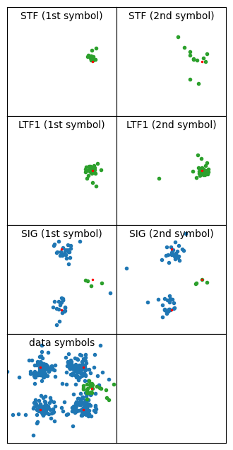
I don’t know why this fading happened. The camera and the monitor screen were located in two different rooms in the house, and the Pluto doing the IQ recording was approximately midway between them. Maybe someone walked near the monitor screen or even picked it up, but what I find interesting is that the duration of this fading is quite brief. It only starts to be noticeably around 32.63 seconds, and stops around 33.06 seconds, so the event that produced the fading only lasted half a second.
When I started analyzing this recording, I intended to learn the details about how 802.11ah works. I didn’t expect to be finding problems about the way that it is implemented in this product, in the same way that I haven’t found any implementation problems in my posts about LTE and 5G NR. However, I’ve already pointed out several problems that seem to be caused by the implementation in this product. These range from badly formatted MAC layer frames to modulation quality issues. There are many issues, to the point where I could probably write a follow up post explaining all of these in detail.
One problem that is immediately obvious is the address headers in the frames transmitted by the monitor screen. The camera and monitor screen use the MAC addresses da:bd:00:76:a5:30 and da:bd:00:9e:6b:90 respectively (these are locally administered addresses, which is somewhat unusual for a consumer product). The monitor screen is the AP.
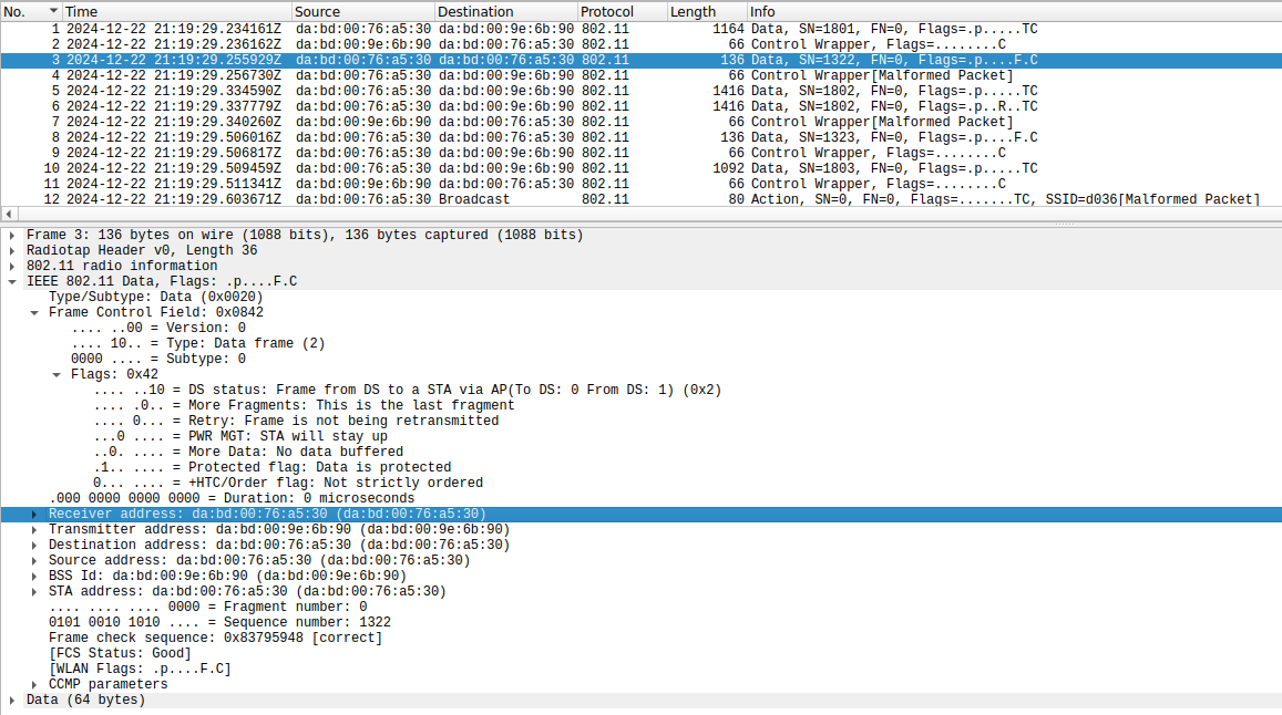
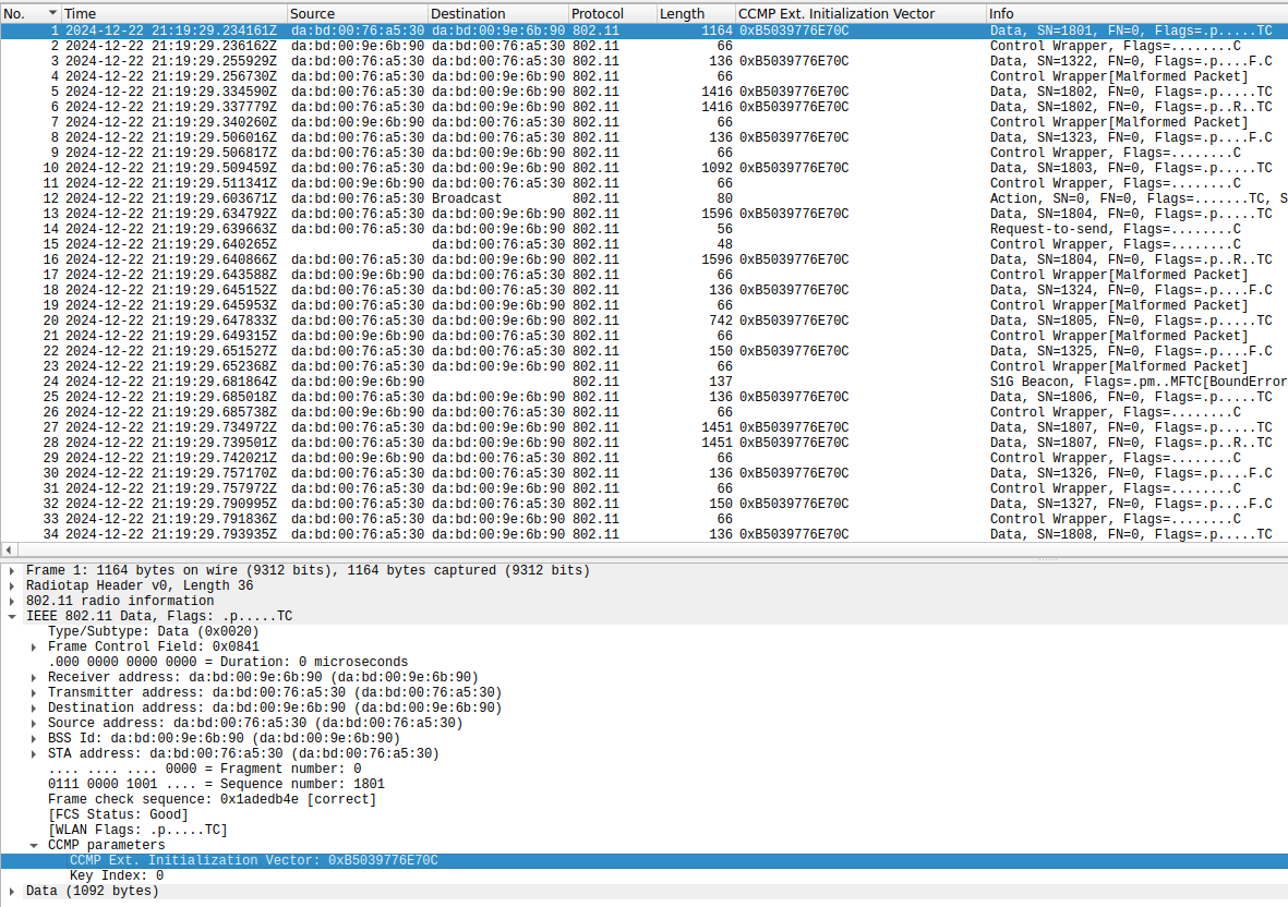
As shown in the Wireshark screenshot above, data frames transmitted by the monitor screen use:
- Address 1 (receiver address)
da:bd:00:76:a5:30(which is correct) - Address 2 (transmitter address)
da:bd:00:9e:6b:90(which is also correct) - Address 3 (source address)
da:bd:00:76:a5:30(which is not correct; it should beda:bd:00:9e:6b:90).
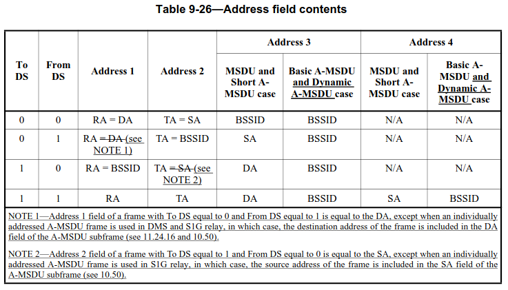
More in detail, these frames have To DS = 0, From DS = 1, so according to the table below address 3 indeed should contain the source address.
The most striking problem that I’ve found regards encryption. All the data frames use CCMP (WPA2), which is good. However, the CCMP initialization vector is always the same. More strikingly, the camera and monitor screen use the same initialization vector, which indicates that it is perhaps hardcoded in the firmware rather than generated randomly at some point. Correct usage of CCMP requires using a different initialization vector for each frame encrypted with the same key, because CCMP is based on a stream cipher, and it is only safe to apply the same stream to one plaintext. Typically, the initialization vector is a counter to avoid reusing it.
Here we can see the same CCMP IV being used in all the data frames.
To show that this is indeed a security problem, compare the encrypted data of the two following small data frames, which are sent by the monitor screen as response to large data frames sent by the camera. Possibly they are TCP ACKs. The encrypted data of these two frames begins in exactly the same way. This is not surprising, because they probably have many fields with the same values in the IP and TCP headers, and they are encrypted by XORing with the same stream due to the IV reuse. This should never happen in a properly designed system.


Code and data
The IQ recording used in this post can be downloaded here. The remaining files are in this Github repository. This contains the Jupyter notebook used for analysis, the GNU Radio flowgraph used for resampling from 3.84 Msps to 4 Msps, and the output PCAP file.
Simply incredible. Thank you for writing this.