During the last few months, I have been working on gr4-packet-modem. This is a packet-based QPSK modem that I’m writing from scratch using the GNU Radio 4.0 runtime. The gr4-packet-modem project is funded by GNU Radio with an ARDC grant, and its goal is to produce a complete digital communications application in GNU Radio 4.0 that can serve to test how well the new runtime works in this context and also as a set of examples for people getting into GNU Radio 4.0 development. I have presented gr4-packet-modem in the EU GNU Radio days (see the recording in YouTube).
In July, Frank Zeppenfeldt, who works in the satellite communications group in ESA, got in touch with me regarding an opportunity to test gr4-packet-modem on a C-band transponder on Intelsat 37e. His group is running a project with industry about a test campaign of IoT communications over GEO satellites, and they have rented a 1 MHz C-band transponder on Intelsat 37e for some time. The uplink is somewhere around 5.9 GHz, and the downlink somewhere around 3.7 GHz. As part of the project, they have setup a PC and a USRP B200mini in a teleport in Germany that has a large antenna to receive the downlink. There is remote access to this PC, so all the downlink part of the experiments is taken care of: IQ recordings can be made and receiver software can be run in this PC. Therefore, if I could set up an uplink station at home in Madrid (which is actually slightly outside the edge of the Europe C-band beam, as it can be seen in this document), then I would be able to run some tests of gr4-packet-modem by running the transmitter in my laptop and the receiver in the remote PC at the teleport.
As I mentioned to Frank when he proposed this experiment, I haven’t implemented an FEC for the payload of the packets in gr4-packet-modem, because I wanted to have full freedom in setting the size of each packet (to test latency with different packet sizes), and a good FEC scheme usually constraints the possible packet sizes (see gr-packet-modem waveform design for more details). Testing a modem that uses uncoded QPSK over a GEO channel is somewhat pointless, but Frank and I agreed that this would be a fun experiment, even if not too interesting from the technical point of view. In the rest of the post I explain the test set up and results.
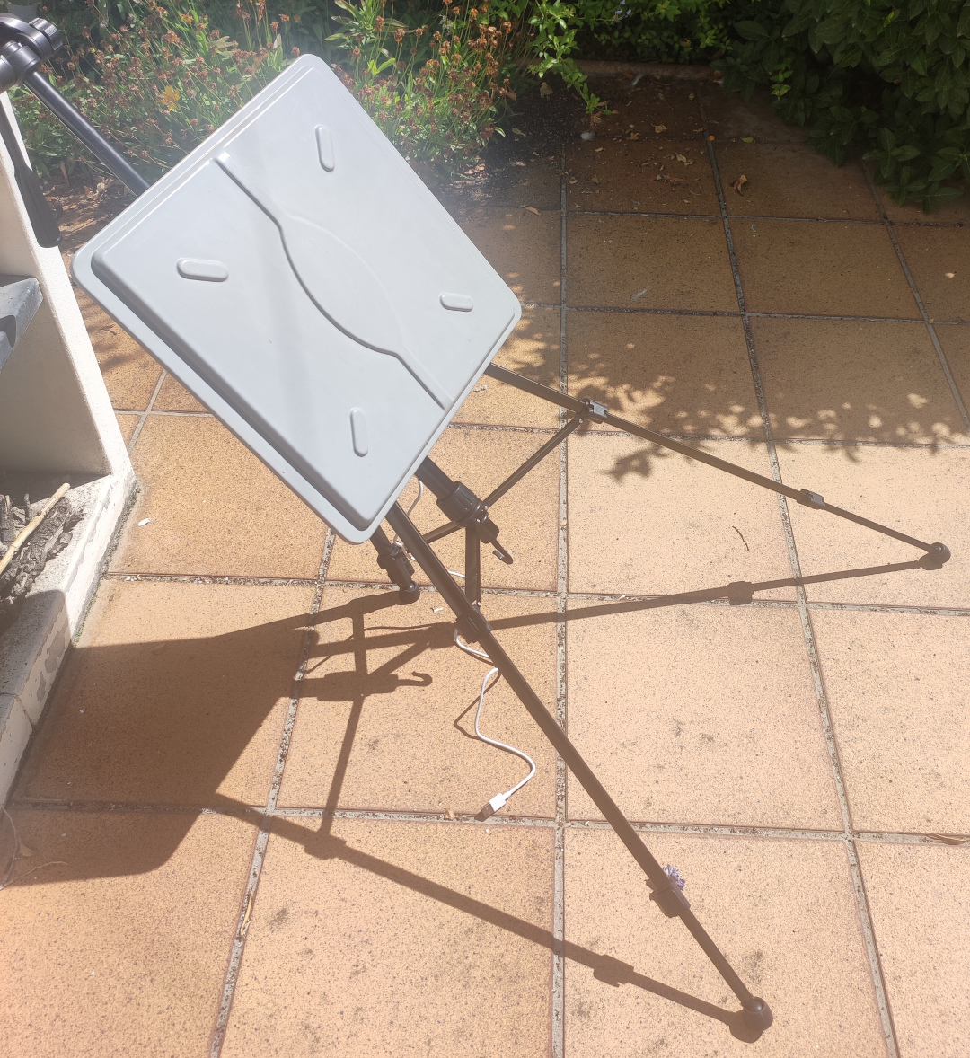
For the uplink station I used a 24 dBi flat-panel antenna that I had around for some WiFi experiments. The antenna is designed for 5 GHz WiFi, but according to the datasheet the C-band uplink frequency used by the transponder is covered, since it is close enough to some WiFi channels at 5.8 GHz. The uplink is circularly polarized, and this antenna has linear polarization, so there is a 3 dB polarization mismatch loss.
I needed a power amplifier to get a reasonable amount of power, so I purchased an SBB5089 + SE5004 amplifier from Aliexpress. These are 5.8 GHz 2W amplifiers that are sold for about 15€. For this price, they might not be great, and they might not really give 2W (perhaps they give 1W, which is okay). Frank is using some of these in his experiments, so I decided to get one too because it’s a great price for a one-off experiment.
The rest of the uplink station is a B205mini, a lab power supply to power the amplifier, and a laptop. The power amplifier is said to have 40 dB of gain, and I can attest that the B205mini has enough drive to saturate it. The power amplifier is powered by 5V USB, but using a lab power supply is handy because it lets me see how much current the amplifier is taking. As the amplifier gets warmer (and it does get really hot indeed), it is quite apparent how the current consumed on transmit drops. Since this most likely means that the gain is dropping with the increase in temperature, and so the output power is dropping too, I increased the USRP gain a little to compensate when this happens. I tried to keep roughly the same current on transmit while running the experiment (speaking from memory, around 900 mA at 5V).
Before running any experiments on the satellite, I did some tests of the power amplifier to get a feeling for how much TX gain I would need in the USRP. I did a two-tone test (with 10 kHz tone separation) and looked at the output of the power amplifier with the same USRP, while monitoring the current consumption of the amplifier. I set an operating point based on third-order intermodulation products. Basically, I increased the gain as far as possible while still having reasonable intermodulation products (20 dB down or so). The TX gain for this was around 73 dB. The maximum TX gain of the B205mini is 89.8 dB, so it can give much more drive than what is needed for this amplifier.
I placed the flat-panel antenna on a camera tripod. Intelsat 37e is at 40.8 deg elevation at my location, so the tripod is placed in a very awkward way when pointing to the satellite. I first set up the antenna pointing by transmitting my two-tone test and looking at the downlink on the remote PC. The next day I waited until the sun was at the same azimuth as Intelsat 37e and checked the shadows, and my azimuth pointing seemed spot on.
For the test of gr4-packet-modem, I decided to use a baudrate of 125 symbols/second based on how much SNR I was getting with the two-tone test. This ended up giving me an Es/N0 of around 9.5 dB, meaning that short uncoded QPSK packets could often be decoded without errors. The link budget is thus that a 22 dBW uplink (polarization losses and the fact that the amplifier probably does less than 2W have already been taken into account) gives around 30.5 dB·Hz CN0 in the downlink. This is on the ballpark of the link budget that Frank gave me for the experiments he had run from ESTEC (Netherlands).
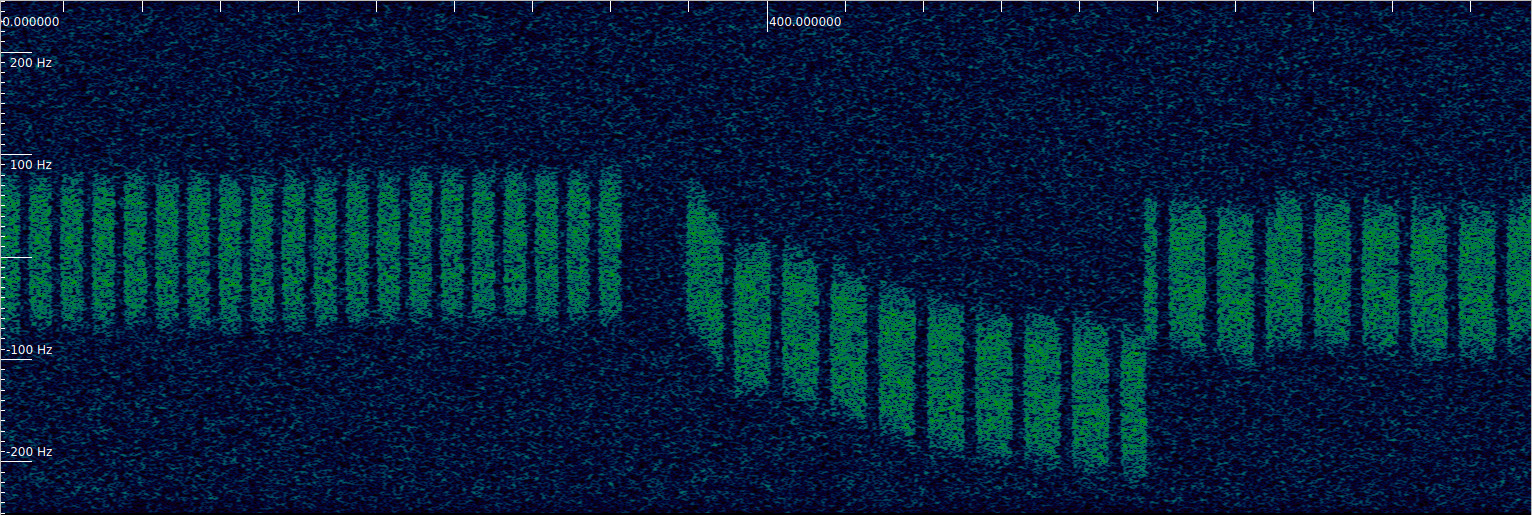
During the test, I found that the frequency instability was much higher than what the default configuration of gr4-packet-modem is prepared to deal with. The signal drifted by hundreds of Hz over the course of a few minutes, so I frequently need retune the receiver manually by looking at the spectrum of the received signal in GNU Radio 3.10. I also needed to increase a lot the frequency search range of the Syncword Detection block and the bandwidth of the Costas Loop in the gr4-packet-modem receiver. So I guess the experiment was not so technically uninteresting in the end, as it provided the chance to test the receiver in very different operating conditions regarding frequency drift compared to all the other tests I have done with this software. The figure below shows a waterfall of the IQ signal recorded at the receiver. The frequency drift is quite clear. There is also a manual retuning visible.
In the remote PC on the teleport I ran a GNU Radio 3.10 flowgraph that decimated the signal to 500 sps (4 samples/symbol, which is what the modem usually runs at), recorded this to an IQ file and also wrote it to a FIFO. The gr4-packet-modem packet_receiver_file application was used to read from the FIFO and decode the data in real time (although latency was quite large at such a low sample rate). The plot_symbols.py script showed constellation plots of each received packet. gr4-packet-modem is normally used with TUN devices on Linux to implement IP communications. In this case I sent ping packets from my laptop in Madrid and received them in the teleport PC. There was no path for the ping replies to be sent back. This was a one-way test only.
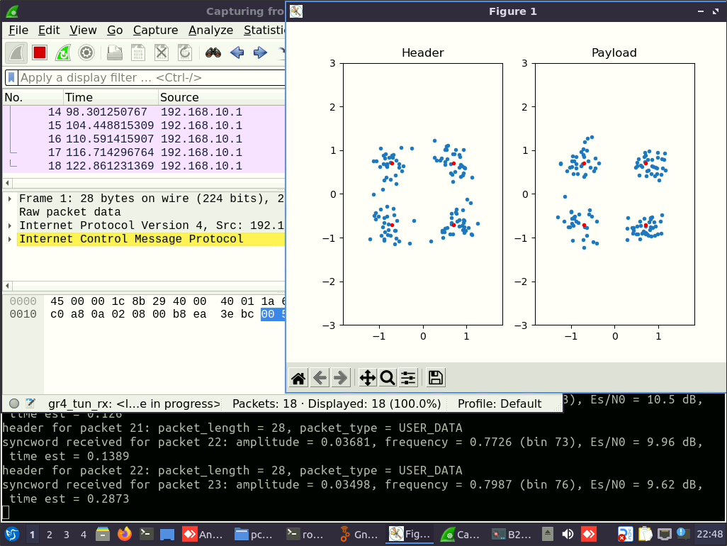
The figure below shows a screenshot of the remote PC during the test. We can see the constellation plot for one packet (which gives evidence that at this SNR there is a reasonable probability of decoding short packets without errors), a Wireshark screen showing the received pings (a ping packet is sent every 6 seconds, since it takes around 4 seconds to transmit at 250 bps), and a terminal with the log of the gr4-packet-modem receiver, which contains Es/N0 estimates.
First I tested transmitting ping packets as short as possible (ping -s 0, which gives 28-byte IPv4 packets). Most of these packets were decoded successfully. Then I tested the normal ping size (which gives 84-byte IPv4 packets). For these the error rate was somewhat higher. The moment when the ping size is changed can be seen in the waterfall shown above.
I have published the IQ recording for this test as the dataset “Test of gr4-packet-modem through an Intelsat 37e C-band transponder” in Zenodo. This recording is already in cf32_le format at 4 samples/symbol, so it can be processed directly by the packet_receiver_file application. However, to get valid decodes it is necessary to increase the frequency search range (which can be done with command line arguments) and the Costas Loop bandwidth (which currently can only be done by editing the values declared in payload_metadata_insert.hpp).
Interesting experiment. With such extremely low symbol rates , how much of the noise is caused by the close in phase noise (up & down converts + satellite) vs the actual link noise?
Looking at the constellation plots I would say that thermal noise dominates, since the noise variance in the amplitude direction is comparable to the noise variance in the phase direction. This depends on how the loop bandwidth is adjusted.
I’ve been building a single-carrier IP modem in C since about May. I kind of lost gusto when it was time to move it to the Raspberry Pi. I think I’m not much of a hardware man anymore… The attraction is QPSK replacing FSK (moving power from carrier to information) and thinking about 10 meters and VHF, as it is 1200 baud. I haven’t tested my Gardner TED yet, so hardware is calling me! Very much enjoyed your blog.
Thanks for the interesting post.
Do you know if the frequency instability from one of the radios, or the satellite transponder itself?
Did you try any lower speed modes, with a lower gain / lower power transmitter? Would something like JT65 work with 0 dBi?
I’ll never forget the first (and only) time I sent and received a signal through a GEO transponder. Seeing a tone appear on my spectrum analyser, that had travelled across the Atlantic, all analog.
I think most of the frequency instability is due to the B205mini that I used for the uplink. I used it with its internal TCXO, so at 5.8GHz the stability is not going to be great. I would expect the satellite transponder to have a stable frequency reference (the kind of stability we see on the QO-100 amateur radio transponder, for instance) and the groundstation at the receive side to be locked to GPS.
I didn’t try other modes or lower power, but it’s possible to estimate the link budget. JT65 and similar modes use SNR in 2.5 kHz bandwidth. The Es/N0 of 9.5 dB that I got in my test at 125 baud corresponds to -3.5 dB in 2.5 kHz. My antenna had around 21 dBi of gain (taking into account polarization losses). So with a 0 dBi antenna you’d get -24.5 dB in 2.5 kHz. That’s just at the margin of what JT65 can decode. So it seems possible, but on the limit.