I wanted to build something easy and useful this summer, so I have gone with a 12V (also adjustable to 13.8V) 5A linear power supply. The design is based on the 12V 15A power supply by Ed WA1TWX that appears in the 2015 ARRL Handbook. The main difference is that I’m using only one pass transistor instead of three. Here I describe my design.
As you can see in the schematic below, the voltage regulator used is the venerable LM723, which drives an external 2N3055 pass transistor. Since the current gain of the 2N3055 can get quite low (perhaps down to 10 or 5) and the LM723 can only source 150mA, a BD239C is used to provide the base current to the 2N3055. The choice of this transistor is not critical. Any small power BJT transistor which is able to pass 1A will do.
The LM723 provides voltage regulation and current limiting. Both of these parameters are adjustable. There is also a crowbar SCR using the TN2015H-6T. The crowbar is triggered on overvoltage using a simple voltage divider. I’ve found this to be a bit troublesome to adjust properly. It would be better to use an IC, such as the MC3423, but sadly this and other similar IC’s are out of production.

In the photo below you can see how I have built the power supply. I’ve used the case from an old computer switching power supply. The AC transformer that I’ve used is a little bit taller than the case, but since the case is made of thin aluminium and can bend a little this is no problem. I’ve also reused the heatsinks from the computer power supply. This were originally mounted on the PCB, but I’ve mounted them to the sides of the case. The left one has the SCR and the current shunt resistor. The right one has the diode rectifier bridge and the BD239C.
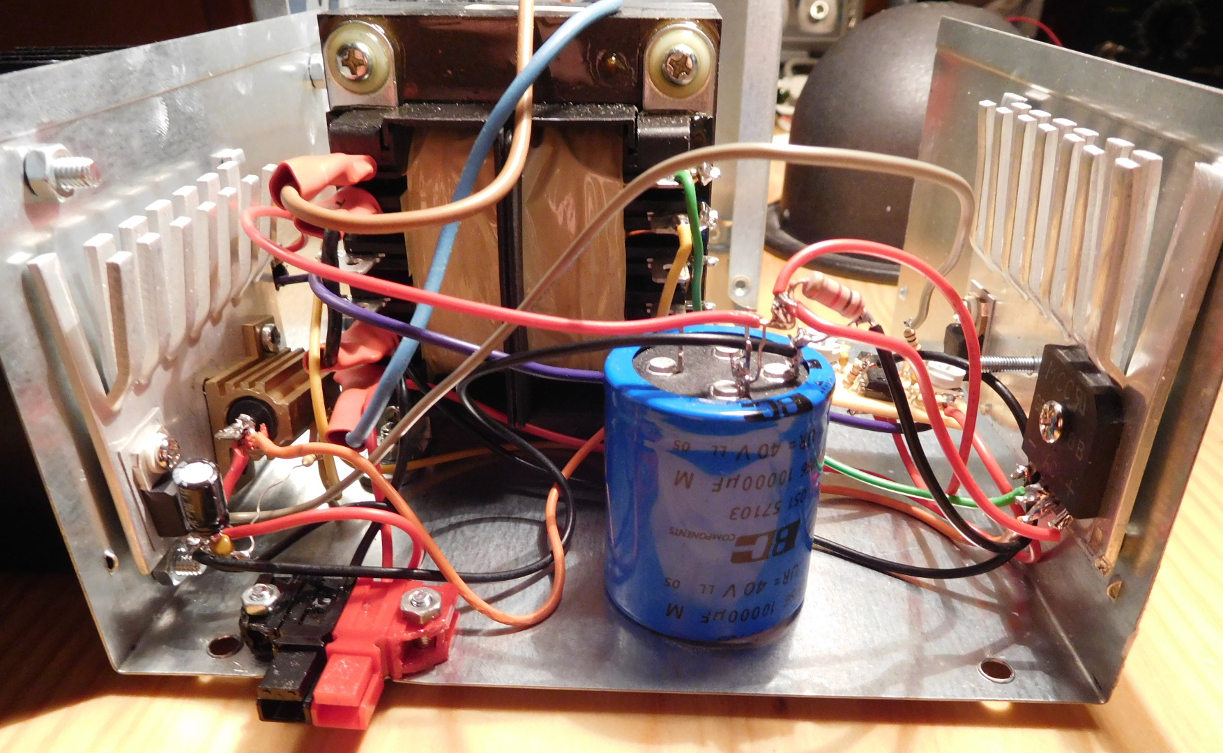
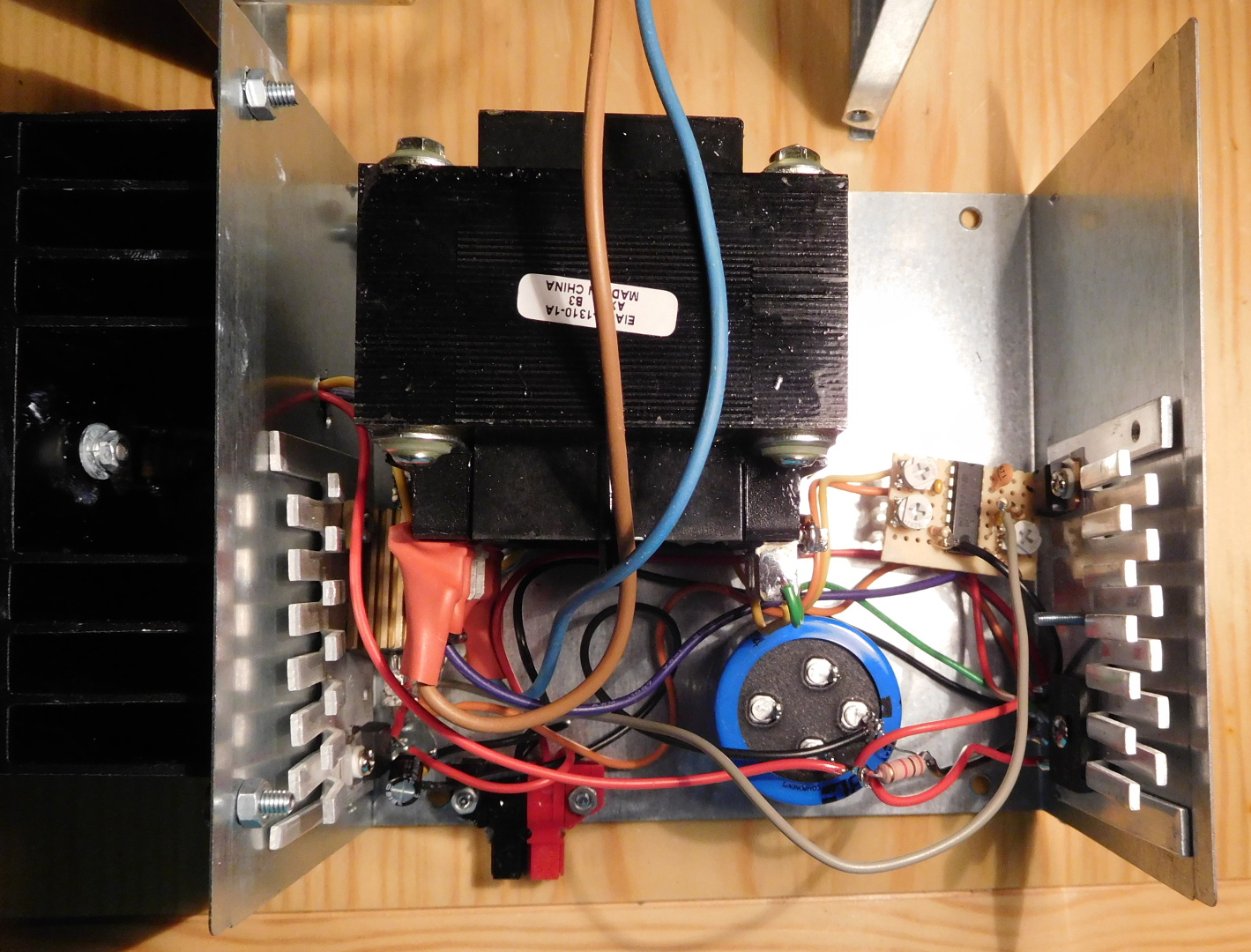
The voltage regulator circuit is mounted on a small perforated prototype board. The three trimmer pots are as follows: the bottom left is the current limit (clockwise is higher current), the bottom right is voltage adjust (clockwise is higher voltage), the top one is the overvoltage trigger point (clockwise is higher trigger point).

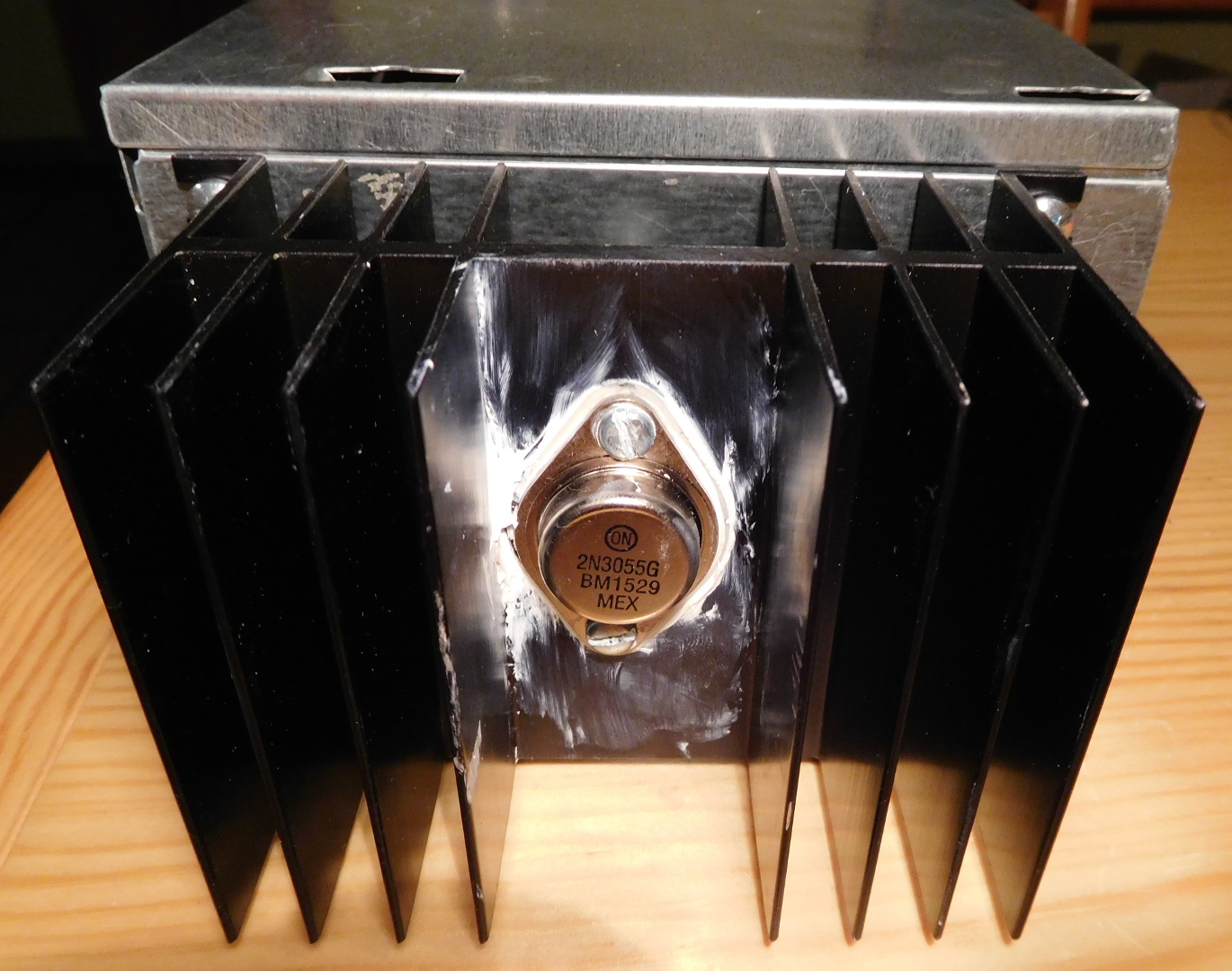
The pass transistor is mounted on a large heatsink. It has a thermal resistance of 1.16ºC/W and can handle up to 50W (with a 58ºC raise). When working at full current, the 2N3055 would drop around 8V at 5A, dissipating 40W of heat. Its junction to case thermal resistance is 1.52ºC/W. The transistor is mounted on the heatsink using a mica insulator and thermal compound. This will have a thermal resistance of around 1 or 2ºC/W. Let’s assume that the junction to air thermal resistance is a total of 4ºC/W. At 40W this corresponds to a temperature raise of 160ºC. If ambient temperature is 30ºC, the junction heats up to 190ºC. This is fine, because the maximum junction temperature of the 2N3055 is 200ºC. The power handling capability of the transistor (which is a maximum of 115W) should be derated according to the case temperature. In our example, the case temperature is 130ºC. This still allows a power dissipation of around 50W.
So the back of the envelope calculations show that thermally speaking, the power supply should work fine. Usually I will be using the supply at much lower currents. Currently, I’m drawing about 1.25A and the transistor case temperature is around 45ºC.
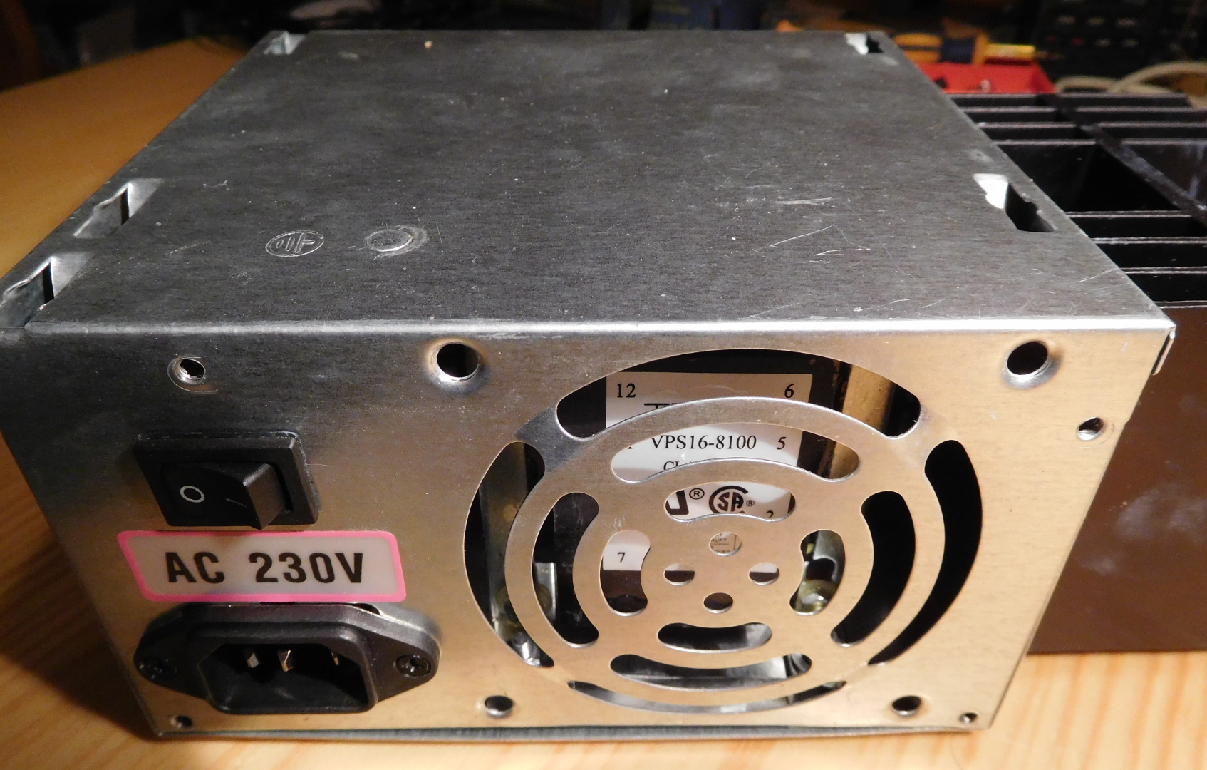
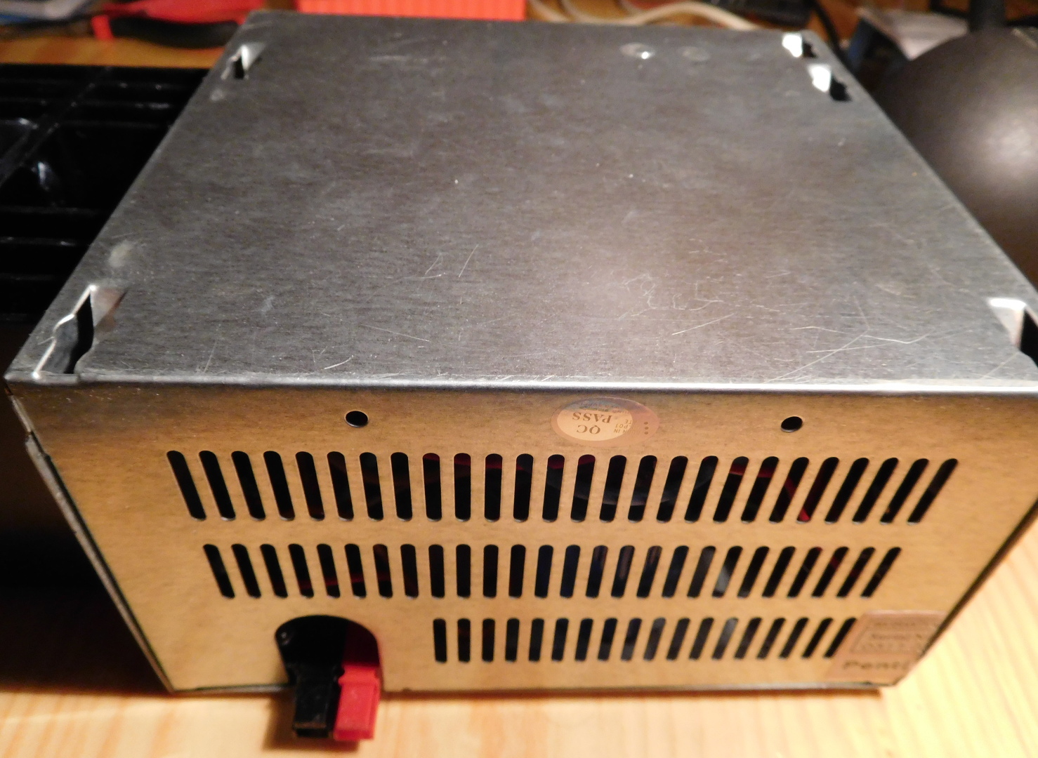
On the back side of the power supply, I’ve replaced the IEC AC connector with a nice filtered one. I’ve reused the power switch.
In the front, I’ve included an Anderson powerpole connector for the output, because this is what I use for all my radios.
Hola Daniel, ¿Puedes decirme para qué sirve la resistencia de 330 Ohm?¿no se calienta?¿No sería adecuado poner un fusible de algo más de 5A en la línea de salida para que cuando actua el SCR deje de actuar el circuito? Muchas gracias por el circuito.
73, EB3BNJ
Hola. La resistencia de 330 Ohm sirve para que el regulador de voltaje tenga siempre alguna carga con una cierta impedancia máxima. No recuerdo los detalles de este regulador de voltaje, pero muchos reguladores de voltaje no funcionan bien si no tienen una carga a la salida o tienen una carga con una impedancia muy alta. La resistencia disipa aproximadamente 1/2 W.
El SCR está principalmente para proteger a la carga de un sobrevoltaje en en caso de que el transistor Q2 fallara en cortocircuito o el regulador de voltaje falle. En este caso el SCR se activa, de modo que la carga estará sujeta a un voltaje muy bajo, y casi toda la corriente circulará por el SCR. Revisando el circuito veo que quizá no sería mala idea reducir el amperaje del fusible F1, ya que en el caso en el que esta condición persista, el SCR estaría disipando aproximadamente los 130 W que puede entregar el transformador (y el fusible F1 deja pasar unos 230 W). En este montaje no creo que el SCR pueda aguantar 130 W indefinidamente, por lo que acabaría fallando también y el problema afectaría a la carga. Creo que el problema es que no tuve en consideración que el diseño del ARRL Handbook está pensado para 120 VAC. Sería más adecuado usar un fusible de 0.5 A.
Hello Daniel, I’m planing copy your project. But It’s been really hard to find a 16V 8A transformer. It’s possible to use a 18V instead?
Regards
PU3YZH
Hi Henrique, it’s possible to use a 18V transformer, but then the transistor Q2 will be dropping more voltage, and will have to dissipate more power, so bear in mind heat dissipation and limits. Maybe you won’t be able to get 5A, but it will work fine at lower current.
Thank you for your answer Daniel. I’m making my power suply with some modifications, like 2 transistor Q2, so I think it will not overheat. other think That I’m planning is changing the resistors and potenciometer for overvoltage adjust for a 15V zenner diode, what do you think?
Hi Henrique, I don’t understand exactly what you mean by using a 15V Zener. Do you plan on removing the SCR as well and using the Zener to shunt all the current if the output goes above 15V?
Acctually, my idea is change the R1, R2 and R3 for the 15V Zener, conected to the SCR gate.
Hey, Daniel. I was wondering if I could have permission to use the photo of your internal schematic for a student project report? I would be using it as an example of a power supply’s internal schematic with similar electrical ratings. Thank you!
Yes. Feel free to use the schematic for your report.