Following the success of my JT4G detector, which I used to detect very weak signals from DSWLP-B and was also tested by other people, I have made a similar detector for the 250baud GMSK telemetry transmissions.
The coding used by the DSLWP-B GMSK telemetry follows the CCSDS standards for turbo-encoded GMSK/OQPSK. The relevant documentation can be found in the TM Synchronization and Channel Coding and Radio Frequency and Modulation Systems–Part 1: Earth Stations and Spacecraft blue books.
The CCSDS standards specify that a 64bit ASM shall be attached to each \(r=1/2\) turbo codeword. The idea of this algorithm is to correlate against the ASM (adequately precoded and modulated in GMSK). The ASM spans 256ms and the correlation is done as a single coherent integration. As a rule of thumb, this should achieve a reliable detection of signals down to around 12dB C/N0, which is equivalent to -12dB Eb/N0 or -22dB SNR in 2500Hz. Note that the decoding threshold for the \(r=1/2\) turbo code is around 1.5dB Eb/N0, so it is much easier to detect the GMSK beacon using this algorithm than to decode it. The difficulty of GMSK detection is comparable to the difficulty of JT4G decoding, which has a decoding threshold of around -23dB SNR in 2500Hz.
Here I explain the details of this GMSK ASM detector. The Python script for the detector is dslwp_gmsk.py.
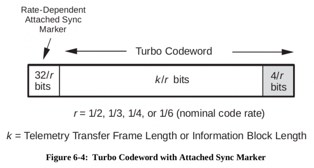
The ASM (attached sync marker) for \(r=1/2\) turbo coded telemetry is specified in Section 9.3.5 of the “TM Synchronization and Channel Coding” blue book as 0x034776C7272895B0 (it should be transmitted left to right, in the order it is written). This 64bit syncword in transmitted before each turbo codeword, as indicated in the figure below.
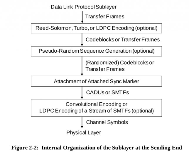
Since DSLWP-B doesn’t use convolutional coding or stream LDPC encoding, the ASM is not encoded any further and it is passed directly as channel symbols to the physical layer, as shown in the figure below.
However, there is a subtlety here. In the physical layer a precoder is used before modulating the channel symbols as GMSK. This precoder is described in the figure below, taken from the “Radio Frequency and Modulation Systems–Part 1: Earth Stations and Spacecraft” blue book.
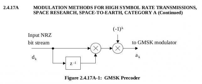
As we shall see, the goal of this precoder is that the symbols \(d_k\) are read directly when the GMSK modulation is interpreted as OQPSK. Indeed, in GMSK, a 1 is transmitted as a phase shift of \(\pi/2\) and a 0 is transmitted as a phase shift of \(-\pi/2\). When this is read as OQPSK, the following happens.
Assume that we are currently sampling the \(I\) branch, so our phase is either \(0\) or \(\pi\), corresponding to \(I=1\) or \(I=-1\) respectively. Then half a symbol period later, the phase gets shifted by \(\pm\pi/2\), corresponding to the transmission of a GMSK bit, and we sample the \(Q\) branch (recall that the symbol rate for OQPSK is half the symbol rate for GMSK). The resulting phase and hence the resulting \(Q\) depends both on the \(I\) we had and on the GMSK bit transmitted.
With a GMSK bit of 1 we either get from \(I = 1\) to \(Q = 1\) or from \(I = -1\) to \(Q = -1\). With a GMSK bit of 0 we get from \(I = 1\) to \(Q = -1\) or from \(I = -1\) to \(Q = 1\). We see that the GMSK bit acts in a differential way. A 1 preserves the value of the \(I\) branch into the \(Q\) branch, and a 0 inverts the value of \(I\) into the \(Q\) branch. When going from \(Q\) to \(I\), the behaviour is opposite: a GMSK bit of 1 gets from \(Q = 1\) to \(I = -1\) or from \(Q = -1\) to \(I = 1\), and a GMSK bit of 0 gets from \(Q = 1\) to \(I = 1\) or from \(Q = -1\) or from \(Q = -1\) to \(I = -1\). So when going from \(Q\) to \(I\), a GMSK bit of 1 inverts and a GMSK bit of 0 preserves the value.
Thus, if we want to read the stream of symbols \(d_k\) directly from the OQPSK demodulation, we should transmit \(a_k = 1 + d_k + d_{k-1}\) when going from \(I\) to \(Q\) and \(a_k = d_k + d_{k-1}\) when going from \(Q\) to \(I\) (here we use arithmetic over \(GF(2)\)). Noting that we go from \(I\) to \(Q\) when \(k\) is even and we go from \(Q\) to \(I\) when \(k\) is odd, we have\[a_k = 1 + k + d_k + d_{k-1},\] for all \(k\), which is exactly the same as it is represented in the figure above.
This precoding for GMSK transmission is not only done for convenience at the receiving side. Without it, the receiver would have to perform some form of differential decoding, since GMSK is inherently differential (bits are transmitted as a change in phase). This differential decoding would propagate bit errors. Therefore, the precoder ensures optimal performance.
Note that when precoding the 64bit ASM, we only get 63 bits. The first bit would depend on the initial state of the precoder (the contents of the \(z^{-1}\) cell), which is undefined. These 63 bits are then shaped with a Gaussian filter. The Gaussian filter implementation is taken from the GNU Radio GMSK modulator, which in turn uses the following Gaussian filter taps.
These Gaussian filter taps follow the Gaussian curve\[a_n = \exp\left(-\frac{2\pi^2\beta^2n^2}{S^2\log{2}}\right),\]where \(\beta\) is the bandwith time product (BT) and \(S\) is the samples per symbol.
Using this formula, a window spanning 4 symbols is obtained, so \(n\) ranges from -2S to 2S-1, and normalized to have an integral of one. This window is then convolved with a square window spanning one symbol to obtain the taps of the symbol filter. The precoded ASM bits are then filtered and upsampled using this filter.
The BT is taken as \(\beta=0.5\) from gr-dswlp. However, the CCSDS recommends a BT of 0.25. It would be interesting to know what is the BT really used by DSLWP-B and see if it can be measured from the high SNR recordings made at Dwingeloo.
After the bits are fitered and upsampled, they are scaled to produce the correct deviation and FM modulated to produce the GMSK modulated ASM. This GMSK signal is then used as a matched filter to correlate with the received signal.
The correlation algorithm goes as follows. The FFT is used to scan in frequency. The FFT size is the size of the GMSK modulated ASM, so all the ASM is integrated coherently. We denote this size by \(N\). A block of \(N\) samples from the signal is taken, multiplied by the complex conjugated of the GMSK modulated ASM, and Fourier transformed. A peak in the FFT would indicate that an ASM is contained in the signal, at the frequency indicated by the FFT peak. Blocks offset by \(T/4\), where \(T\) is the symbol period, are taken to scan in time.
For the situation we have here (a large search both in time and frequency) this approach is better (computationally less expensive) than using the FFT to scan in time and performing FFT shifts to scan in frequency. This algorithm is also very similar to what gr-dslwp does in the “QT GUI FFT Correlator Hier” block to detect the signal and pass coarse frequency and phase estimates to the OQPSK decoder.
To show this algorithm in action, we test it with the recordings from the first VLBI session between Dwingeloo and Shahe. We use the recordings taken at UNIX timestamp 1528604394, which corresponds to 2018-06-10 04:19:54 UTC. The recordings are extracted and converted to complex64 raw files as already did in that post (see the script process_vlbi.sh).
Then, we use sox to lowpass filter and convert the raw files to wav. The lowpass filtering is done to remove interfering signals. The sample rate of 40000kHz is maintained. The correlation algorithm can work with any sample rate that is an interger multiple of 250Hz, so as to have an integer number of samples per symbol. The sox command used for the conversion is as follows.
sox -t raw -e floating-point -b 32 -c 2 -r 40000 dwingeloo_435.raw dwingeloo_435.wav lowpass 1000
The wav files are then processed using
$ dslwp_gmsk.py dwingeloo_435.wav dwingeloo_435 "Dwingeloo 435.4MHz"
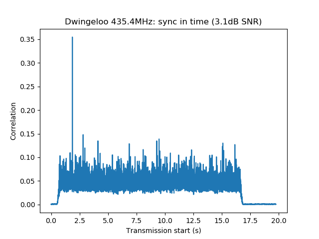
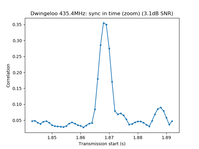
Start time: 1.87s
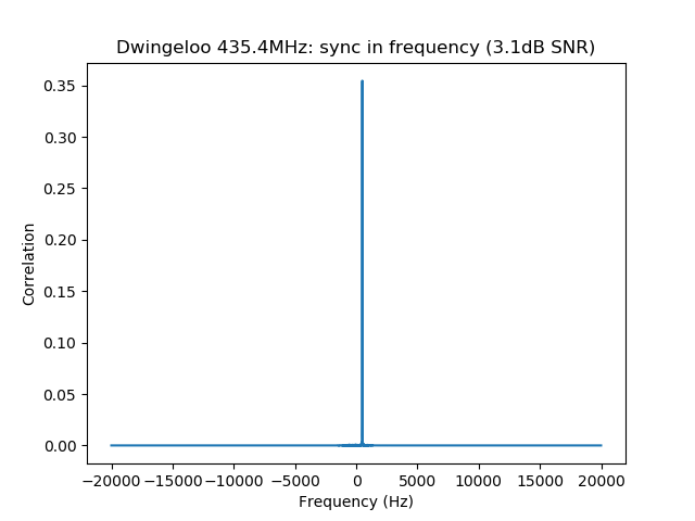
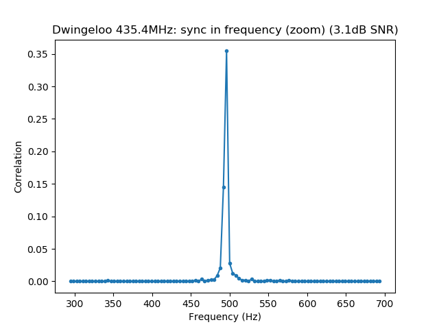
Frequency: 496.0Hz
CN0: 37.1dB, EbN0: 13.1dB, SNR (in 2500Hz): 3.1dB

$ dslwp_gmsk.py dwingeloo_436.wav dwingeloo_436 "Dwingeloo 436.4MHz"
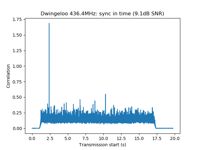
Start time: 2.39s
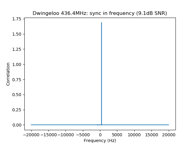
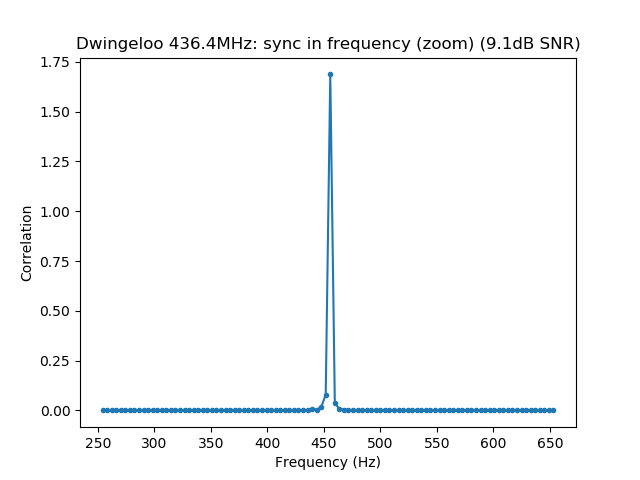
Frequency: 455.6Hz
CN0: 43.1dB, EbN0: 19.1dB, SNR (in 2500Hz): 9.1dB

$ dslwp_gmsk.py dwingeloo_435.wav shahe_435 "Shahe 435.4MHz"
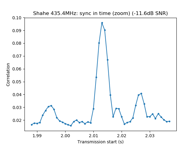
Start time: 2.01s
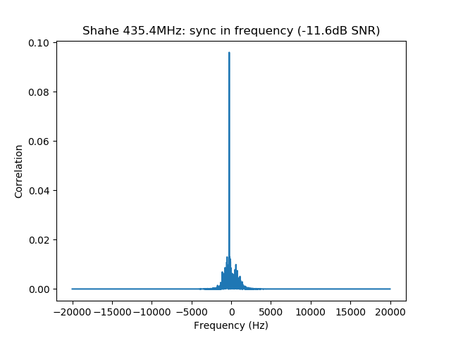
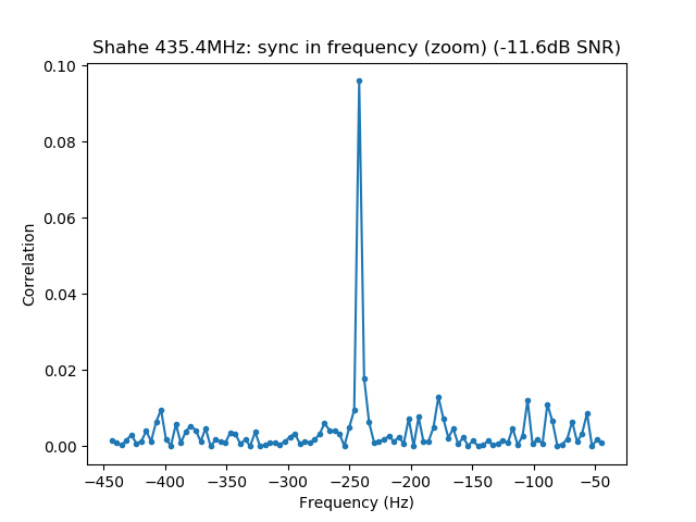
Frequency: -241.9Hz
CN0: 22.4dB, EbN0: -1.6dB, SNR (in 2500Hz): -11.6dB

$ dslwp_gmsk.py dwingeloo_436.wav shahe_436 "Shahe 436.4MHz"
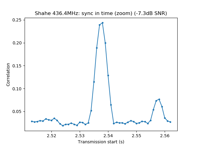
Start time: 2.54s
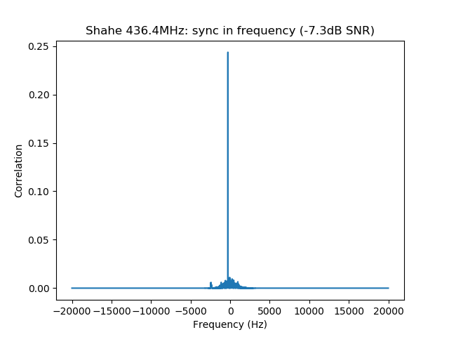
Frequency: -282.3Hz
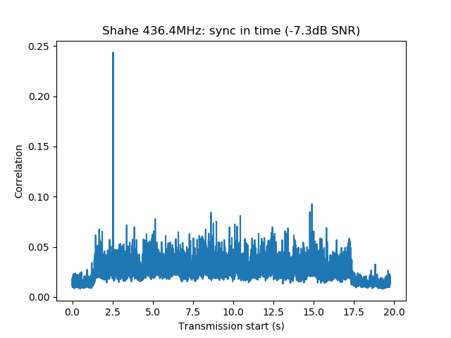
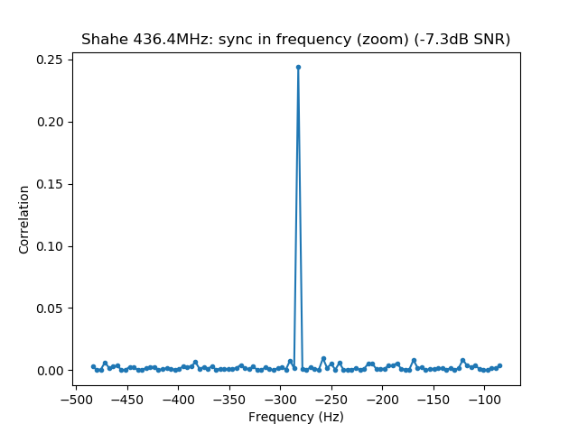
CN0: 26.7dB, EbN0: 2.7dB, SNR (in 2500Hz): -7.3dB
We can observe several interesting details from the results of these correlations. First, note that the 435.4MHz signal is seen roughly 0.52s before the 436.4MHz both in Dwingeloo and Shahe. As I already commented in the the VLBI experiment post, the transmissions in both bands are not synchronized precisely and the data transmitted is different.
Second, in Dwingeloo we observe a difference of 6dB between the 435.4MHz signal and the 436.4MHz signal, while in Shahe the difference is only 4dB. The reason for the difference between both bands was already explained in the VLBI experiment. It is due to the orientations of the antennas used by DSLWP-B in each band. The fact that the difference in Dwingeloo is 6dB while in Shahe is 4dB could be explained because the performance of the receivers might be different for each of the two bands.
Last but not least, the observed frequencies in each band don’t match what would be caused by the Doppler or frequency offset of the DSLWP-B clock if both transmit frequencies are derived from the same oscillator. Indeed, for 1kHz of offset (either Doppler or clock offset), the difference between both bands should be 2Hz, which is less than the frequency resolution using this algorithm. Thus, we should expect to see the same frequency in both bands. However, in both groundstations we observe a difference of roughly 40Hz, the 435.4MHz band being higher in frequency.
The only reasonable explanation for this is that each transmitter has its own independent clock, and the 435.4MHz transmitter is 40Hz (92ppb) higher than the 436.4MHz transmitter. I think that nobody has observed this before. I had already observed that both transmitters are around 200Hz lower than the published frequency, but it turns out that there is also a difference between both transmitters. It will be interesting to monitor this difference and see if and how it evolves with time.
The images produced by the detection script can be seen below. It is interesting to note that the whole packet can be seen in the time correlations, since the cross-correlation of the ASM with the rest of the packet is higher than with the background noise. This is best seen in the Dwingeloo high-SNR recordings and it shows that the ASM is not transmitted immediately at the beginning of the packet. There are about 1.5 seconds of GMSK data before the ASM. I don’t know what is this data. Perhaps it is just a preamble to aid receiver synchronization, although correlation against the ASM as done in gr-dslwp should be enough. In principle no preamble is needed.


One comment