On last Saturday’s V-UHF contest I observed reduced output power on the 70cm band in my FT-817ND. I spent the next day poking inside the radio with the oscilloscope trying to see where the problem was. While doing this, at some point I completely lost output power in all bands. I found that the problem was that F1002, an SMD fuse, had gone open. Here I describe said fuse and the replacement procedure, which I found much easier than I thought.
As you can see in the schematic below, F1002 is connected between J1015, a board-to-board connector that goes to the PA board, and the trace marked in red, which runs almost directly to the DC input and battery connector. The purpose of J1015 is to provide 13V to the PA board. Hence, no wonder that with F1002 open the PA didn’t work at all. This fuse is there so that it will blow if something goes terribly wrong in the PA board, in order to prevent further damage. According to the FT-817ND service manual I have, F1002 is installed only in lots 75 and later. In previous lots, the red trace runs directly from the line filter T1035 to the connector J1015 without any fusing. One should be a bit careful with this version of the service manual, as it is rather old (copyright 2005). In fact, my FT-817ND is marked with lot 35 (third and fourth digits in the serial number), so probably they ran out of lots numbers at some point and started again. I have been unable to locate a newer version of the service manual.
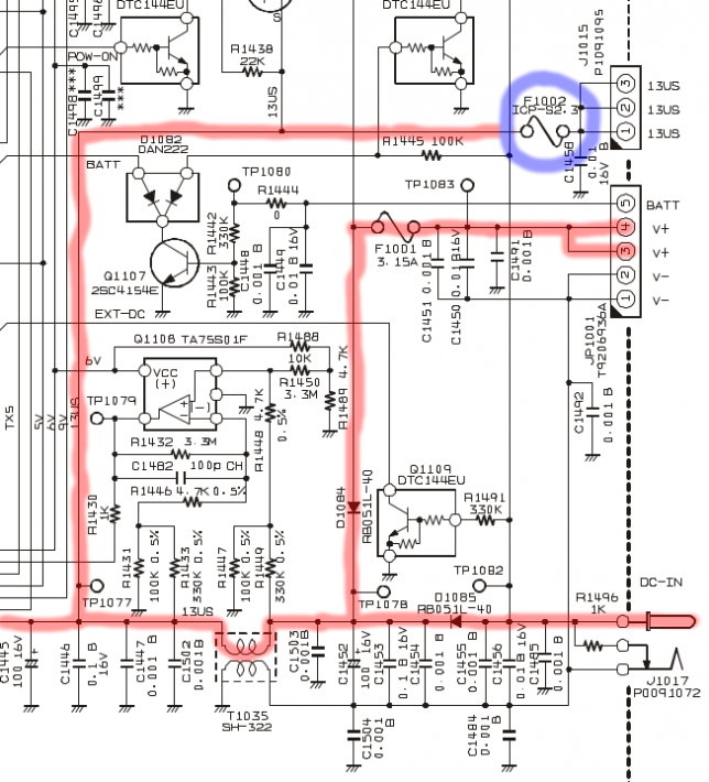
F1002 is a Rohm semiconductor ICP-S2.3TN circuit protector. This is a 2.3A SMD fuse designed to blow quickly and protect ICs and related circuits. The manufacturer gives a typical internal resistance of 0.026Ω and the fuse is rated up to 50V.
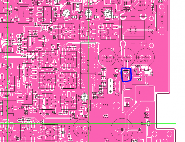
The picture below marks the location of F1002 on the PCB. It is easy to spot, as J1001 and J1002 are the coaxial connectors with pigtails running down to the PA board for the RX and TX paths respectively. To access the component more easily, it is better to disconnect these pigtails. This is achieved by pulling carefully.
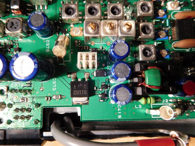
The picture below shows F1002 with the pigtails already disconnected.
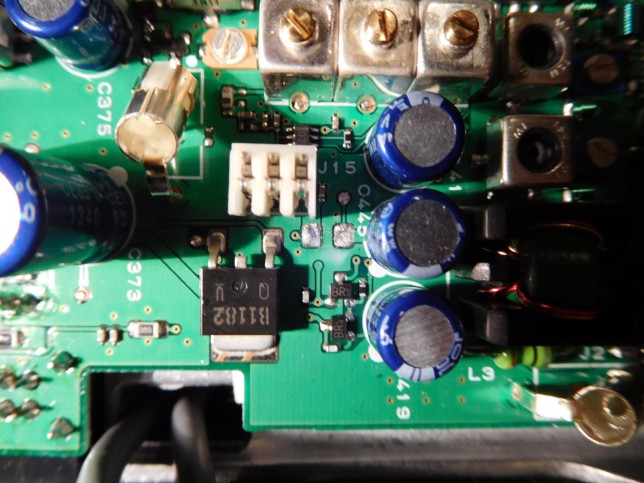
Removing the component was much easier than expected. Since this fuse conducts a fair amount of current, the traces are large and act as a good heatsink, one has to use high temperatures on the soldering iron. Then one risks damaging the PCB if things are not done carefully. I used the technique of heating alternatively each of the pads with the soldering iron tip while pulling gently with some tweezers. First one of the pads came loose and then the second one. After removing the fuse, I tried to reflow the solder remaining on the pads to leave a smooth surface, but it needed very high tip temperatures. As you can see in the picture below, the result was quite nice.
It seems that the ICP-S2.3TN is quite hard to get, even in large quantities, as it is obsolete and out of production. I decided that almost any SMD fuse would serve as a replacement, and I wanted to fix this problem as soon as possible, so I looked at what SMD fuses my local electronic store had in stock. I decided for the 1206SFF200F/63. This is a 2A fuse in a 1206 footprint. I eyeballed that a 1206 component would fit nicely and the lower current rating shouldn’t be much of a problem. The voltage rating for this fuse is 63V and its resistance is 0.050Ω. It also blows as fast as the ICP-S2.3TN. It’s not the perfect replacement, but it can do the job.
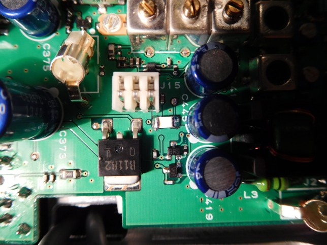
The picture below shows the new fuse soldered in place. It is an ugly, unmarked component. To solder it, I used the technique of tacking one pad, then soldering the other one, and finally applying more solder to the first pad. It was quite hard to get the solder to flow and high temperatures were needed. I used the help of large amounts of flux, which not only helps the solder flow, but it also helps transmit heat when it starts boiling. Finally, I cleaned the area with isopropanol and a cotton swab.
I don’t know why this fuse went open. It is possible that while poking around with the oscilloscope probe, I shorted something accidentally. However, the fused 13V net is only present in the main board in this fuse and in the connector J1015. Then it runs off to the PA board, which was covered with the bottom case. Hence, I think it is unlikely that I shorted this 13V net to ground, as I wasn’t probing anywhere near J1015 and I didn’t notice anything weird.
After replacing the fuse, the problem of reduced power output in the 70cm band still persists. However, I think I just need to do a software calibration and increase the TX gain in this band a little. I need a power meter to do this properly, so I will talk about it in a future post.
Thanks, I have used your clear explanation on another circuit board with the same fuse. Seems that 7th generation Honda (car) radio boards commonly blow the exact same fuse. I also picked up the replacement fuse you specified. The Honda community is not aware of this option because of the scarcity of the ICP-S2.3TN and is bypassing the blown fuses as the general workaround. I assume the replacement fuse is safer than no fuse at all in position. I will link this article on forums discussing the problem.
Thanks again.
Hi Mario, the ICP-S2.3TN fuse seems quite hard to get. However, it can be replaced by almost any SMD fuse of a similar current rating in a 1206 metric footprint or other footprint of a compatible size. The 1206SFF200F/63 was just the cheapest option that my local store had in stock. I’m sure there are many other possible replacements.
I would never replace a blown fuse by a direct short. Fuses are usually installed for the important reason of protecting the circuit. Without a fuse you risk damaging expensive equipment.
I have an FT-817 that will not power up. I felt like I had this resolved when i saw the circuit board pictorial but soon discovered on my circuit board there are no fuses where this fuse is shown so Yaesu must have done a board change. Every component is exactly as shown on the pictorial but the dog gone fuse is simply not there?
Dear Randy,
A couple comments: As you can see in the post, that fuse was only installed in lots 75 and later. Your board is probably a previous lot without the fuse.
The fuse is used to power the PA board. If the fuse goes open, the radio still powers on and receives correctly. If your radio doesn’t power on at all, then your problem doesn’t have anything to do with this fuse.
I hope this helps.
For Randy: I suggest to verify D1085 on the primary power or try to supply by the internal battery
Very clear explanation, thank you.
Daniel, A big thanks for posting this. My FT-817ND had no output for the last 2 years. I have other radios so I just stopped using the 817 until last night. I thought I’d do a web search on possible fixes. Your post came up an describes exactly what my radio was doing. 15 minutes of finding screwdrivers, disassembly, soldering a new fuse (mine is also a random 2A SMD) and re-assembly and my radio is back to 100%!