In my previous post I decoded a transmission from a V16 beacon. The V16 beacon has mandatorily replaced warning triangles in Spain in 2026. It is a device that contains a strobe light and an NB-IoT modem that sends its GNSS geolocation using the cellular network. It is said that the beacon first transmits is geolocation 100 seconds after it has been powered on, and then it transmits it again every 100 seconds. In that post I recorded one of those transmissions done after the beacon had been powered on for a few minutes and I decoded it by hand. I showed that the transmission contains a control plane service request NAS message that embeds a 158 byte encrypted message, which is what presumably contains the geolocation and other beacon data.
In that post I couldn’t show how the beacon connects to the cellular network and sets up the EPS security context used to encrypt the message, since that would have happened some minutes before I made the recording. I have now made a recording that contains both the NB-IoT uplink and the corresponding NB-IoT downlink and starts before the V16 beacon is switched on. In this post I show the contents of the uplink recording.
Recording set up
In the previous post I determined that the beacon transmits on 832.3 MHz, which is the NB-IoT uplink in the B20 band for Orange. The corresponding downlink frequency is 791.3 MHz. Luckily the FDD duplex spacing the B20 band is only 41 MHz, so a 61.44 Msps SDR can be used to record both channels simultaneously. In this case I have used a USRP B205mini.
A problem of recording the B20 band with devices based on the AD936x chips is that the LO frequency is around 800 MHz, so the third harmonic falls around 2.4 GHz. Because the LO is a square wave, it is quite common for WiFi and other 2.4 GHz signals to show up in the B20 recording. When recording a single channel, some clever adjustment of the LO frequency can move the 2.4 GHz interference away from the channel of interest. However, when recording these two NB-IoT channels, this is more difficult.
To improve the quality of the recording, I made a ground plane antenna similar to the one that I made for recording DME signals, and I added a coax stub to this antenna to serve as a notch filter for 2.4 GHz. I selected 818 MHz as the LO frequency. With all this, there is little to none interference in the downlink channel and some weaker WiFi signals occasionally in the uplink channel (which is not really a problem, because the V16 beacon uplink is very strong).
I also set up the beacon differently compared to the previous recording. In the previous recording I placed the beacon on a window that faces the nearest cell tower. Placing the beacon on a window rather than testing indoors is because I assume that the beacon needs to have direct view of the sky to get a good GNSS fix. For this recording, I set the antenna and SDR on that window, to get good SNR on the downlink signal. To prevent the V16 beacon from saturating the receiver, I placed the beacon on the window on the opposite side of the house. This is about 12 meters away from the receiving antenna with an almost line of sight path. The attenuation is high enough that the V16 beacon does not saturate the receiver when it is set to a gain that is reasonable for the NB-IoT downlink signal.
I used a GNU Radio flowgraph to receive IQ data at 61.44 Msps from the USRP, downconvert each of the two channels to baseband, downsample them to 320 ksps, and record to disk. I recorded in GNU Radio metadata format in order to have rx_time tags from the USRP. I set the USRP to the PC clock (which was synchronized with NTP) without using a PPS signal, so the recording timestamps should be accurate to within a few ms.
I started the recording at 11:44:19 UTC, and then I waited until 11:45:00 UTC to turn on the V16 beacon. I timed this using my watch, which I had synchronized by hand to the PC clock, so the switch on time of the V16 beacon should be accurate to within one or two seconds.
Waterfall analysis
By looking at the waterfall of the recording in Inspectrum we can already get some good information about how the beacon works. The beacon first transmits 40 seconds after being switched on. There is an NPRACH followed by a bunch of NPUSCH transmissions. Below we will see that this corresponds to the initial connection to the cell network.
After 22 seconds we see another transmission, which only contains two NPUSCH. We will see that what happens here is that the eNB sends the beacon an RRC connection release because of inactivity. The beacon is just acknowledging that message.
Roughly 100 seconds after the first transmission, there is another transmission. The waterfall of this looks quite similar to the waterfall of the recording I used in the previous post. This is because this is the same kind of transmission of a control plane service request NAS message. We can also note that the NPRACH sequence used here is different (and longer) than the one used in the first transmission.
After 22 seconds there is another short transmission of two NPUSCH that corresponds to the acknowledgement of the RRC connection release because of inactivity.
This process repeats approximately every 100 seconds. There is another transmission that looks very similar to this third transmission (it is not identical because the eNB sometimes schedules things slightly differently), and 22 seconds later there is the acknowledgement of the RRC connection release. The recording ends here after 342 seconds, but I assume that the beacon would have continued sending control plane service request NAS messages every 100 seconds and being timed out 22 seconds later.
Decoding
To decode the NPUSCH transmissions in the uplink I have used the same code and procedures as in the previous post, so I will not repeat the details here. I will only mention the things that are different or interesting.
The first thing to note is that the physical cell ID is different. I quickly realized this when I saw that the Hadamard vector \(w_u(n)\) used in the NPUSCH format 2 DMRS was different. This depends on \(u = N^{\mathrm{Ncell}}_{\mathrm{ID}}\ \operatorname{mod} 16\). Whereas in the previous recording \(N^{\mathrm{Ncell}}_{\mathrm{ID}} = 145\), I found that in this recording \(N^{\mathrm{Ncell}}_{\mathrm{ID}} = 261\). The two recording have been made 1.5 months apart, and I don’t think that the cell IDs have been renumbered. I suspect that since the beacon was placed in a different window, it decided to connect to a different eNB. I have not looked at the downlink recording yet, but I am somewhat concerned that it might contain the downlink signal of \(N^{\mathrm{Ncell}}_{\mathrm{ID}} = 145\) with much higher SNR than that of \(N^{\mathrm{Ncell}}_{\mathrm{ID}} = 261\), which is the cell that I would need to see what the beacon is receiving on the downlink.
Another difference is that the first NPUSCH format 1 transmission in this recording is only one resource unit long. In the previous post, the first NPUSCH transmission was 6 resource units long. We saw that it was composed by 2 repetitions of a 3 resource unit transport block. Using MCS 1, this gave a transport block size of 88 bits, which is the appropriate for the NB-IoT RRC connection request message. Here it turns out that the transmission uses MCS 6. With one resource unit this also gives a transport block size of 88 bits. However the coding rate for MCS 6 is higher than 1/3, so the rate matching algorithm does not repeat any Turbo codeword bits. This means that we cannot use rate matching repetitions to find the RNTI. Therefore, to find the RNTI we attempt to decode the transport block and check the CRC. The CRC check will only be successful for the correct RNTI. As in the previous post, we use the scrambling sequence from an NPUSCH format 2 transmission to narrow down the set of RNTI candidates.
Since the UE is assigned a different RNTI every time that it transmits NPRACH after having being released from the RRC because of inactivity, we need to repeat this search for each time.
Once we have obtained synchronization to the cell frame and subframe structure, we can propagate this synchronization by counting samples in the IQ recording. This count occasionally slips by one subframe when propagating long intervals, due to the sampling frequency offset. However it is easy to notice and correct the slip because many scrambling sequences and DMRS sequences depend on the slot number.
Decoding is just a matter of selecting the start subframe, duration and occupied subcarriers for each transmission by looking at the Inspectrum waterfall, doing some small guesswork to find the MCS, and finding the RNTI after each NPRACH.
MAC layer PDUs
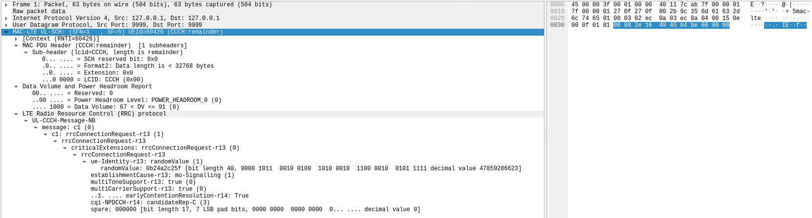
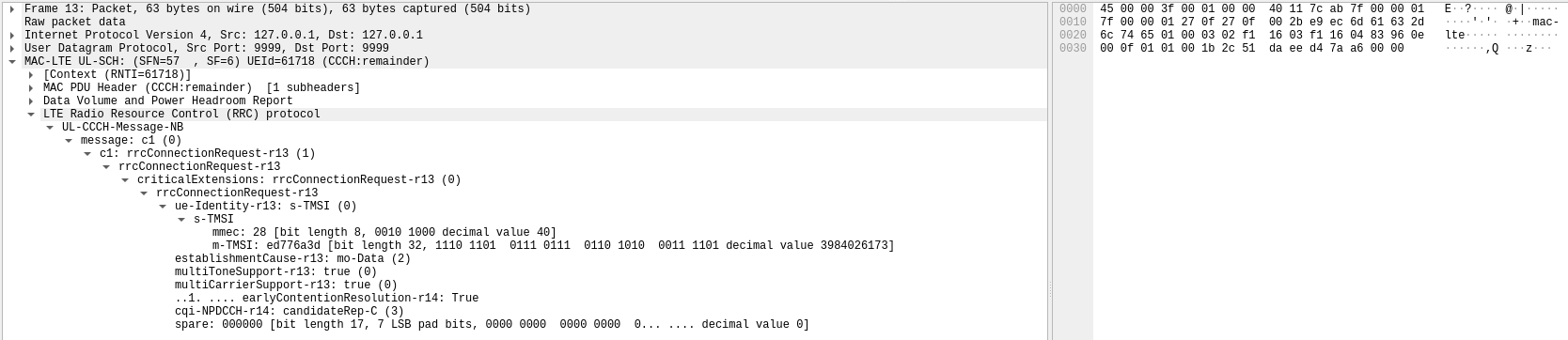
In this section I analyse the decoded MAC PDUs in Wireshark. The first PDU is the initial RRC connection request transmitted after the first NPRACH. This RRC connection request is similar to the one we had seen in the previous post, but there are some differences. First, the UE identity uses a random value rather than an S-TMSI. This is because the UE has not been assigned a TMSI by the network yet. Recall that the UE identity in this message is only used for contention resolution. The establishment cause is mo-Signalling rather than mo-Data. This makes sense, because in this moment the V16 beacon wants to register to the network rather than to send any data. Finally, the cqi-NPDCCH-r14 field contains a value of candidateRep-C (in the previous post it contained “no measurements”). The values of this field are defined in Table 9.1.22.15-1 in TS 36.133. The value of candidateRep-C given here means that the UE believes that it needs 4 NPDCCH repetitions to achieve a decoding error rate lower than 1%. Also, the data volume report indicates that the UE only has between 68 and 91 bytes to send.
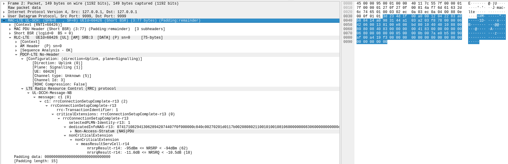
The next PDU that the UE transmits is an RRC connection setup complete message that contains a NAS PDU with and attach request NAS message and a PDN connectivity request ESM message. This is the beacon registering to the network. In addition, the RRC connection setup complete contains signal quality measurements of the serving cell: an NRSRP of around -95 dBm and NRSRQ of -11 dB.
The dissection of the NAS PDU is given here. We can see that it contains the IMSI of the V16 beacon (214032698247044) and that it states that the UE supports the control plane CIoT EPS optimization.
Non-Access-Stratum (NAS)PDU
    0000 .... = Security header type: Plain NAS message, not security protected (0)
    .... 0111 = Protocol discriminator: EPS mobility management messages (0x7)
    NAS EPS Mobility Management Message Type: Attach request (0x41)
    0... .... = Type of security context flag (TSC): Native security context (for KSIasme or KSIamf)
    .111 .... = NAS key set identifier: No key is available (7)
    .... 0... = Spare bit(s): 0x00
    .... .001 = EPS attach type: EPS attach (1)
    EPS mobile identity
        Length: 8
        .... 1... = Odd/even indication: Odd number of identity digits
        .... .001 = Type of identity: IMSI (1)
        IMSI: 214032698247044
        [Association IMSI: 214032698247044]
            Mobile Country Code (MCC): Spain (214)
            Mobile Network Code (MNC): France Telecom España, SA (03)
    UE network capability
        Length: 7
        1... .... = EEA0: Supported
        .1.. .... = 128-EEA1: Supported
        ..1. .... = 128-EEA2: Supported
        ...1 .... = 128-EEA3: Supported
        .... 0... = EEA4: Not supported
        .... .0.. = EEA5: Not supported
        .... ..0. = EEA6: Not supported
        .... ...0 = EEA7: Not supported
        1... .... = EIA0: Supported
        .1.. .... = 128-EIA1: Supported
        ..1. .... = 128-EIA2: Supported
        ...1 .... = 128-EIA3: Supported
        .... 0... = EIA4: Not supported
        .... .0.. = EIA5: Not supported
        .... ..0. = EIA6: Not supported
        .... ...0 = EPS-UPIP: Not supported
        0... .... = UEA0: Not supported
        .0.. .... = UEA1: Not supported
        ..0. .... = UEA2: Not supported
        ...0 .... = UEA3: Not supported
        .... 0... = UEA4: Not supported
        .... .0.. = UEA5: Not supported
        .... ..0. = UEA6: Not supported
        .... ...0 = UEA7: Not supported
        0... .... = UCS2 support (UCS2): The UE has a preference for the default alphabet
        .0.. .... = UMTS integrity algorithm UIA1: Not supported
        ..0. .... = UMTS integrity algorithm UIA2: Not supported
        ...0 .... = UMTS integrity algorithm UIA3: Not supported
        .... 0... = UMTS integrity algorithm UIA4: Not supported
        .... .0.. = UMTS integrity algorithm UIA5: Not supported
        .... ..0. = UMTS integrity algorithm UIA6: Not supported
        .... ...0 = UMTS integrity algorithm UIA7: Not supported
        0... .... = ProSe direct discovery: Not supported
        .0.. .... = ProSe: Not supported
        ..0. .... = H.245 After SRVCC Handover: Not supported
        ...0 .... = Access class control for CSFB: Not supported
        .... 1... = LTE Positioning Protocol: Supported
        .... .1.. = Location services (LCS) notification mechanisms: Supported
        .... ..0. = SRVCC from E-UTRAN to cdma2000 1xCS: Not supported
        .... ...0 = Notification procedure: Not supported
        1... .... = Extended protocol configuration options: Supported
        .0.. .... = Header compression for control plane CIoT EPS optimization: Not supported
        ..0. .... = EMM-REGISTERED w/o PDN connectivity: Not supported
        ...0 .... = S1-U data transfer: Not supported
        .... 0... = User plane CIoT EPS optimization: Not supported
        .... .1.. = Control plane CIoT EPS optimization: Supported
        .... ..0. = ProSe UE-to-network relay: Not supported
        .... ...0 = ProSe direct communication: Not supported
        0... .... = Signalling for a maximum number of 15 EPS bearer contexts: Not supported
        .0.. .... = Service gap control: Not supported
        ..0. .... = N1 mode for 3GPP access: Not supported
        ...0 .... = Dual connectivity with NR: Not supported
        .... 1... = Control plane data backoff: Supported
        .... .1.. = Restriction on use of enhanced coverage: Supported
        .... ..0. = V2X communication over PC5: Not supported
        .... ...0 = Multiple DRB: Not supported
    ESM message container
        Length: 39
        ESM message container contents: 0201d0117b00208080211001010010810600000000830600000000000d00001000000a00001600
            0000 .... = EPS bearer identity: No EPS bearer identity assigned (0)
            .... 0010 = Protocol discriminator: EPS session management messages (0x2)
            Procedure transaction identity: 1
            NAS EPS session management messages: PDN connectivity request (0xd0)
            0001 .... = PDN type: IPv4 (1)
            .... 0001 = Request type: Initial request (1)
            Extended protocol configuration options
                Element ID: 0x7b
                Length: 32
                [Link direction: MS to network (0)]
                1... .... = Extension: True
                .... .000 = Configuration Protocol: PPP for use with IP PDP type or IP PDN type (0)
                Protocol or Container ID: Internet Protocol Control Protocol (0x8021)
                    Length: 0x10 (16)
                    PPP IP Control Protocol
                        Code: Configuration Request (1)
                        Identifier: 1 (0x01)
                        Length: 16
                        Options: (12 bytes), Primary DNS Server IP Address, Secondary DNS Server IP Address
                            Primary DNS Server IP Address
                                Type: Primary DNS Server IP Address (129)
                                Length: 6
                                Primary DNS Address: 0.0.0.0
                            Secondary DNS Server IP Address
                                Type: Secondary DNS Server IP Address (131)
                                Length: 6
                                Secondary DNS Address: 0.0.0.0
                Protocol or Container ID: DNS Server IPv4 Address Request (0x000d)
                    Length: 0x00 (0)
                Protocol or Container ID: IPv4 Link MTU Request (0x0010)
                    Length: 0x00 (0)
                Protocol or Container ID: IP address allocation via NAS signalling (0x000a)
                    Length: 0x00 (0)
                Protocol or Container ID: APN rate control support indicator (0x0016)
                    Length: 0x00 (0)
    Additional update type
        1111 .... = Element ID: 0xf-
        .... 01.. = Preferred CIoT network behaviour: Control plane CIoT EPS optimization (1)
        .... ..0. = SAF: Keeping the NAS signalling connection is not required after the completion of the tracking area updating procedure
        .... ...1 = AUTV: SMS only
    MS network feature support
        1100 .... = Element ID: 0xc-
        .... 000. = Spare bit(s): 0
        .... ...1 = Extended periodic timers: MS supports the extended periodic timer in this domain
    GPRS Timer 2 - T3324 value
        Element ID: 0x6a
        Length: 1
        GPRS Timer: 1 min
            001. .... = Unit: value is incremented in multiples of 1 minute (1)
            ...0 0001 = Timer value: 1
    GPRS Timer 3 - T3412 extended value
        Element ID: 0x5e
        Length: 1
        GPRS Timer: 80 hours
            010. .... = Unit: value is incremented in multiples of 10 hours (2)
            ...0 1000 = Timer value: 8
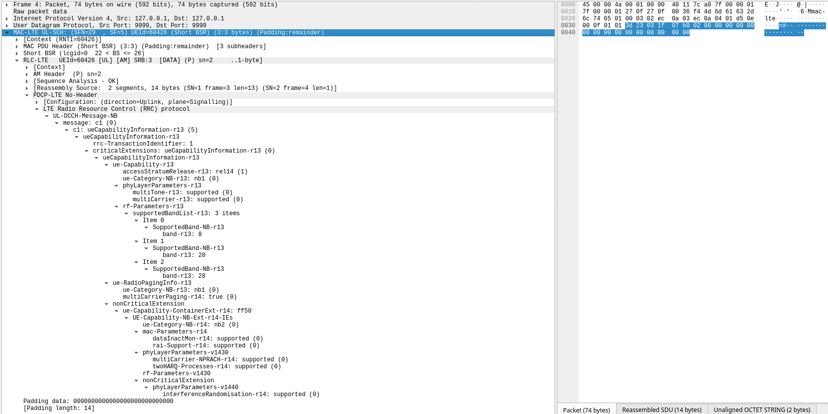
The next message is a UE capability information message. It is fragmented into two AM PDUs, since the first uplink grant was not large enough to transmit this message. We see that the UE is category NB2. This page has a comparison table between categories NB1 and NB2. The UE supports the bands B8, B20, and B28. In Spain, B8 is used for GSM and UMTS, and for LTE by Movistar, but there is no NB-IoT (indeed there is a GSM carrier in the left guardband where NB-IoT could be placed). B28 is used used for LTE and 5G, and there is no NB-IoT. So this leaves B20 as the only available band for this UE. It is actually the only band in Spain that has NB-IoT. The UE capability information message is typically sent as a reply to a UE capability enquiry message, so we can assume that that is what the UE saw in the downlink.
The second AM fragment of the capability information message is retransmitted twice. We had already seen this quirk in the previous recording, where some AM packets were retransmitted because presumably the AM ACK took a while to be received.
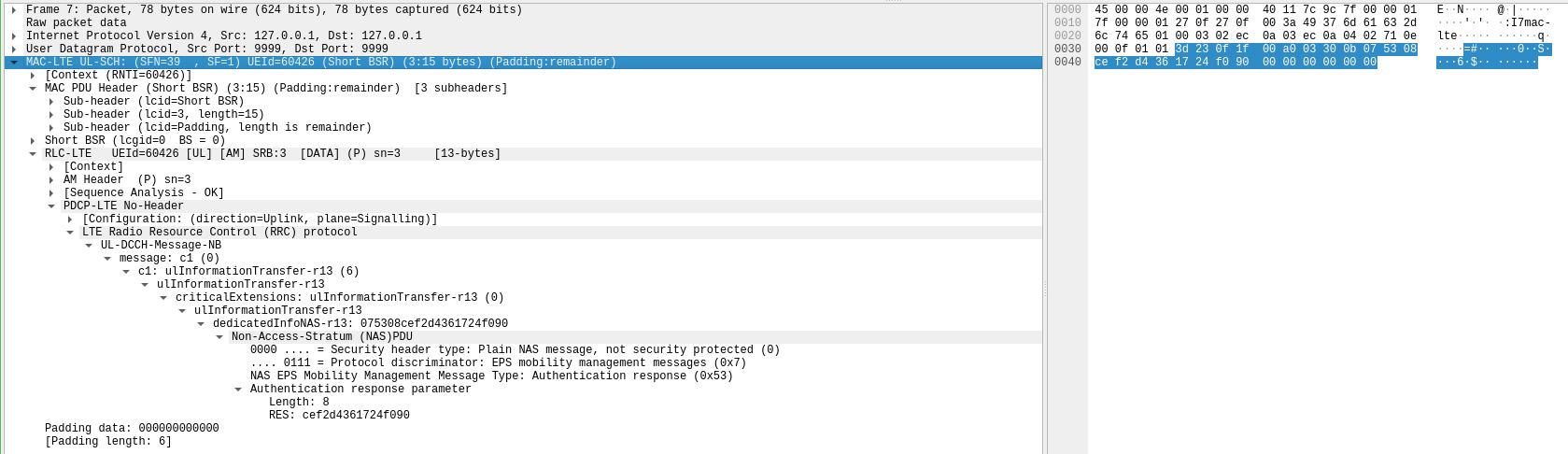
The next message is an authentication response NAS PDU. We infer that the NAS has sent an authentication request message. The authentication response proves that the UE has the SIM with the right key, and that the network also has this key. As part of this authentication process, keys for an EPS security context which allows encryption and integrity of NAS messages are derived.
The next message is also fragmented into two AM PDUs. It is a NAS message that is “integrity protected and ciphered with new EPS security context”. We know (see Table 9.3.1 in TS 24.301) that the only message that can carry this value in the security header type is the security mode complete NAS message. We infer that this message has been sent as a reply to a security mode command NAS message sent by the network. My post using srsRAN as an example for LTE MAC layer analysis shows how this exchange works.
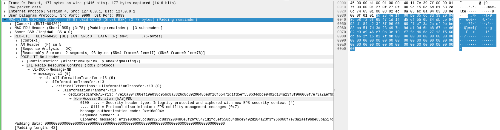
However, we notice that the encrypted security mode complete message here is quite long. The NAS PDU has 91 bytes. In comparison, the security mode complete NAS PDU in the srsRAN example has only 8 bytes. What causes the difference? To guess this we need to look at Table 8.2.21.1 in TS 24.301, which shows the structure of the security mode complete message.
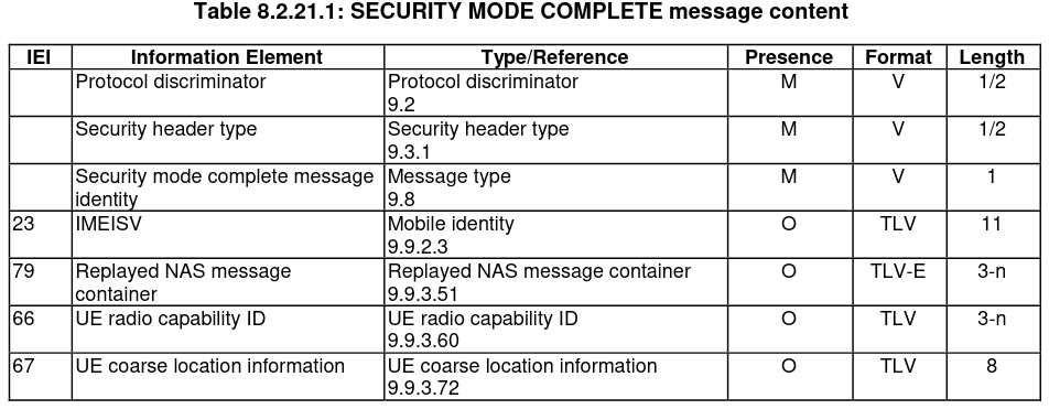
The mandatory fields in the message are short (they account for the last 2 bytes in the 8-byte srsRAN example). However, there are some optional fields. Three of these are sent as replies to optional requests included in the security mode command message: IMEISV request, UE radio capability ID request, and UE coarse location information
request. The replayed NAS message container is described in Section 9.9.3.51 in TS 24.301. This section says that “The purpose of the Replayed NAS message container IE is to, during an ongoing attach or tracking area updating procedure, re-send the ATTACH REQUEST or TRACKING AREA UPDATE REQUEST message with which the UE
had initiated the procedure, if the MME has included a \(\mathrm{HASH}_{\mathrm{MME}}\) in the SECURITY MODE COMMAND message and the \(\mathrm{HASH}_{\mathrm{MME}}\) is different from the hash value locally calculated at the UE as described in 3GPP TS 33.401.”
The attach request NAS PDU in this recording had 69 bytes. So I suspect that this is what is happening here, and that the replayed attach request is responsible for most of the size of the security mode complete message.
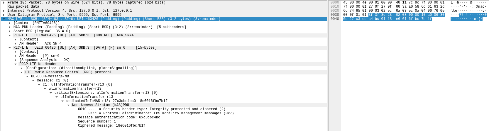
The next message is an encrypted NAS message. The size of the NAS PDU is 13 bytes. By the moment in which it happens and the size, I think that this is an attach complete message. The attach complete in the srsRAN example also has 13 bytes, and it happens at this point, after the UE receives an attach accept message. In that example, the attach accept carries an activate default EPS bearer context request ESM message that activates EPS bearer 5, and the attach complete carries an activate default EPS bearer context accept ESM message that confirms this activation. I guess that the same happens here.
After this message, the UE sends an AM ACK in SRB 3, so we infer that the eNB has sent something in the DL-DCCH-NB, but that message does not have a reply from the UE. At this point, there are no transmissions until 21 seconds later the UE sends another AM ACK in SRB 3. As I mentioned above, I think that this is an ACK to an RRC connection release message in which the UE is told to disconnect because of inactivity.
So far we have seen that 40 seconds after being switched on, the V16 beacon transmits to attach itself to the NB-IoT network, which includes authenticating and establishing an EPS security context that is used to encrypt NAS messages, and establishing an IPv4 PDN connection. There is no indication that any GNSS geolocation data or other beacon-specific metadata has been transmitted at this point.
Roughly 100 seconds after the attach, the V16 beacon sends NPRACH again and performs a conversation to send a control plane service request message. This conversation is pretty much the same as the one I analysed in the previous post, so I will not give all the details here. I will only point out the details that are interesting.
The RRC connection request is similar to the initial one. However, we see that rather than using a random value as the UE identity for contention resolution, now the S-TMSI is used. This is because presumably the UE was assigned an S-TMSI as part of the attach accept message. The S-TMSI remains valid while the beacon is powered on, and we can see that it uses the same S-TMSI in the following RRC connection requests.
This gives an eavesdropper a way to track V16 beacons by listening to the NB-IoT uplink. Assuming that the only UEs that are transmitting are V16 beacons that behave like this one, or that other UEs can be ignored by how they behave, the eavesdropper can use the following facts:
- The beacon transmits the IMSI as part of the attach request
- The first RRC reconnection happens roughly 100 seconds after the attach request, and contains the S-TMSI. Assuming that not many beacons are active, this gives the eavesdropper a way to associate the IMSI and the S-TMSI by this timing
- All future RRC connection requests use the same S-TMSI while the beacon is powered on
- Within an RRC connection, all the NPUSCH transmissions done by the same UE can be tied to the S-TMSI in the RRC connection request because they share the RNTI
Another thing we notice in this RRC connection request is that the establishment cause is now mo-Data instead of mo-Signalling. This makes sense, because the beacon now has user data to transmit.
Note that the beacon timing does not match what the high-level descriptions of V16 beacons say. It is said that a V16 beacon first transmits its position data 100 seconds after power on, and then it retransmits every 100 seconds. However here we see that this beacon attaches to the network 40 seconds after power on, sends its first position data 40 + 100 = 140 seconds after power on, and then it sends the position data again every 100 seconds.
The RRC connection setup complete message is used to send a control plane service request NAS message as in the previous post. There are a couple curious things. First, I have no idea why Wireshark is attempting to dissect the ESM message container contents field, which is encrypted. It doesn’t do so with the PCAP from the previous post or with the control plane service request message that comes 100 seconds later in this PCAP. Because the field is encrypted, Wireshark gets nonsensical values and gives a warning.
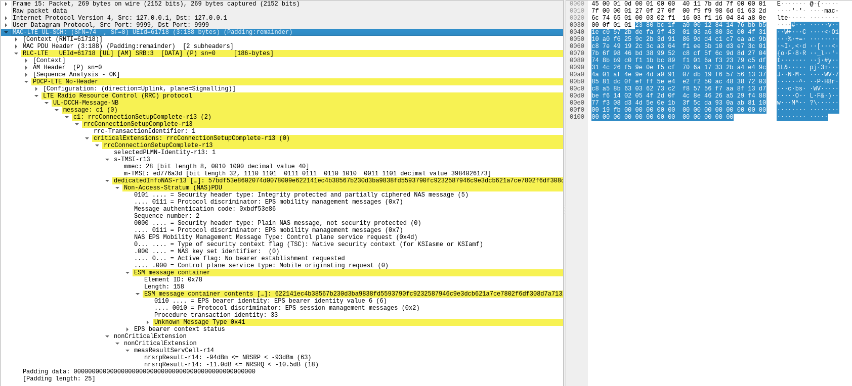
The second remark is that the RRC connection complete message includes NRSRP and NRSRQ measurements as in the first RRC connection complete message. I don’t know why these weren’t present in the previous post. Maybe something is configured differently in the SIB-NB of the two cells, since in the previous post the UE also sent “no measurements” in the cqi-NPDCCH-r14 field of the RRC connection request.
Another thing that is good to note is that the sequence number for this NAS PDU is 2. The encrypted attach complete message was sent with sequence number 1, and the encrypted security mode complete message was sent with sequence number 0. Every time that the beacon now wakes up to send a control plane service request, the sequence number is incremented by one. In the previous post the control plane service request message had a sequence number of 5. This means that this was the 4th time that the beacon transmitted its position data, so it had been powered on for about 440 seconds.
After the control plane service request message is sent, just as in the previous post, we see a partial retransmission because the AM ACK is not received in time. Then the UE sends an AM ACK to acknowledge the reply to the control plane service request, and it does not transmit again until it needs to ACK the RRC connection release.
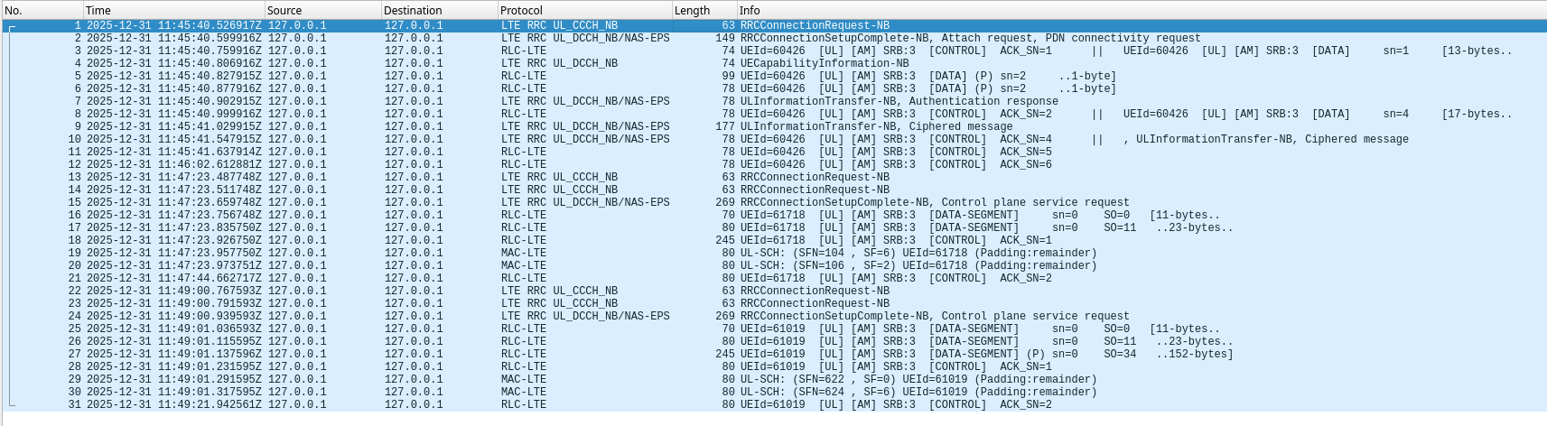
The following Wireshark listing shows a summary of all the MAC PDUs in the recording.
What is inside the control plane service request encrypted data?
Since the ESM message inside the control plane service request NAS message is encrypted, we do not know exactly what it contains. However we can imagine. While doing more research about the V16 beacons, I found a vulnerability report written by Luis Miranda Acebedo a few weeks ago. In this report, Luis indicates that he used physical access to a V16 beacon and took advantage of a debug serial port to obtain logs. The logs contain AT commands exchanged with the beacon NB-IoT modem and packet payload contents. These indicate that the beacon data, which includes GNSS geolocation, IMEI, a timestamp, and other parameters, are sent in plaintext in a UDP message to IP address 172.31.46.149 port 50000.
Luis’ report is based on studying a beacon of the brand Help Flash IoT. This model is different from the one I’m using here, and it uses the Vodafone network instead of the Orange network, so we cannot directly extrapolate Luis’ findings. However, we can imagine that perhaps Orange and Vodafone have set up their V16 beacon network infrastructure similarly.
The control plane CIoT EPS optimization supports sending IP and non-IP user data. The NAS message sent by the UE arrives to the MME, and the MME forwards the user data to its corresponding destination: IP user data is sent to the P-GW for the corresponding PDN through the S-GW; non-IP user data is sent directly to an SCEF (see for instance the diagram in Sharetechnote). Here we have seen that the UE included in the attach request a PDN connectivity request for an IPv4 PDN. I believe that this means that it must be using the control plane CIoT EPS optimization to send IPv4 data to this PDN, rather than non-IP data.
It is quite reasonable to think that the IPv4 user data is a UDP packet, as in the beacon that uses the Vodafone network. Since we have seen that there is only one control plane service request message sent each time, and that presumably a response message is received in the DL-DCCH-NB (we can see the corresponding AM ACK), this rules out more complex protocols with handshaking at the IP level. It is also quite likely that the data in this UDP packet is unencrypted, and that the system relies on the encryption and integrity given by the control plane service request NAS message.
Luis points out in his report that the fact that the UDP packet data is unencrypted and unauthenticated is a security problem. I do not agree. If the PDN where this packet goes is a trusted private PDN, then sending an unencrypted packet is probably fine from a security point of view. The data is encrypted and integrity protected in the control plane service request NAS message by using the EPS security context. This provides a secure tunnel between the UE and the MME that has been established by authenticating both endpoints using the keys in the UE SIM. After the UDP packet reaches the MME, it is then transported only inside a trusted private network. In particular, the data is protected while it crosses the radio network, which is where an attacker could attempt to read or modify the data.
Probably there is still a potential attack vector. If the SIM (or eSIM) in a V16 beacon is moved to an NB-IoT modem connected to a computer, or if the software that runs on the beacon is modified, an attacker could connect to the cellular network in the same way as the regular V16 beacon and use the same procedure to send a UDP packet that contains fake data, such as false geolocation data and/or the IMEI or serial number of another beacon. This would probably inject a fake report successfully into the system. It is possible that the system performs some kind of deep packet inspection that allows it to reject some of this fake data, but I don’t think it is this sophisticated. For instance, it could check that the IMEI and other data identifying the beacon that appears inside the UDP message matches the IMSI that was used to establish the network connection (recall that the IMSI has been validated as part of the UE authentication). However I don’t think that the IMSI is available at the receiver of the UDP packet. The only solution that I see to this attack vector is to ensure that all V16 beacons are completely tamper proof. Otherwise, even if the UDP payload was encrypted and authenticated, it would be possible to modify the beacon software to inject fake data before the encryption and authentication happens. Preventing any kind of tampering is probably too expensive to be feasible. Also keep in mind that if any abuse is detected, the network operator can disable the SIM that is being used, so future authentication attempts using that SIM will be rejected by the network.
Summary
In this post we have decoded a recording of the NB-IoT uplink of a V16 beacon since the moment it is turned on and begins transmitting. We see that 40 seconds after power on, the beacon attaches to the NB-IoT network and obtains PDN connectivity. This involves authenticating against the network and obtaining keys for an EPS security context used to encrypt subsequent NAS messages. The beacon does not send any GNSS geolocation data at this point. After 100 seconds, the beacon reconnects to the RRC and sends a control plane service request message that embeds the GNSS geolocation and other beacon metadata encrypted with the EPS security context. This is done again every 100 seconds. The eNB releases the beacon from the RRC because of inactivity 20 seconds after each of these transmissions. This requires the beacon to send ACKs both at the HARQ level and at the AM level.
Code and data
I have published the recording used in this post in the dataset “Recording of the NB-IoT uplink of a V16 beacon” in Zenodo. The remaining materials are in my LTE repository. This includes the Jupyter notebook used for decoding, the GNU Radio flowgraph used to resample the recording to 1.92 Msps, and the PCAP file containing the decoded MAC PDUs.
One comment