JY1SAT is a Jordanian 1U Amateur cubesat that carries a FUNcube payload by AMSAT-UK. As usual, the FUNcube payload on-board JY1SAT has a linear transponder with uplink in the 435MHz band and downlink in the 145MHz band, and a 1k2 BPSK telemetry transmitter in the 145MHz band. The novelty in comparison to the older FUNcube satellites is that the BPSK transmitter is also used to send SSDV images and Codec2 digital voice data.
Here I show how to decode the SSDV images using gr-satellites.
The IARU R1interim meeting is being held in Vienna, Austria, on April 27 and 28. This post is an overview of the proposals that will be presented during this meeting, from the point of view of the usual topics that I treat in this blog.
The proposals can be found in the conference documents. There are a total of 64 documents for the meeting, so a review of all of them or an in-depth read would be a huge work. I have taken a brief look at all the papers and selected those that I think to be more interesting. For these, I do a brief summary and include my technical opinion about them. Hopefully this will be useful to some readers of this blog, and help them spot what documents could be more interesting to read in detail.
The AO-40 FEC protocol used a concatenated code with a (160, 128) Reed-Solomon code and an r=1/2, k=7 convolutional code, together with scrambling and interleaving to achieve very good performance. The same protocol has then been used in the FUNcube satellites, so I have an AO-40 FEC decoder in gr-satellites since I added support for AO-73.
It is quite easy to notice that the QO-100 beacon transmits both uncoded and FEC messages. Indeed, using my gr-satellites decoder, I see that an uncoded message is transmitted every 23 seconds approximately. Since an uncoded message comprises 514 bytes, it takes 10.28 seconds to transmit it at 400baud, so something else must be sent between uncoded messages.
A FEC message is formed by 5200 symbols (after applying FEC), so it takes 13 seconds to transmit at 400baud. This gives us the total 23.28 seconds that I had observed between uncoded messages. Note that the contents of the uncoded and FEC blocks are different. An uncoded block contains 8 lines of 64 characters plus 2 bytes of CRC. A FEC block only contains 4 lines of 64 characters, and no CRC.
I have added a FEC decoder to the QO-100 decoder in gr-satellites, so that it now decodes both FEC and uncoded messages.
A couple months ago, I added a decoder for Astrocast 0.1 to gr-satellites. I spoke about the rather non-standard FX.25 protocol it used. Since then, Mike Rupprecht DK3WN and I have been in contact with the Astrocast team. They noticed the mistake about using NRZ instead of NRZ-I, and in February 13 they sent a software update to the satellite to use NRZ-I instead of NRZ. However, the satellite has some failsafe mechanisms, so sometimes it is seen transmitting in the older NRZ protocol.
Mike has also spotted Astrocast 0.1 transmitting sometimes in 9k6, instead of the usual 1k2. This is used to download telemetry, and it is only enabled for certain passes. The coding used for this telemetry download is different from the FX.25 beacon. The team has published the following information about it. The coding follows CCSDS, using five interleaved Reed-Solomon encoders. A CCSDS scrambler is also used.
Following this variety of protocols, I have added new decoders for Astrocast 0.1 to gr-satellites. The astrocast.grc decoder does NRZ-I FX.25, and should be used for the beacon. The astrocast_old.grc decoder implements NRZ FX.25, and should be used for the beacon when the satellite is in failsafe mode. The astrocast_9k6.grc decoder serves to decode the 9k6 telemetry downloads. Sample recordings corresponding to these three decoders can be found in satellite-recordings.
On February 14, the Amateur transponders on Es’hail 2 (which now has the AMSAT designation QO-100) were inaugurated. Since then, two beacons are being transmitted by the groundstation in Doha (Qatar) through the narrowband transponder. These beacons mark the edges of the transponder.
The lower beacon is CW, while the upper beacon is a 400baud BPSK beacon that uses the same format as the uncoded beacon of AO-40. I have already talked about the AO-40 uncoded beacon in an older post, including the technical details.
Based on my AO-40 decoder in gr-satellites, I have made a decoder for the QO-100 beacon. Patrick Dohmen DL4PD has been kind enough to write some instructions about how to use the old ao40_uncoded decoder with the BATC WebSDR. I recommend that you use the new qo100 decoder. You just have substitute ao40_uncoded by qo100 in Patrick’s instructions
As additional hints, I can say that for the best decoding, the beacon must be centred at 1.5kHz into the SSB passband. The centre of the signal is easy to spot because there is a null at the centre, due to the use of Manchester encoding. Frequency stability is somewhat important with this decoder, so if your LNB drifts too much you may run into problems.
The SNR of the beacon over the transponder noise floor is rather high, so you should achieve a clean decoding unless you are using a very small station and you have the transponder noise way below your receiver noise floor.
The following data is being currently transmitted on the beacon (the timestamps and packet numbers are added by gr-satellites):
2019-02-19 21:56:27 Packet number 68 K HI de QO-100 (DL50AMSAT BOCHUM UPT: 3d 0h 29m CMD: 91 LEI_REQ: 0 LEI_ACT: 0 TEMP: 56 C VOLTAGES: 1.0 1.8 1.0 1.0 1.8 1.5 1.3 0.0 0.5 Volts TFL: 0 TFE: 0 TFH: 0 HFF: 0 HTH: 0 HR: 0
2019-02-19 21:56:53 Packet number 69 L HI de QO-100 (DL50AMSAT BOCHUM EXPERIMENTAL MODE. Measurements and tests being conducted, experimental transponder use OK, but expect ground station tests Watch this space and www.amsat-dl.org for further announcements
Astrocast 0.1 is an Amateur satellite built by the Lucerne University of Applied Sciences and Arts (Hochschule Luzern). It is an in-orbit demonstrator for a future constellation of small satellites providing L-band data services for internet of things applications. The Amateur payload includes an on-board GPS receiver and a PRBS ranging signal transmitter for precise orbit determination .
This satellite was launched on December 3 on the SSO-A launch, but we only have payed attention to it recently. Its IARU coordinated frequency is 437.175MHz (actually it is a bit strange, because the IARU coordination data speaks about Astrocast 0.2, which hasn’t been launched yet). However, the satellite appears to be transmitting on 437.150MHz.
As it turns out, we had an unidentified object transmitting on 437.150MHz. This object was first thought to be RANGE-A, which was also on the SSO-A launch, as this frequency was assigned to RANGE-A. However, the RANGE-A team confirmed that this wasn’t their satellite, and I wasn’t able to identify the modem used by the mystery 437.150MHz signal.
Yesterday, Mike Rupprecht DK3WN noticed that this unidentified signal corresponded to Astrocast 0.1, and sent me some technical documentation about the protocols used by this satellite. Using that information, I confirmed that the mystery satellite at 437.150MHz was indeed Astrocast 0.1 and now I have added a decoder to gr-satellites.
D-STAR One are a series of Amateur satellites with an on-board D-STAR digital voice repeater. The first satellite of the series, called D-STAR One, was launched on November 2017 but was lost due to a problem with the upper stage of the rocket. The second satellite, called D-STAR One v1.1 Phoenix, was launched in February 2018 but never worked. On 27 December 2018, a Soyuz rocket launched the next two satellites in the series: D-STAR One Sparrow and D-STAR One iSat. I hear that, unfortunately, these two newer satellites haven’t been coordinated by IARU.
Besides using the D-STAR protocol, these two satellites also transmit telemetry in the 70cm Amateur satellite band using the Mobitex protocol, as described in the CMX990 modem datasheet. They use GFSK at 4800 baud.
In the past, I have talked about the Mobitex protocol in the context of the BEESAT satellites by TU Berlin. I described somenotes about the Mobitex-NX variant used in these satellites, and contributed to the beesat-sdr GNU Radio decoder for the Mobitex-NX protocol.
Now, I have adapted the Mobitex-NX decoder to work also with the D-STAR One satellites, and added a decoder to gr-satellites. The decoder requires my fork of beesat-sdr to be installed.
Even though the cubesat LilacSat-1 was launched more than a year ago, I haven’t played with it much, since I’ve been busy with many other things. I tested it briefly after it was launched, using its Codec2 downlink, but I hadn’t done anything else since then.
LilacSat-1 has an FM/Codec2 transponder (uplink is analog FM in the 2m band and downlink is Codec2 digital voice in the 70cm band) and a camera that can be remotely commanded to take and downlink JPEG images (see the instructions here). Thus, it offers very interesting possibilities.
Since I have some free time this weekend, I had planned on playing again with LilacSat-1 by using the Codec2 transponder. Wei Mingchuan BG2BHCpersuaded me to try the camera as well, so I teamed up with Mike Rupprecht DK3WN to try the camera this morning. Mike would command the camera, since he has a fixed station with more power, and we would collaborate to receive the image. This is important because a single bit error or lost chunk in a JPEG file ruins the image from the point where it happens, and LilacSat-1 doesn’t have much protection against these problems. By joining the data received by multiple stations, the chances of receiving the complete image correctly are higher.
The SiriusSats are using 4k8 FSK AX.25 packet radio at 435.570MHz and 435.670MHz respectively, using callsigns RS13S and RS14S. The Tanushas transmit at 437.050MHz. Tanusha-3 normally transmits 1k2 AFSK AX.25 packet radio using the callsign RS8S, but Mike Rupprecht sent me the other day a recording of a transmission from Tanusha-3 that he could not decode.
It turns out that the packet in this recording uses a very peculiar modulation. The modulation is FM, but the data is carried in audio frequency phase modulation with a deviation of approximately 1 radian. The baudrate is 1200baud and the frequency for the phase modulation carrier is 2400Hz. The coding is AX.25 packet radio.
Why this peculiar mode is used in addition to the standard 1k2 packet radio is a mystery. Mike believes that the satellite is somehow faulty, since the pre-recorded audio messages that it transmits are also garbled (see this recording). If this is the case, it would be very interesting to know which particular failure can turn an AFSK transmitter into a phase modulation transmitter.
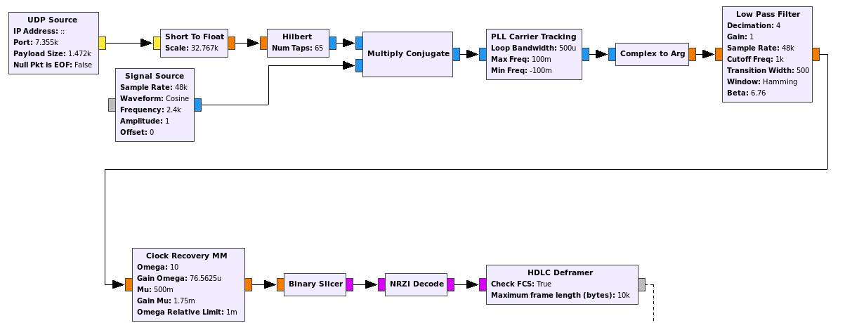
I have added support to gr-satellites for decoding the Tanusha-3 phase modulation telemetry. To decode the standard 1k2 AFSK telemetry direwolf can be used. The decoder flowgraph can be seen in the figure below.
TANUSHA-3 gr-satellites decoder
The FM demodulated signal comes in from the UDP source. It is first converted down to baseband and then a PLL is used to recover the carrier. The Complex to Arg block recovers the phase, yielding an NRZ signal. This signal is lowpass filtered, and then clock recovery, bit slicing and AX.25 deframing is done. Note that it is also possible to decode this kind of signal differentially, without doing carrier recovery, since the NRZI encoding used by AX.25 is differential. However, the carrier recovery works really well, because there is a lot of residual carrier and this is an audio frequency carrier, so it should be very stable in frequency.
The recording that Mike sent me is in tanusha3_pm.wav. It contains a single AX.25 packet that when analyzed in direwolf yields the following.
RS8S>ALL:This is SWSU satellite TANUSHA-3 from Russia, Kursk<0x0d>
------
U frame UI: p/f=0, No layer 3 protocol implemented., length = 68
 dest    ALL     0 c/r=1 res=3 last=0
 source  RS8S    0 c/r=0 res=3 last=1
  000:  82 98 98 40 40 40 e0 a4 a6 70 a6 40 40 61 03 f0  ...@@@...p.@@a..
  010:  54 68 69 73 20 69 73 20 53 57 53 55 20 73 61 74  This is SWSU sat
  020:  65 6c 6c 69 74 65 20 54 41 4e 55 53 48 41 2d 33  ellite TANUSHA-3
  030:  20 66 72 6f 6d 20 52 75 73 73 69 61 2c 20 4b 75   from Russia, Ku
  040:  72 73 6b 0d                                      rsk.
------
The contents of the packet are a message in ASCII. The message is of the same kind as those transmitted in AFSK.
In my previous post I looked at the first SSDV transmission made by DSLWP-B from lunar orbit. There I used the recording made at the Dwingeloo radiotelescope and showed how to decode the SSDV frames and produce a JPEG image.
Only four SSDV frames where transmitted by DSLWP-B, and out of those four, only two could be decoded correctly. I wondered why the decoding of the other two frames failed, since the SNR of the signal as recorded at Dwingeloo was very good, yielding essentially no bit errors (even before FEC decoding).
Now I have looked at the signal more in detail and have found the cause of the corrupted SSDV frames. I have demodulated the signal in Python and have looked at the position where an ASM (attached sync marker) is transmitted. As explained in this post, the ASM marks the beginning of each Turbo codeword. The Turbo codewords are 3576 symbols long and contain a single SSDV frame.
A total of four ASMs are found in the GMSK transmission that contains the SSDV frames, which matches the four SSDV transmitted. However, the distance between some of the ASMs doesn’t agree with the expected length of the Turbo codeword. Two of the Turbo codewords where cut short and not transmitted completely. This explains why the decoding of the corresponding SSDV frames fails.
This is rather interesting, as it seems that DSLWP-B had some problem when transmitting the SSDV frames. I have no idea about the cause of the problem, however. It would be convenient to monitor carefully future SSDV transmissions to see if any similar problem happens again.