One thing I left open in my post yesterday was the convolutional encoder used for FEC in the DSCS-III X-band beacon data. I haven’t seen that the details of the convolutional encoder are described in Coppola’s Master’s thesis, but in a situation such as this one, it is quite easy to use some linear algebra to find the convolutional encoder specification. Here I explain how it is done.
Category: Maths
Mathematics
Earth rotation corrections for range and range-rate in GNSS
In GNSS, when considering the propagation of signals from the satellites to a receiver, it is easier to work in an ECI reference frame, since (ignoring the gravitational potential of Earth), light travels in straight lines in ECI coordinates. However, it is often common to do all the calculations in an ECEF frame, as the final goal is to obtain the receiver’s position in ECEF coordinates, and the ephemerides also use ECEF coordinates to describe the satellite positions. Therefore, a non-relativistic correction needs to be applied to account for the fact that light no longer travels in straight lines when one considers ECEF coordinates. Often, the correction is done as some kind of approximation. These types of corrections are known in the GNSS literature as the Sagnac effect.
The goal of this post is to discuss where the corrections arise from, the typical approximations that can be made, and how these corrections affects the calculation of range and range-rate. I didn’t find a good source in the literature where this is described in detail and in a self-contained way, so I decided to write it myself.
Simulating the TED gain for a polyphase matched filter
Trying to improve the performance of the demodulators in gr-satellites, I am switching to the Symbol Sync GNU Radio block, which was introduced by Andy Walls in GRCon17. This block covers the functionality of all the other clock synchronization blocks, such as Polyphase Clock Sync and Clock Recovery MM, while fixing many bugs.
One of the new features of the Symbol Sync block is the ability to specify the gain of the timing error detector (TED) used in the clock recovery feedback loop. All the other blocks assumed unity gain, which simply causes the loop filter taps to be wrong. However, the TED gain needs to be calculated beforehand either by analysis or simulation, as it depends on the choice of TED, samples per symbol, pulse shaping, SNR and other.
While Andy shows how to use the Symbol Sync block as a direct replacement for the Polyphase Clock Sync block in his slides, he leaves the TED gain as one, since that is what the Polyphase Clock Sync block uses. In replacing the Polyphase Clock Sync block by Symbol Sync in gr-satellites, I wanted to use the correct TED gain, but I didn’t found anyone having computed it before. This post shows my approach at simulating the TED gain for polyphase matched filter with maximum likelyhood detector.
Measuring the gain of a dish
Here I want to show a technique for measuring the gain of a dish that I first learned from an article by Christian Monstein about the Moon’s temperature at a wavelength of 2.77cm. The technique only uses power measurements from an observation of a radio source, at different angles from the boresight. Ideally, the radio source should be strong and point-like. It is also important that the angles at which the power measurements are made are known with good accuracy. This can be achieved either with a good rotator or by letting an astronomical object drift by on a dish that is left stationary.
Projection of a sphere onto the unit sphere in spherical coordinates
The title of this post is quite a mouthful (I couldn’t come up with anything better), so let me start by describing the particular problem that got me thinking into this sort of things.
DSLWP-B Moonbounce
If you have been following my latest posts, you will know that a series of observations with the DSLWP-B Inory eye camera have been scheduled over the last few days to try to take and download images of the Moon and Earth (see my last post). In a future post I will do a chronicle of these observations.
On October 6 an image of the Moon was taken to calibrate the exposure of the camera. This image was downlinked on the UTC morning of October 7. The download was commanded by Reinhard Kuehn DK5LA and received by the Dwingeloo radiotelescope.
Cees Bassa observed that in the waterfalls of the recordings made in Dwingeloo a weak Doppler-shifted signal of the DSLWP-B GMSK signal could be seen. This signal was a reflection off the Moon.
As far as I know, this is the first reported case of satellite-Moon-Earth (or SME) propagation, at least in Amateur radio. Here I do a Doppler analysis confirming that the signal is indeed reflected on the Moon surface and do some general remarks about the possibility of receiving the SME signal from DSLWP-B. Further analysis will be done in future posts.
Lunar orbit perturbations and DSLWP-B
Ever since simulating DSLWP-B’s long term orbit with GMAT, I wanted to understand the cause of the periodic perturbations that occur in some Keplerian elements such as the eccentricity. As a reminder from that post, the eccentricity of DSLWP-B’s orbit shows two periodic perturbations (see the figure below). One of them has a period of half a sidereal lunar month, so it should be possible to explain this effect from the rotation of the Moon around the Earth. The other has a period on the order of 8 or 9 months, so explaining this could be more difficult.
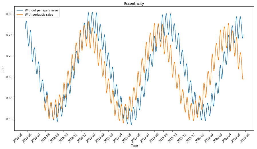
In this post I look at how to model the perturbations of the orbit of a satellite in lunar orbit, explaining the behaviour of the long term orbit of DSLWP-B.
Using a Golay(24,12) decoder for Golay(23,12)
Yesterday I explained an algebraic decoding algorithm for Golay(24,12) and commented that it was not easy to adapt it to decode Golay(23,12). Today I’ve thought of a simple way to use any Golay(24,12) decoder to decode Golay(23,12).
Recall that a systematic Golay(23,12) code is obtained from a systematic Golay(24,12) by omitting the last component of each codeword (i.e., the codeword \((c_1,\ldots,c_{24})\) from the Golay(24,12) code gives the codeword \((c_1,\ldots,c_{23})\) from the Golay(23,12) code). Conversely, one can obtain a systematic Golay(24,12) code from a systematic Golay(23,12) code by adding a parity bit at the end. This means that \(c_{24} = \sum_{j=1}^{23} c_j\), since \(\sum_{j=1}^{24} c_j = 0\) for all words in a Golay(24,12) code.
The idea to decode a Golay(23,12) code with a Golay(24,12) decoder is first to restore the parity bit \(c_{24}\) and then apply the Golay(24,12) decoder. However, if there are errors in the received codeword, the restored parity bit can also be in error, increasing the number of errors in one.
The key remark is that both Golay(23,12) and Golay(24,12) are able to correct up to 3 errors. Therefore, we only care about restoring the parity bit correctly in the case when there are exactly 3 errors. If there are 2 or less errors, adding another error still gives a word decodable by the Golay(24,12) decoder.
Now note that if there are exactly 3 errors in \((c_1,\ldots,c_{23})\), then \(\sum_{j=1}^{23} c_j\) gives the opposite from the parity of the original codeword. Therefore, we should restore \(c_{24}\) as\[c_{24} = 1 + \sum_{j=1}^{23} c_j\]and then apply the Golay(24,12) decoder.
Algebraic decoding of Golay(24,12)
A couple years ago, I implemented a Golay(24,12) decoder to be used in the GOMX-1 decoder in gr-satellites. The implementation can be seen here. I followed the algorithm in the book The Art of Error Correction Coding, Section 2.2.3, without taking much care to understand why the algorithm worked. Now I am doing some experiments with Golay(24,12) and Golay(23,12) codes, so I have needed to revisit that algorithm and understand it well to adapt it to my needs. Here I explain how this algebraic decoder works.
BCH decoder for S-NET
In my previous post, I talked about the coding used by the S-NET cubesats and the implementation of my decoder included in gr-satellites. The decoder was still missing a BCH decoder. I have now implemented a BCH decoder and included it in gr-satellites. Here I describe the details of this decoder.