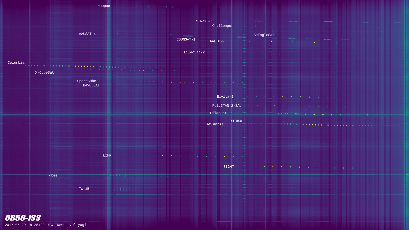
In the previous post, I analysed a QB50 recording. Now I have prepared some waterfalls from my recording using the procedure I already described a while ago. The image above is obtained from a 1600×1024 waterfall with a resolution of 2.93kHz or 0.86s per pixel. I have labelled all the satellites and cropped it to a 1600×900 image that now I’m using as my desktop wallpaper.
I have also made a large 14120×16384 image with a resolution of 183.1Hz or 0.1s per pixel. The image can be downloaded here (142MB). I have found the following interesting crops within the large image. Remember that you can click on each image to view it in full size.
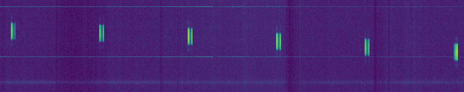
The fast fading that I detected in nSIGHT is clearly visible below. Note that the beacon period is almost, but not quite, an integer multiple of the fading period.
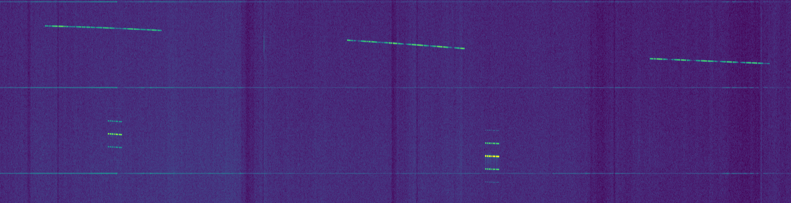
In the image below, we can see that SpaceCube is not very stable in frequency. The carrier frequency tends to rise rapidly each time that the transmitter goes on. Also, the overall trend is a frequency increase, counteracting the frequency decreasing effect of Doppler. This excerpt is near the end of SpaceCube’s pass, so the change in Doppler is not so large. The other French satellite, X-CubeSat, also shows a similar behaviour.

AAUSAT-4 usually transmits in 4k8 FSK using CCSDS FEC, but it also transmits a CW beacon sometimes. Both can be seen below.

Finally, a couple of CW satellites with interesting behaviour. On the upper part of the image below we can see BeEagleSat with fading. On the lower part, we can see Aalto-2 with its characteristic sidebands.
Hola Daniel,
First of all congratulations for the blog.
A few days ago, I recorded with gqrx some signals which I believe that were transmitted by QB50 CA03. So, I decided to use your app ca03.grc for gnuradio compagnion and your gr-satellites blocks to decode the beacon.
However, when I open the app ca03.grc in gnuradio-compagnion there is one block missing. The key of the block is sync_to_pdu_packed_0 and I believe that corresponds to the block “sync and create packet PDU” which appears in some of the images of your blog. Could you help me to understand why this block does not appear in gnuradio-compagnion?
I have installed gnuradio and your gr-satellites using PyBombs.
Thanks in advance.
Hi Fernando,
“Sync and create packed PDU” is a hierarchical block. You need to generate and install the hierarchical blocks in gr-satellites. See the gr-satellites README (essentially, there is a shell script that does the job for you).
Hello Daniel,
Indeed. Thank you! Now the block appears!
On the other hand, I would like to kindly ask you about the demodulation process since I do not understand the input signal and the first demodulation steps.
– Which type of signal do you have at the input port of the Low Pass filter? Is it a real signal with the carrier shifted to 0 Hz? At which sample rate? I guess that in my case I will have to do modifications since I have the I/Q signal at baseband.
– Why does the filter have only 2.4 kHz bandwidth when the signal has about 4.8 kHz bandwidth?
In general terms, I am bit lost in the steps of the Low pass filter and the Clock Recovery since I cannot identify the GFSK demodulation process in those two blocks. Please, could you explain me a bit how it works or indicate me where I could find an explanation?
Thanks in advance.
At the input of the low pass filter the signal is already FM-demodulated, so we expect to find an NRZ 4800baud signal. In your case you need to FM-demodulate the signal, for instance by using quadrature demod.
The bandwidth of the filter is 2.4kHz because an 4800baud NRZ signal fits into this bandwidth.
There is no GFSK demodulation at all, since FM demodulation has already been done outside the flowgraph. In the flowgraph, only clock recovery and bit slicing is done.
Hi Daniel,
Thank you for the clarification! I will work in the demodulation and I will try your app afterwards. Thank you!
Fernando
Hi Daniel again,
I have been analyzing some recordings that I did of Ex-Alta1 cubesat and I have concluded that I am not able to decode the beacon because I have a very bad SNR.
If you do not mind, I would like to ask you for some recommendation of a suitable hardware setup for the detection of cubesats (antenna, receivers…) with a good SNR. I believe that mine is not good enough (I have a yagi with a 20dB preamp on the roof, 100 m cable 🙁 and a hackrf one).
Thanks in advance.
Hi Fernando,
The equipment I used in this QB50 recording was very basic: a handheld 7 element hand-pointed yagi (the Arrow satellite yagi) and a short coax (1.5m) straight into the LimeSDR. This only works if the LimeSDR doesn’t pick up interference from out-of-band signals. Usually, filtering in front of it would be required. In most of my other satellite recordings I use the FUNcube dongle instead of the LimeSDR, because it has SAW filters for the 2m and 70cm bands.
Your equipment is much better than mine, so unless there is a huge problem, it should outperform mine. Also, Ex-Alta1 was pretty strong in my recording, so you should definitely start to look for the problem in your system. You don’t say which yagi you use, but even a small yagi such as mine is sufficient for the reception of many low Earth orbit satellites. I assume you have a linearly polarized yagi. The drawback of this is that sometimes polarization will not match and you’ll get deep fading. Still, polarization should be OK half of the time. An advantage of a hand-held yagi is that you can always adjust and match your polarization. A circularly-polarised yagi is better. A dual-polarization receive system is even better, but none of these are essential. I assume you have azimuth and elevation pointing. Without this, a yagi is pretty much useless. Check that your rotator is working as it should.
Next, your preamp should have a low noise figure, but almost any preamp these days has. It’s more important that it doesn’t saturate or suffer interference from other out-of-band or in-band signals. Depending on your local RF environment you may need filtering to protect your preamp. 100m of cable sounds like a very long run. Is this number correct? If you need such a long run of coax, you should use low-loss coax, as low-loss as you can get. The losses at 430MHz of a 100m run of coax can be pretty high. Calculate the losses of your coax run, using the data from the manufacturer, and if you can, measure the losses to see if it matches the calculated value. Then you must take into account the losses when evaluating if your preamp is fine. Your preamp should compensate for the coax loss, while still providing enough gain to dominate the noise figure of the system (this might help).
Finally, the HackRF is not a superb receiver, but the noise figure should be dominated by the preamp, so no problems with that. The HackRF has no filtering, so watch out from out-of-band interference, especially if your preamp has no or little filtering. It is important to set the gain appropriately. If you have another receiver at hand, try to substitute it to see if your problem is with the HackRF.
Hi Daniel,
Thank you for your super-quick answer.
Regarding the antenna, I had the chance to install a big 3.4 m cross yagi antenna (WX7036) from Wimo configured in right handed circular polarization. As you have already guessed, it is mounted in a el-az automatic rotor .
The preamp is a standard 20 dB LNA. I cannot currently reduce the distance of the coax cable because the antenna is installed far from the receiver. However, it is a good quality cable and should theoretically introduce only about 10 dB losses.
From your answer, I am also concluding that I have a problem in my setup. I will have to review it carefully in order to find problems.
For the case of the Ex-Alta1, I could get the peak of the signal about 5 dB above the noise in gqrx spectrum display. Please, could you tell me how much the Ex-Alta-1 signal is above the noise floor in your setup? That will give me a reference on how much I should improve my system.
Also, please could you tell me where I could buy an antenna like yours? I am thinking that maybe I could try to reproduce your setup in order to understand better where the problem could be.
Thanks in advance!
10dB loss in the coax is a lot. Perhaps you’ll need more gain in your preamp to compensate for this. Check that the preamp dominates the noise figure of your system. When you turn the preamp on, you should see at least a 10dB increase in the noise floor in your receiver.
I’m not sure about the SNR of Ex-Alta1 in my recording, as I’ve never measured. Judging from the waterfall images, it is at least 20dB for the strongest packets. The dynamic range of the waterfalls in this post is 30dB. The colormap used is viridis. With this information, you can estimate the SNR from the waterfall. Otherwise, the WAV IQ recording is available here (16GB), so you can measure it yourself.
The Arrow antenna is sold here in the US. If you’re in Europe, you can buy it directly or from some store that imports it, such as AMSAT-UK.
Daniel,
Thanks for your recommendations. I have a short coax cable which I will try to use to connect directly the receiver to the antenna. Let’s see if it works better.
I am in Madrid, so I will try to get a small antenna in a European store. I will check AMSAT-UK.
Thanks!
Hi Fernando,
I’m also near Madrid. People here complain about interference in the 70cm band from frequency inhibitors run by the government in several places of Madrid. Are you sure they are not the cause of the problem with your station?
Hi Daniel,
The problem should not be an inhibitor since I can see signals in the spectrum (although there are some interferences). Currently, I am only using gqrx to analyze the spectrum, and my first goal is to get a decent carrier signal above the noise floor.
Apart of checking the preamp, cables… I am thinking that maybe I should get a more sensitive receiver wrt Hackrf… Do you have any opinion about SDRplay? It looks like that it can be obtained in Europe without too much hassle.
By the way, do you have any recommendation about where to buy an Arrow antenna (or similar amateur antenna) in Madrid? Usually, I am getting the parts from Germany. Or do you recommend that I get it from UK?
Thanks in advance and sorry for bothering you with so many questions!
I don’t like the SDRplay, as everything about it is closed source. I don’t know much technical information about it (not a lot is available, actually). The datasheet of the MSi2500 RFIC says very little. The MSi001 tuner is also used in the FUNcube Dongle Pro+, which works very well. More info here. Leif Asbrink has some technical videos about the SDRPlay in his Youtube channel.
Don’t get a better receiver just because it is more sensitive. The noise figure of your system should be dominated by your preamp and the sensitivity of your SDR should matter little. It is very important to understand system noise figures, noise temperatures and so on. Get a better receiver because of dynamic range, IMD performance, frequency coverage, bandwidth and so on.
The only shop in Europe I know that sells the Arrow is the Amsat UK shop. There might be others. You have to run the numbers carefully to see if it is cheaper buying from Amsat UK or from Arrow in the US. Probably it depends on the GBP to EUR exchange rate.
Thanks for your advice!
Indeed, I was considering to change the Hackrf for something with a better dynamic range, less intermodulation distorsions… I was also considering to get Airspy, but I think that is harder to get it in Europe. It looks like that Sdrplay and Airspy have similar performances in terms of dynamic range, noise figure and intermodulation distorsions.
But as you say, first I will start reviewing the calculations of the link budget and system noise of my station in order to better understand where the limitations are.
Thanks!