Today I’ve finished my prototype of the Arduino LED driver. I had already soldered and tested all the components quite a while ago, but I ran out of connectors for the LED strings, so I had to wait for more to arrive from China.
This project uses an Arduino-compatible ATmega328P and is able to drive up to 18 regular LED strings using the BCR420UW6 linear driver and 4 high-power LED strings using the AL8808 switching driver. The intended application is programmable lightning, such as Christmas or party lights.
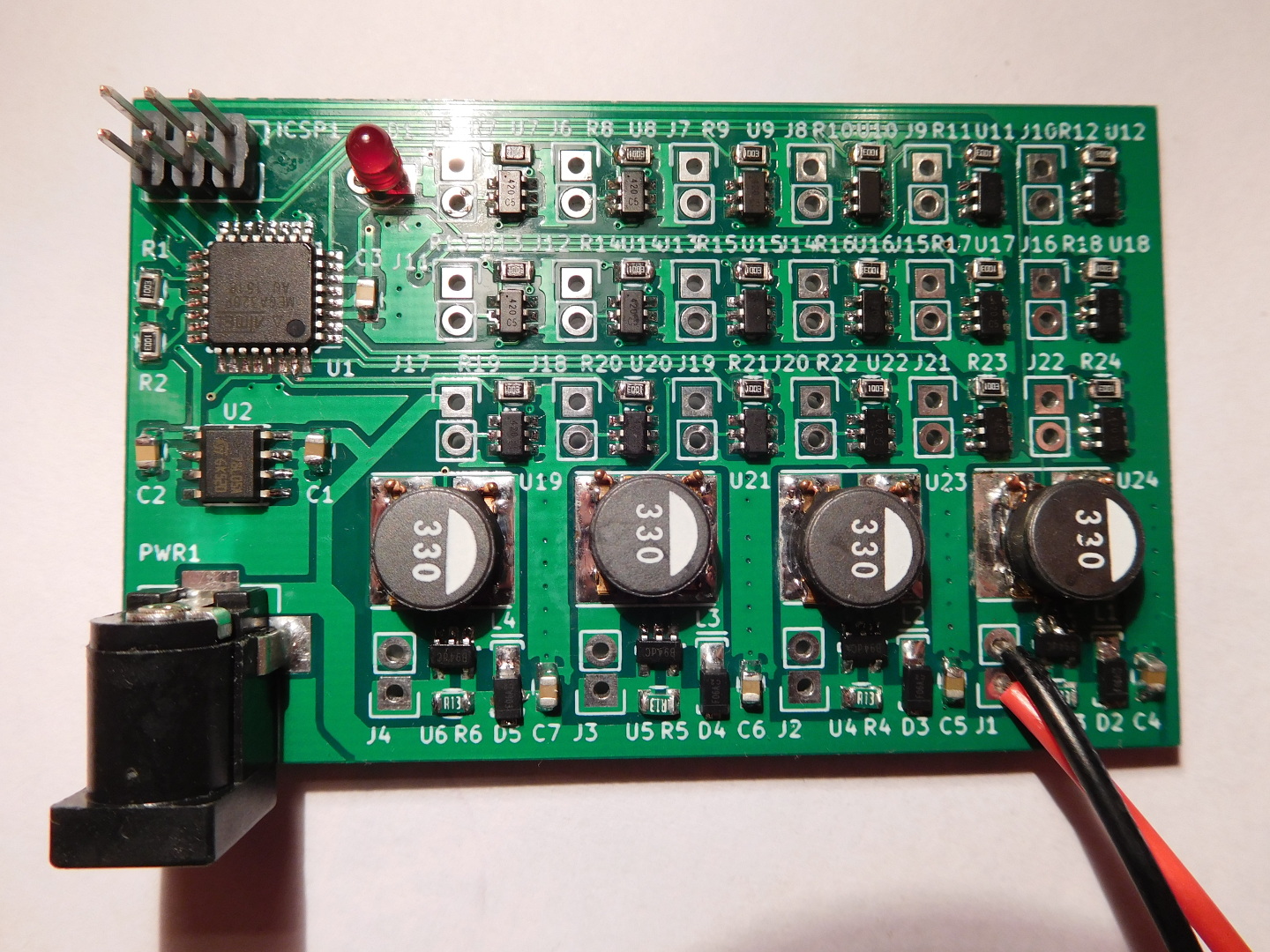
The project is designed to run from an external 12V supply. However, it supports up to 30V if properly rated capacitors are installed, so feeding 24V or so may be a better idea if one intends to use longer LED strings. The ATmega328P is run from a L78L05ACD 5V 0.1A linear regulator. No external crystal or resonator is included, so the 328P is supposed to run using its internal oscillator. The only external communication included is an ISP port to program the microcontroller. This may be used to interface to other devices over SPI. However, one loses the ability to run 3 of the linear LED drivers, since all of the 328P I/O pins are used in this project.
A 100Ω external resistor is used with the BCR420UW6 for a typical LED current of 20mA. A resistor of a different value can be used for a LED current of up to 350mA, but for high currents there can be thermal issues (it’s clearly impossible to run all the 18 drivers at 350mA). The AL8808 uses a current shunt of 130mΩ, which gives a nominal current of 770mA. A 33uH inductor and a DFLS240L diode are used with this switching regulator.
All resistors and capacitors are 0805, which is quite easy to solder by hand. The ATmega328P is a TQFP-32, which can be soldered by hand using the technique of drag-soldering. The AL8808 is a SOT-25. The two pins in one side can be soldered individually and the other three pins can be drag-soldered. The BCR420UW6 is a SOT-26. Both sides of this chip can be drag-soldered. The 5V regulator is a SOIC-8, so its pins can be soldered individually. Perhaps a smaller footprint for the regulator would have been nicer. The 3mm LED is just a power indicator that runs from the 5V rail.
The project doesn’t specify connectors for the LED strings, so different types of connectors may be used or the LED string can be soldered directly for the PCB. The footprint in the PCB is for a standard 2×1 0.1” pitch header. I’m using JST RCY connectors in this prototype, as that’s what I already have in my LED strings.
I made two mistakes while building this prototype. The first was that the footprint for the DFLS240L was included backwards in the PCB, due to a pin numbering issue. I have a batch of 10 PCBs with this problem, but it is something minor, because the diode can be soldered in the correct orientation without much effort (but one has to pay some attention). The other mistake was specifying and soldering 100kΩ external resistors instead of 100Ω for the BCR420UW6’s (a keen eye will spot that mistake on the picture above). I only noticed that while writing this post, but replacing them has being easy.
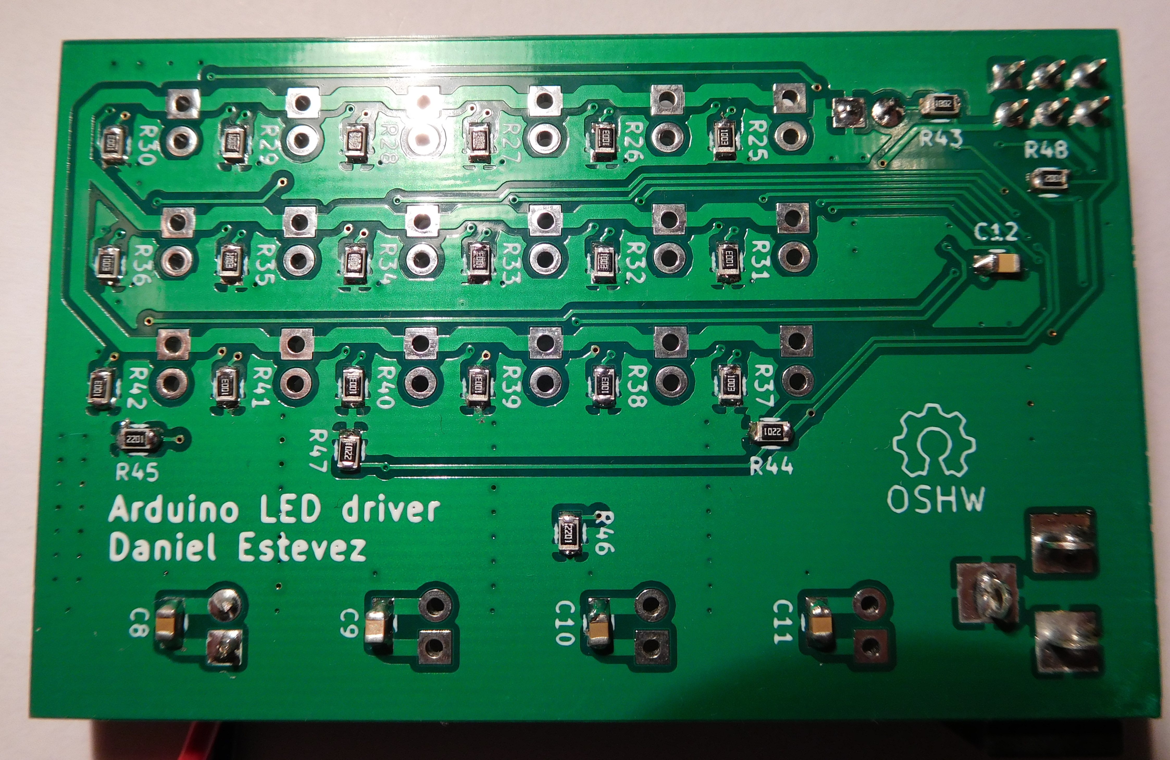
This project is Open Source Hardware. I’ve uploaded the Kicad project files to GitHub. I have spare parts that can be used to build this project, so I’m offering them as a kit.